manuals.online logo
Brands
  1. Home
  2. •
  3. Brands
  4. •
  5. KD
  6. •
  7. Mobility Aid
  8. •
  9. KD PL 001 - B User manual

KD PL 001 - B User manual

This manual suits for next models

1

Popular Mobility Aid manuals by other brands

Drive DeVilbiss GoLite 200 operating instructions

Drive DeVilbiss

Drive DeVilbiss GoLite 200 operating instructions

Invacare 8153-J user manual

Invacare

Invacare 8153-J user manual

Clearwell Mobility Brandon User instructions

Clearwell Mobility

Clearwell Mobility Brandon User instructions

Handicare 1100 user manual

Handicare

Handicare 1100 user manual

NRS Healthcare M11090 User instructions

NRS Healthcare

NRS Healthcare M11090 User instructions

Alber Scalamobil iQ operating instructions

Alber

Alber Scalamobil iQ operating instructions

Ferno CCT-PX user manual

Ferno

Ferno CCT-PX user manual

Medline MDS86835DSHEC User Instructions & Warranty

Medline

Medline MDS86835DSHEC User Instructions & Warranty

Guldmann Twin Turner II user manual

Guldmann

Guldmann Twin Turner II user manual

Ferno 35-ITA user manual

Ferno

Ferno 35-ITA user manual

Drive ROOMBA Operation manual

Drive

Drive ROOMBA Operation manual

Gate Balder operating instructions

Gate

Gate Balder operating instructions

Decon wheel TNS Notos Assembly instructions

Decon wheel

Decon wheel TNS Notos Assembly instructions

ExoAtlet ExoAtlet-II user manual

ExoAtlet

ExoAtlet ExoAtlet-II user manual

Invacare Storm Series parts catalog

Invacare

Invacare Storm Series parts catalog

Rhythm Healthcare B3800F manual

Rhythm Healthcare

Rhythm Healthcare B3800F manual

AMF-BRUNS PROTEKTOR installation manual

AMF-BRUNS

AMF-BRUNS PROTEKTOR installation manual

Drive DeVilbiss Healthcare OTTER Instructions for use

Drive DeVilbiss Healthcare

Drive DeVilbiss Healthcare OTTER Instructions for use

manuals.online logo
manuals.online logoBrands
  • About & Mission
  • Contact us
  • Privacy Policy
  • Terms and Conditions

Copyright 2025 Manuals.Online. All Rights Reserved.

Enrich Your Life!
Maintenance Manual
Model: PL 001 – B
Contents
1
I. General Features .…………………………………………………………………….....2
II. Circuit Diagram……………………………………………………………………...….5
III. Operations………………………………………………………………………...….….6
IV. Troubleshooting and Solutions………………………………………………………......7
V. Maintenance Guide………………………………………………………………………9
Ⅰ.General Features
2
①Upper Backrest ②Back Cushion ③Backrest Folding Button ④Armrest
⑤Control Panel ⑥Lithium Battery ⑦Positioning Waist Belt ⑧Seat Base
⑨Leg Guard ⑩Frame ○
11 Splash Guard ○
12 Motor Wheel
○
13 Footrest ○
14 Front Wheel ○
15 Storage Basket ○
16 Legrest
①②
③
④
⑤
⑥
○
14
○
15
○
13
⑩
⑨
⑧
⑦
③
○
11
○
12 ○
16
Ⅰ.General Features
3
○
17 Folding Release Lever ○
18 Anti-Tipping Wheels
○
19 Electromagnetic Brake Levers ○
20 Control Panel Connector
○
21 Control Panel Cable Clip ○
22 Serial Number
○
18
○
21
○
20
○
19
○
17
○
22
Ⅰ.General Features
4
Joystick Control Panel
Number: Function: Description:
1 Power-On Button
Pressing this button will power on the
chair.
2 Power-Off Button
Pressing this button will power off the
chair.
3 Speed Button
Increase the speed of the chair,
Max. speed: 6 km/hr (3.75 m/hr)
4 Speed Button Decrease the speed of the chair.
5 Horn Press horn to sound.
6 Battery Life Indicator Indicate the battery level.
7 Control Joystick
Control the direction and speed of the
chair. Push the joystick towards the
desired direction.
8 Speed Indicator
With 5 LED lights on, the chair at its
max speed. With 1 LED light on, the
chair at its lowest speed.
Off On
⑤
①
③
④
⑧⑥
②
⑦
Ⅱ.Circuit Diagram
5
Faulty wiring diagnosis: 4 and 5 – pin connector
1: Positive
2: Program
3: Communication
5: Negative
+: Positive
-: Negative
S1: Program
S2: Communication
A: Phase A B: Phase B C: Phase C
1: Brake 2: Brake 3: Hall +3
4: Hall 4 5: Hall 5 6: Hall 6
7: Hall – 7
1: Positive
2: Program (S2)
3: Communication (S1)
5: Ne
g
ative
Ⅲ.Operations
6
PL001 comes with two Lithium batteries as the chairs power source. PL001 operates with the
control module delivering all programmed commands to the brushless motors. The joystick
control panel carries out directional commands as well as controlling the speed and power of
PL001. The charging port for PL001 is located on the Joystick Control Panel.
Control Module
Brushless Motors
Lithium battery
charger
Joystick Control
Panel
2-Way splitter control
module cable
Lithium battery
Ⅳ.Troubleshooting and Solutions
7
Power Supply Failure and Battery Failure
Problem Solution
Lithium battery over-current
protection cutting power
supply off
Connect the battery charger to the joystick control panel to re-
activate lithium battery
Poor battery connection Pull out the batteries and re-insert the batteries until a click
sound is heard
Faulty 5-pin connector
Use and set the multimeter to DC voltmeter mode, to measure
the voltage of the 5 – pin connector. If the voltage reading is
below the range of 23 volts, replace the 5-pin connector
Joystick Control Panel:
Faulty 4-pin cable
Use and set a multimeter to Ωresistance mode and follow the
circuit diagram. If open circuit or short circuit is found, replace
the faulty 4-pin cable
Battery casing deformed and
reduced battery life
Deformed casing of the Lithium battery is sign of the battery
reaching the end of its service life. Failing to charge the battery
regularly when the power is low will significantly reduce the
battery life. Please replace batteries immediately
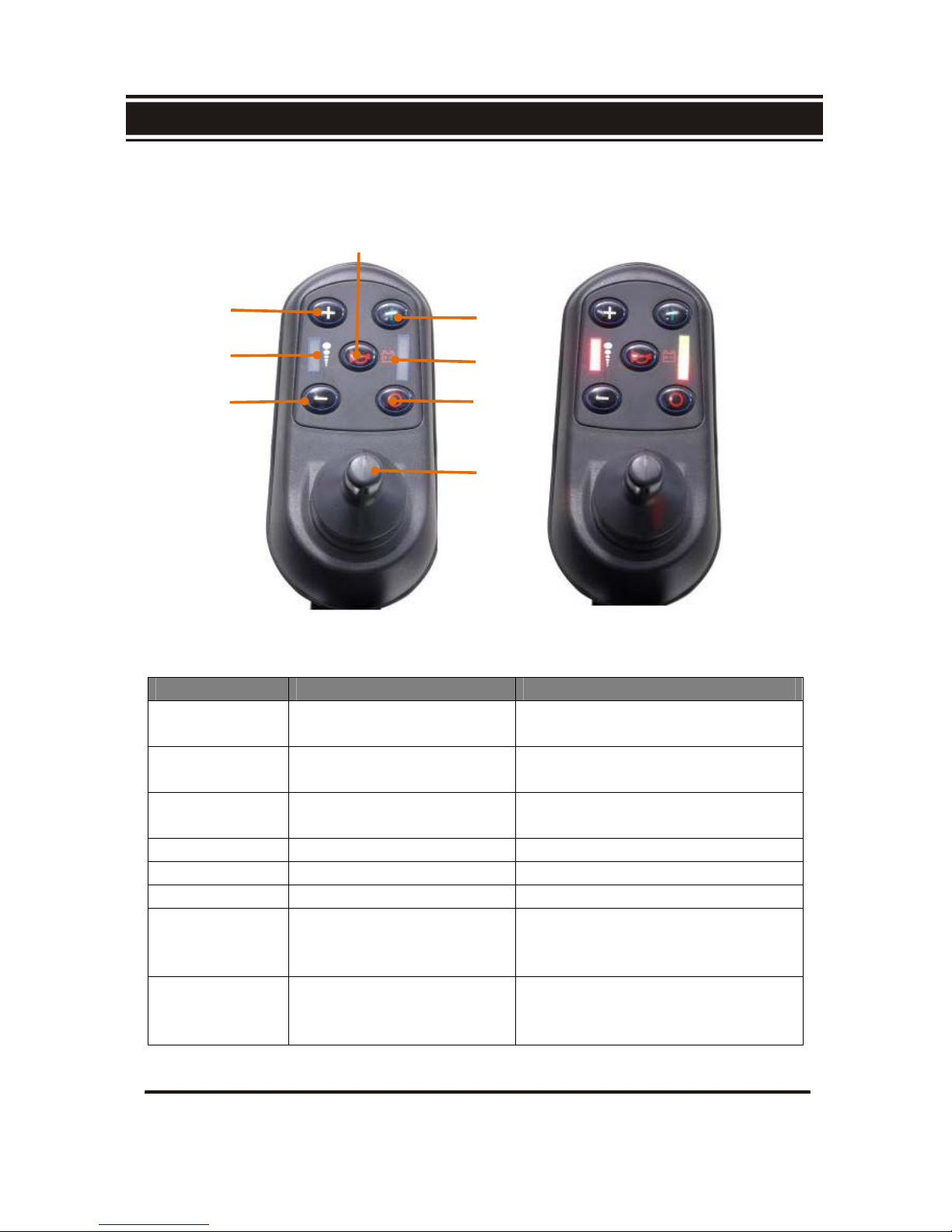
Joystick Control Panel Flashing LED light Diagnostic Indicator
Sign Problem Solution
Battery is running low Re-charge or replace both batteries immediately
Joystick cannot deliver
signals to the control module
Inspect all cables and ensure connectors are firmly
connected or replace the joystick
Batteries are being charged.
An electronic drive locking
device is engaged to prevent
the chair from operating
Disconnect the 3-pin charger cable from the
Joystick Control Panel
Brushless motors fail to
move
a) Inspect all control cables are firmly connected.
b) Inspect all control cables to see if there are any
open or short circuits by using a multimeter.
Electromagnetic brakes
disengaged
Push the electromagnetic brake lever to the “Lock”
position
Ⅳ.Troubleshooting and Solutions
8
Faulty Folding Mechanism, Armrest and Wheels
Problem Solution
Defective backrest folding arm joint
Follow below; unscrew the folding arm and
replace with a new one by securely
retightening the screws back on
Main frame fails to fold Inspect and remove possible jammed objects
within or on the frame’s folding joints
Front caster wheels malfunction
Inspect wheel nuts to ensure that they are not
loosened or that the wheel bearing is not
damaged. Securely retighten loose nuts or
replace the wheel bearing
Loosened rotating armrest
Follow below; dismantle backrest folding arm
and then remove the arm rest. Securely
retighten the loosened screws. Reinstall the
armrest assembly
Anti-Tipping wheels cannot be retracted Adjust locking screw to the appropriate
position
Ⅴ.Maintenance Guide
9
Electrical Troubleshooting – Use a Digital Multimeter
1. 5-pin XLR Plug voltage test
a. Follow below; set the multimeter to DC voltage mode. Follow below, to probe pin
#1 and pin #5 of the 5-pin XLR plug. The voltage reading should fall within the
specified range between 22V and 28V.
2. Motor’s internal short circuit or open circuit test
a. Follow below; set the multimeter to Ωresistance mode with the appropriate
resistance range, the red probe comes in contact with each pin hole of the 10-pin
plug. The black probe touches the motor housing to detect short circuits or open
circuits of the motor.
3. Battery test
a. Follow below; set the multimeter to DC mode with the appropriate voltage range.
4. 3-pin charging connector
a. Follow below; set the multimeter to Ωmode with the appropriate resistance range,
to probe each pin hole for open circuit or short circuit.