Keba KeTop Safe Wireless System User manual

KeTop
Safe Wireless System
Quick Start Guide

1
Welcome
To KeTop Safe Wireless System from KEBA
Automation by innovation
Thank you for your interest in our innovative automation solutions. Founded in 1968, KEBA is
today an internationally active company with more than 1,750 employees and enjoys a high
reputation on the world market.
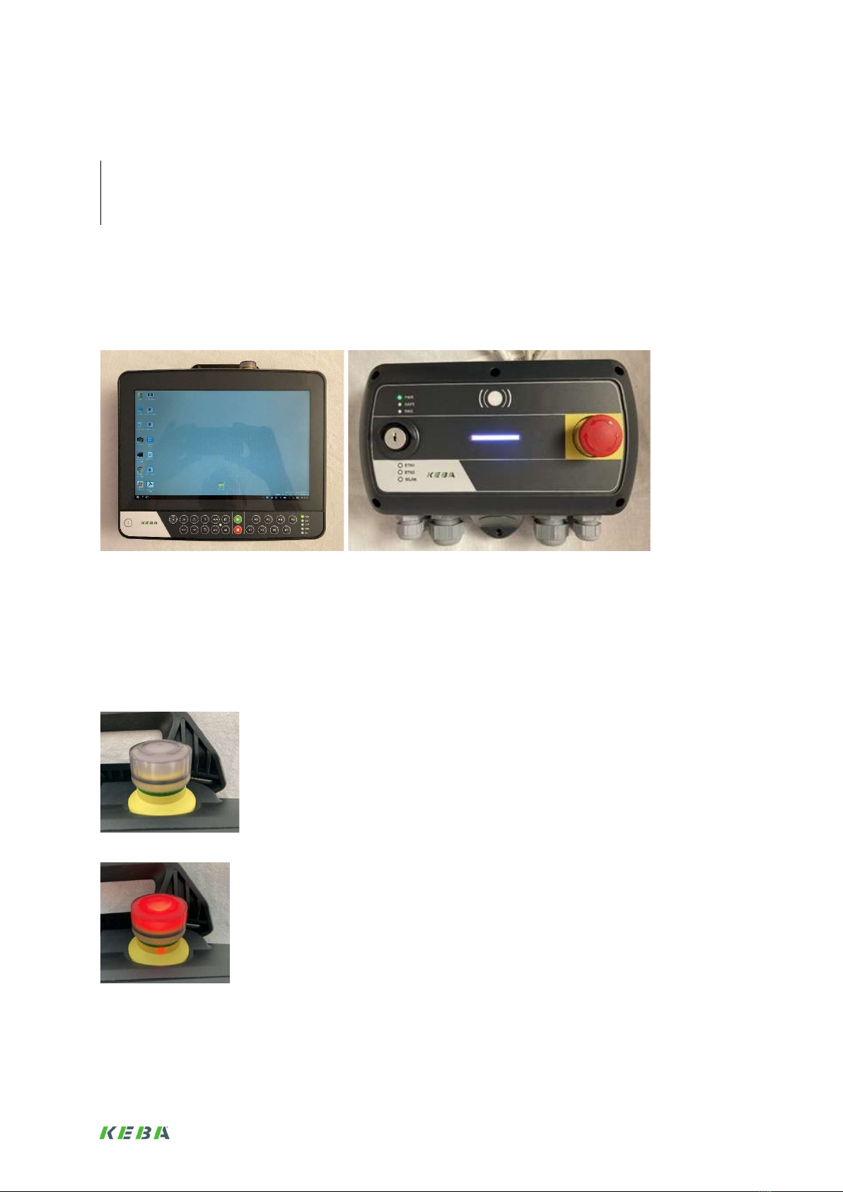
The KeTop Safe Wireless System is a solution for the safe mobile wireless operation of a plant
or a machine.
For more information, please visit our website:
www.keba.com/industrial-automation
Procedure for commissioning and operation
1. Introduction .................................................................................................................................... 3
2. System description ........................................................................................................................ 3
3. Installation ...................................................................................................................................... 4
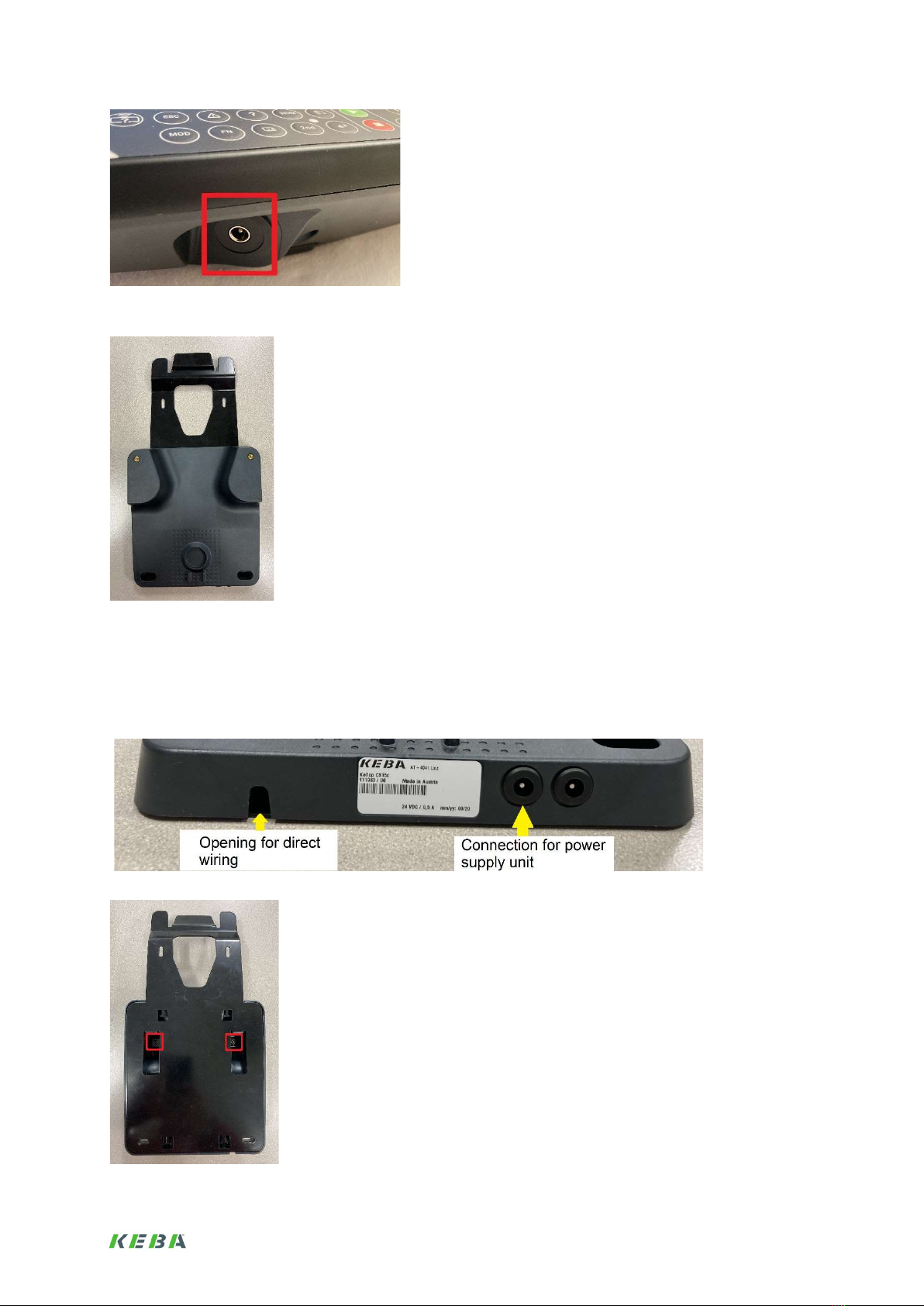
3.1. Power supply of the base station .............................................................................................. 4
3.2. Power supply of the handheld terminal ..................................................................................... 4
3.3. Loading options ......................................................................................................................... 5
3.4. Switching on the handheld terminal .......................................................................................... 7
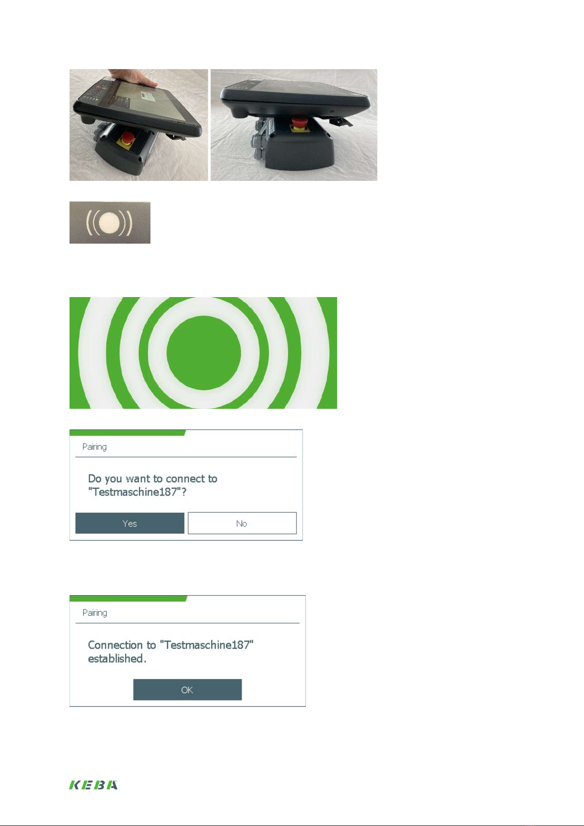
4. Connecting and disconnecting the base station and the handheld terminal .......................... 7
4.1. Connect ..................................................................................................................................... 7
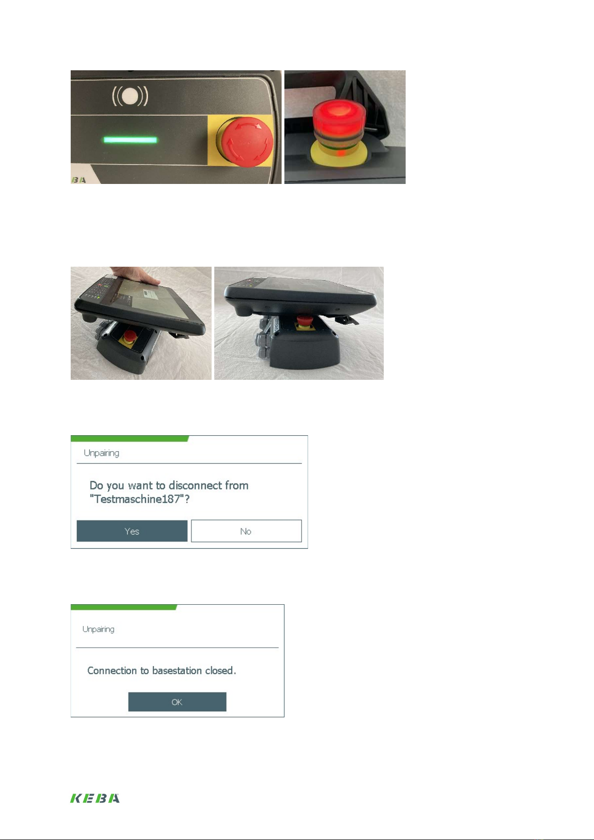
4.2. Disconnect ................................................................................................................................ 9
5. Configuration ................................................................................................................................ 10
5.1. Assign base station name ....................................................................................................... 11
5.2. Set network mode ................................................................................................................... 12
5.3. Network configuration ............................................................................................................. 15
5.4. Fast Response Operator Controls (Fast Response Buttons) ................................................. 17
6. Projection ...................................................................................................................................... 19
6.1. OperatorControlsInterfaces ..................................................................................................... 19
6.2. Access to elements of the KeTop Safe Wireless System ....................................................... 19
6.3. Data connection ...................................................................................................................... 19
7. Operation ...................................................................................................................................... 19
7.1. Ident Key ................................................................................................................................. 20
7.2. Enabling switch ....................................................................................................................... 20

2
7.3. Emergency stop ...................................................................................................................... 21
7.4. Pairing/unpairing connections ................................................................................................. 22
7.5. Remote Pairing ....................................................................................................................... 22
7.6. Remote Unpairing ................................................................................................................... 25
7.7. Error conditions during connection between base station and handheld terminal ................. 26
Used hardware
- KeTop T155WL-W10-NN1-W10E handheld terminal
- KeTop CB410-SE2
Used software
- Already installed on the base station and the handheld terminal.

3
1. Introduction
This document describes in a simplified way individual topics of the use of the KeTop Wireless
System. It does not replace the study of the project engineering manual, where the individual
topics are described and explained in detail. Information on sources of danger, hazardous
situations and the proper use must also be read there.
2. System description
The KeTop Wireless System consists of a base station and a handheld terminal.
Illustration: Base station and handheld terminal
There are two states for the handheld terminal
It is connected to a base station (paired)
It is not connected to a base station (unpaired)
The safety devices on the handheld terminal (emergency stop and enabling switch) are only active in
the paired state. The emergency stop on the base station is always available. The network with which
data is exchanged is not part of this state.
Illustration: Emergency stop not illuminated
Illustration: Emergency stop illuminated
How to switch between these two states, see chapter 4.

4
3. Installation
3.1. Power supply of the base station
First of all, the base station must be supplied with voltage. To do this, pin 10 of terminal strip S1 must
be supplied with GND and pin 11 of terminal strip S1 with 24V.
Illustration: Picture of the base station with terminal strip S1 (Pin 10 and 11)
As soon as the base station is powered, the PWR led on the base station lights up and the base
station goes into bridged emergency stop status, the bar turns white.
Illustration: PWR Led indicates power supply to the base station
3.2. Power supply of the handheld terminal
Before starting the handheld terminal for the first time, the battery must be installed in the handheld
terminal. To do this, open the cover of the battery compartment
Illustration: Rear side of the handheld terminal with marked cover of the battery compartment

5
Plug in the battery, place it in the slot and screw the cover shut with a Torx T10 screwdriver.
Illustration: Rear side of the handheld terminal with open cover of the battery compartment. The plug for the battery is marked
Then charge the battery (see next section) until the charge indicator light goes out.
Illustration: Battery charge indicator light
3.3. Loading options
Optional power supply unit directly on the handheld terminal
Power supply: Output 24V DC, DC plug adapter 5.5/2.1
Illustration: Power supply

6
Illustration: Charging socket of the handheld terminal
Optional charging station KeTop CS 15x
Illustration: Charging station KeTop CS 15x
The charging station is supplied with power either via the charging socket (data as for optional power
supply unit directly on the handheld terminal) or by direct wiring with a 24V power supply. For direct
wiring, the charging station must be opened, the screws for this are located on the back of the
charging station. A Torx T10 screwdriver is required for the screws.
For charging, the handheld terminal is hooked in at the top, please check the charging indicator light.
Illustration: Connectors of the charging station
Illustration: Rear of the charging station with the marked screws

7
Illustration: Connectors of the charging station for direct wiring
3.4. Switching on the handheld terminal
Switch on the handheld terminal using the Power key. The device is switched on as soon as the PWR
(Power) led lights up.
Illustration: Power key of the handheld terminal
Illustration: Power led on the handheld terminal
The handheld terminal will then boot Windows and a Windows desktop will appear.
4. Connecting and disconnecting the base station and
the handheld terminal
4.1. Connect
To connect, hold the handheld terminal close to the base station (<2cm). The type plate area of the
handheld terminal should be close to the RFID sign of the base station. As soon as the two devices
have recognized each other, a vibration feedback is given.

8
Illustration: Keep devices close together
Illustration: RFID sign on the base station
A waiting dialog is displayed until communication is established, then a dialog appears asking whether
a connection to the base station should be established with the name of the base station.
Illustration: Waiting dialog until communication is established
Illustration: Dialog whether a connection should be established with this base station "Testmaschine187"
If the answer is yes, the connection is established. If this connection is established, a dialog is
displayed, the bar of the base station turns green and the emergency stop is illuminated.
Illustration: Dialog confirming that the connection exists

9
Illustration: Successful establishment of the connection between base station and handheld terminal
4.2. Disconnect
To disconnect, hold the connected handheld terminal close to the base station (<2cm). The type plate
area of the handheld terminal should be close to the RFID sign of the base station.
Illustration: Keep devices close together
A dialog appears asking whether the connection to the base station should be closed by specifying the
name of the base station.
Illustration: Dialog whether the connection to the base station "Testmaschine187" is to be disconnected
If the answer is yes, the connection is closed. If this connection is closed, a dialogue is displayed, the
bar of the base station turns white and the emergency stop is no longer illuminated.
Illustration: Dialog confirming that the connection has been closed

10
Illustration: Successful closing of the connection between base station and handheld terminal
5. Configuration
To configure the base station and/or the handheld terminal, these two must first be connected (see
chapter 4). For the configuration, the DeviceConfig tool is available on the handheld terminal, with
which both the base station and the handheld terminal can be configured.
Illustration: Windows Desktop with DeviceConfig tool
After starting the DeviceConfig tool, different menus can be selected.
Illustration: Main menu DeviceConfig tool

11
5.1. Assign base station name
Each base station should be given a name. The default name is the serial number of the base station.
The name always appears when connecting and disconnecting the base station with the handheld
terminal.
Note: To be able to perform this configuration, the base station and the handheld terminal must be
connected. The connection must be established before starting the DeviceConfig tool.
Note: For the name please use only letters and numbers and no special characters.
First select the base station in the DeviceConfig tool main menu.
Illustration: DeviceConfig tool main menu
Then select the dialog for entering the name of the base station.
Illustration: Base station submenu
To enter the name, press the keyboard icon next to the name. An on-screen keyboard opens for
entering the name. The name dialog also indicates the base station to which the handheld terminal is
connected (paired). Once the name has been entered, the dialog is exited via "Write to basestation".
This command writes the name to the base station.

12
Illustration: Dialog for entering the name of the base station
Illustration: On-screen keyboard for entering text
5.2. Set network mode
Next, the Network Mode should be set, in which state of the system over which network data should
be exchanged. For this purpose the network mode can be set.
Illustration: DeviceConfig tool main menu
Illustration: Network submenu

13
Illustration: Modedialog
But what can be set here? There are different deployment scenarios for the KeTop Wireless System,
which can be configured here. In the following, the scenarios are briefly described and how they can
be configured in the DeviceConfig tool.
Scenario „Industrial tablet“:
The handheld terminal is operated in the hall network and there is no connection to a base station -
comparable to a tablet. There is only data traffic and no secure connection. In this case, no access to
information from the base station is possible.
Illustration: Scenario description „Industrial tablet“
The corresponding configuration in network mode looks like this, a connection of the handheld
terminal to the base station is not possible in this mode, the emergency stop and the enabling switch
are not available, the emergency stop will never be illuminated, a base station is not necessary.
Illustration: Configuration for scenario „Industrial tablet“
Scenario „Cable replacement“:
The handheld terminal is only operated with the base station. Data traffic only takes place if the two
have established a secure connection after being paired. In the paired state, the emergency stop and
the enabling button are available on the handheld terminal. This is indicated by the emergency stop
lighting.

14
Illustration: Scenario description „Cable replacement“
Illustration: Configuration for scenario „Cable replacement“
Scenario „HMI focus“:
The handheld terminal is only operated in paired mode with the base station. In unpaired mode, data
traffic is handled via the hall network. In the paired state, the emergency stop and the enabling button
are available on the handheld terminal. This is indicated by the emergency stop lighting.
Illustration: Scenario description scenario „HMI focus“
Illustration: Configuration for scenario „HMI focus“
Scenario „SCADA focus“:
The handheld terminal always uses the WLAN of the hall network for data traffic. The safe connection
can exist in parallel. In the paired state, the emergency stop and the enabling button are available on
the handheld terminal. This is indicated by the emergency stop lighting.

15
Illustration: Scenario description scenario „SCADA focus“
Illustration: Configuration for scenario „SCADA focus“
5.3. Network configuration
Handheld terminal network through the base station
If the base station is selected in the network mode, the connection configured here is used. From the
point of view of the network, the base station is transparent and is therefore not considered a network
subscriber. From the point of view of the application on the handheld terminal, the handheld terminal is
in the network to which the base station is connected. The SSID of the WLAN between the base
station and the handheld terminal is generated from the serial number, among other things; the
password is generated, is not visible and is exchanged between the base station and the handheld
terminal. However, the band and the channel can be parameterized from the established WLAN
connection.
Illustration: Handheld terminal in the base station network
Note: To be able to perform this configuration, the base station and the handheld terminal must be
connected. The connection must be established before starting the DeviceConfig tool.

16
Illustration: Selecting the submenu for configuring the network settings of the base station
Illustration: Submenu for configuring the network settings of the base station
Illustration: Setting the network settings of the base station
Illustration: Parameterization of the WLAN connection between base station and handheld terminal
Network of the handheld terminal in the hall network
If the hall is selected in network mode, the connection configured here is used. The WLAN connection
between the hall and the handheld terminal must be configured as follows.

17
Illustration: Handheld terminal in the hall network
Illustration: Selecting the submenu for configuring the hall network settings
Illustration: Setting the hall network settings
5.4. Fast Response Operator Controls (Fast Response Buttons)
[Option]
Fast Response Operator Controls are a function where the operator controls of the handheld terminal
are directly assigned to outputs of the base station and the value of the controls can be tapped directly
at the outputs during operation. Currently this is only implemented for the keys.
The outputs are in the base station at the terminal strip Fast Response Buttons Pin 6 (DO14) to Pin 20
(DO1), whereby Pin 5 and Pin 11 provide GND..

18
Illustration: Image of the base station with terminal strip Fast Response Buttons (Pin 5 to 20)
The configuration is then done in the DeviceConfig tool.
Note: To be able to perform this configuration, the base station and the handheld terminal must be
connected. The connection must be established before starting the DeviceConfig tool.
Illustration: DeviceConfig tool main menu
Then select the Fast Response Buttons configuration dialog..
Illustration: Base station submenu
The configuration is done in such a way that for each of the outputs used (DO), it is defined which key
of the handheld terminal switches it. For definition, press the "KEY" button next to the key number and
then press the desired key. The scancode of the key is filled.

19
Illustration: Dialog for configuring the Fast Response buttons.
6. Projection
For the projection of the visualization application, the KeTop Safe Wireless System is the same as a
wired KeTop system. Both the access via control interfaces to the operator controls and the
connection with PLCs, computers or other data sources is made via the network connections. It should
only be noted that when switching between the two network options, connections are interrupted and
must be reestablished.
6.1. OperatorControlsInterfaces
Refer to the manual of the respective controller connection to the operator controls.
6.2. Access to elements of the KeTop Safe Wireless System
The elements of the KeTop Safe Wireless System can be accessed via the HWApi. This library is
supplied as a DLL and can be used in C, C++ and C# implemented applications. Further information is
available from KEBA Support.
6.3. Data connection
See the manual for the respective visualization projection or programming.
7. Operation
During operation, the base station and handheld terminal are normally connected or disconnected
depending on the usage scenario. This is described in chapter 4. If it is necessary to check to which
base station a handheld terminal is connected, it is possible to check this via the Ident Key.
Another application is the pressing of the emergency stop or the enabling switch during operation. This
activates electrical safety mechanisms; when the emergency stop is pressed, this is also visualized by
the base station.
For exceptional situations where the base station and the handheld terminal cannot be brought into
close proximity, there is a function for connecting or disconnecting both devices "remotely" (remote
pairing and remote unpairing). However, a line of sight must always be available between the two
devices.
Table of contents
Other Keba Control System manuals
Popular Control System manuals by other brands

A1S Group
A1S Group Evo1-MCP 1 Technical manual

heat-timer
heat-timer DiGi-SPAN Elite Series Installation and operation manual

MUELLER CO.
MUELLER CO. Hydro-guard Operating instructions manual

Siemens
Siemens SINUMERIK 840D sl Commissioning manual

LECHO
LECHO V-Max manual

IntelligentAg
IntelligentAg Engage Zone Control Operator's guide

EWC Controls
EWC Controls ULTRA-ZONE RD-HD Application note

Safety Xpress
Safety Xpress REMBOLSMU PRODUCT INFORMATION & INSTALLATION GUIDE

Mente Marine
Mente Marine ACS R/RP user manual

YASKAWA
YASKAWA YASNAC i80 Maintenance manual

Honeywell
Honeywell W180 user manual

Motorline professional
Motorline professional MPIE10 Assembly and operating manual