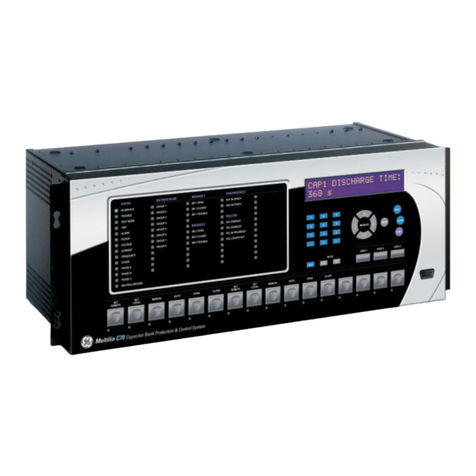
GE TRANSFORMER MANAGEMENT RELAY 745 User manual

745
TRANSFORMER MANAGEMENT RELAY™
INSTRUCTION MANUAL
Firmware Revision: 280.000
Manual P/N: 1601-0070-B6 (GEK-106292D)
Copyright © 2008 GE Multilin
GE Multilin
215 Anderson Avenue, Markham, Ontario
Canada L6E 1B3
Tel: (905) 294-6222 Fax: (905) 201-2098
Internet: http://www.GEindustrial.com/multilin
Manufactured under an
ISO9001 Registered system.
LISTED
52TL
IND.CONT. EQ.
E83849
745 Transformer Management Relay ™
814768AG.CDR
IN SERVICE
LOCAL
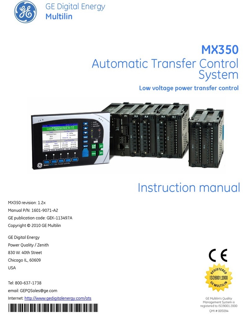
SETPOINT GROUP 2
LOAD-LIMIT
REDUCED
TRIP
SELF-TEST
ERROR
SETPOINT GROUP 3
TRANSFORMER
DE-ENERGIZED
ALARM
PICKUP
TEST MODE
TRANSFORMER
OVERLOAD
SETPOINT GROUP 1 PHASE A
PHASE B
PHASE C
GROUNDMESSAGE
PROGRAM PORT SETPOINT 789
456
12 3
.0HELP
MESSAGE
VALUE
ACTUAL
ESCAPE
ENTER
RESET
NEXT
DIFFERENTIAL
BLOCKED
745 STATUS SYSTEM STATUS CONDITIONS
SETPOINT GROUP 4
g
745 TRANSFORMER
MANAGEMENT RELAY
g
GE Industrial Systems
Title Page
Courtesy of NationalSwitchgear.com

GE Multilin 745 Transformer Management Relay iii
TABLE OF CONTENTS
1. PRODUCT OVERVIEW 1.1 INTRODUCTION
1.1.1 DESCRIPTION................................................................................................... 1-1
1.1.2 PROTECTION FEATURES SUMMARY ............................................................ 1-1
1.1.3 ORDER CODES ................................................................................................ 1-3
1.2 SPECIFICATIONS
1.2.1 APPLICABILITY ................................................................................................. 1-4
1.2.2 INPUTS .............................................................................................................. 1-4
1.2.3 PROTECTION ELEMENTS ............................................................................... 1-5
1.2.4 OUTPUTS .......................................................................................................... 1-7
1.2.5 MISCELLANEOUS............................................................................................. 1-7
2. GETTING STARTED 2.1 USING THE FRONT PANEL DISPLAY
2.1.1 MANEUVERING ................................................................................................ 2-1
2.1.2 CHANGING SETPOINTS .................................................................................. 2-2
2.2 SECURITY
2.2.1 INSTALLATION.................................................................................................. 2-5
2.2.2 CHANGING THE PASSCODE........................................................................... 2-5
2.2.3 DISABLING AND ENABLING PASSCODE SECURITY .................................... 2-6
3. INSTALLATION 3.1 DRAWOUT CASE
3.1.1 CASE DESCRIPTION........................................................................................ 3-1
3.1.2 PANEL CUTOUT ............................................................................................... 3-1
3.1.3 CASE MOUNTING ............................................................................................. 3-2
3.1.4 UNIT WITHDRAWAL AND INSERTION ............................................................ 3-2
3.2 TYPICAL WIRING
3.2.1 DESCRIPTION................................................................................................... 3-4
3.2.2 REAR TERMINAL LAYOUT............................................................................... 3-4
3.2.3 WIRING DIAGRAMS.......................................................................................... 3-6
3.2.4 PHASE SEQUENCE AND TRANSFORMER POLARITY.................................. 3-8
3.2.5 AC CURRENT TRANSFORMER INPUTS......................................................... 3-8
3.2.6 AC VOLTAGE INPUT ........................................................................................ 3-9
3.2.7 LOGIC INPUTS.................................................................................................. 3-9
3.2.8 CONTROL POWER ......................................................................................... 3-10
3.2.9 ANALOG INPUT .............................................................................................. 3-10
3.2.10 TAP POSITION INPUT .................................................................................... 3-10
3.2.11 RTD DRIVER/SENSOR ................................................................................... 3-11
3.2.12 OUTPUT RELAYS ........................................................................................... 3-11
3.2.13 SOLID STATE TRIP OUTPUT......................................................................... 3-11
3.2.14 ANALOG OUTPUTS ........................................................................................ 3-11
3.2.15 RS485 / RS422 COMMUNICATIONS.............................................................. 3-12
3.2.16 RS232 FRONT PANEL PROGRAM PORT ..................................................... 3-13
3.2.17 IRIG-B .............................................................................................................. 3-14
3.2.18 DIELECTRIC STRENGTH TESTING .............................................................. 3-14
4. HUMAN INTERFACES 4.1 HARDWARE INTERFACE
4.1.1 FRONT PANEL .................................................................................................. 4-1
4.1.2 DISPLAY ............................................................................................................ 4-1
4.1.3 LEDS.................................................................................................................. 4-2
4.1.4 LED INDICATORS ............................................................................................. 4-2
4.1.5 PROGRAM PORT.............................................................................................. 4-3
4.1.6 KEYPAD............................................................................................................. 4-3
4.2 745PC SOFTWARE INTERFACE
4.2.1 OVERVIEW........................................................................................................ 4-5
4.2.2 REQUIREMENTS .............................................................................................. 4-5
4.2.3 TOOLBAR AND MENUS ................................................................................... 4-5
4.2.4 HARDWARE CONFIGURATION ....................................................................... 4-6
Table of Contents
Courtesy of NationalSwitchgear.com

iv 745 Transformer Management Relay GE Multilin
TABLE OF CONTENTS
4.2.5 745PC INSTALLATION ......................................................................................4-8
4.2.6 STARTUP AND COMMUNICATIONS CONFIGURATION.................................4-9
4.2.7 USING 745PC ..................................................................................................4-10
5. SETPOINTS 5.1 OVERVIEW
5.1.1 SETPOINT MESSAGE MAP ..............................................................................5-1
5.1.2 SETPOINT ENTRY.............................................................................................5-4
5.1.3 SETPOINT WRITE ACCESS .............................................................................5-4
5.2 AUTO-CONFIGURATION
5.2.1 INTRODUCTION ................................................................................................5-5
5.2.2 DYNAMIC CT RATIO MISMATCH CORRECTION ............................................5-5
5.2.3 PHASE SHIFTS ON THREE-PHASE TRANSFORMERS..................................5-7
5.2.4 PHASE ANGLE CORRECTION .........................................................................5-8
5.2.5 ZERO-SEQUENCE COMPONENT REMOVAL..................................................5-9
5.2.6 TRANSFORMER TYPES .................................................................................5-10
5.2.7 PHASE SHIFTS................................................................................................5-22
5.3 S1 745 SETUP
5.3.1 PASSCODE ......................................................................................................5-23
5.3.2 PREFERENCES...............................................................................................5-23
5.3.3 COMMUNICATIONS ........................................................................................5-24
5.3.4 DNP COMMUNICATIONS................................................................................5-25
5.3.5 RESETTING .....................................................................................................5-26
5.3.6 CLOCK .............................................................................................................5-26
5.3.7 DEFAULT MESSAGES ....................................................................................5-27
5.3.8 SCRATCHPAD .................................................................................................5-27
5.3.9 INSTALLATION ................................................................................................5-28
5.3.10 UPGRADE OPTIONS .......................................................................................5-28
5.4 S2 SYSTEM SETUP
5.4.1 DESCRIPTION .................................................................................................5-29
5.4.2 TRANSFORMER ..............................................................................................5-29
5.4.3 WINDING..........................................................................................................5-31
5.4.4 ONLOAD TAP CHANGER................................................................................5-32
5.4.5 HARMONICS....................................................................................................5-32
5.4.6 FLEXCURVES™ ..............................................................................................5-33
5.4.7 VOLTAGE INPUT .............................................................................................5-33
5.4.8 AMBIENT TEMPERATURE..............................................................................5-34
5.4.9 ANALOG INPUT ...............................................................................................5-35
5.4.10 DEMAND METERING ......................................................................................5-36
5.4.11 ANALOG OUTPUTS.........................................................................................5-37
5.5 S3 LOGIC INPUTS
5.5.1 DESCRIPTION .................................................................................................5-38
5.5.2 LOGIC INPUTS 1 TO 16 ..................................................................................5-38
5.5.3 VIRTUAL INPUTS ............................................................................................5-38
5.6 S4 ELEMENTS
5.6.1 INTRODUCTION TO ELEMENTS....................................................................5-39
5.6.2 SETPOINT GROUP..........................................................................................5-40
5.6.3 DIFFERENTIAL ELEMENT ..............................................................................5-40
5.6.4 INSTANTANEOUS DIFFERENTIAL.................................................................5-48
5.6.5 PHASE OVERCURRENT.................................................................................5-49
5.6.6 NEUTRAL OVERCURRENT ............................................................................5-56
5.6.7 GROUND OVERCURRENT .............................................................................5-59
5.6.8 RESTRICTED GROUND (DIFFERENTIAL GROUND) ....................................5-62
5.6.9 NEGATIVE SEQUENCE OVERCURRENT......................................................5-65
5.6.10 FREQUENCY ...................................................................................................5-68
5.6.11 OVEREXCITATION ..........................................................................................5-73
5.6.12 HARMONICS....................................................................................................5-77
5.6.13 INSULATION AGING / LOSS OF LIFE ............................................................5-80
5.6.14 ANALOG LEVEL...............................................................................................5-84
5.6.15 CURRENT DEMAND........................................................................................5-85
5.6.16 TRANSFORMER OVERLOAD .........................................................................5-86
5.6.17 TAP CHANGER FAILURE................................................................................5-87
Courtesy of NationalSwitchgear.com

GE Multilin 745 Transformer Management Relay v
TABLE OF CONTENTS
5.7 S5 OUTPUTS
5.7.1 DESCRIPTION................................................................................................. 5-88
5.7.2 INTRODUCTION TO FLEXLOGIC™............................................................... 5-88
5.7.3 FLEXLOGIC™ RULES .................................................................................... 5-89
5.7.4 OUTPUT RELAYS ........................................................................................... 5-90
5.7.5 TRACE MEMORY............................................................................................ 5-92
5.7.6 VIRTUAL OUTPUTS........................................................................................ 5-93
5.7.7 TIMERS............................................................................................................ 5-93
5.8 S6 TESTING
5.8.1 DESCRIPTION................................................................................................. 5-94
5.8.2 OUTPUT RELAYS ........................................................................................... 5-94
5.8.3 ANALOG OUTPUTS ........................................................................................ 5-94
5.8.4 SIMULATION ................................................................................................... 5-95
5.8.5 FACTORY SERVICE ....................................................................................... 5-98
6. ACTUAL VALUES 6.1 OVERVIEW
6.1.1 MESSAGE MAP................................................................................................. 6-1
6.1.2 DESCRIPTION................................................................................................... 6-2
6.2 A1 STATUS
6.2.1 DATE AND TIME ............................................................................................... 6-3
6.2.2 LOGIC INPUTS.................................................................................................. 6-3
6.2.3 VIRTUAL INPUTS.............................................................................................. 6-3
6.2.4 OUTPUT RELAYS ............................................................................................. 6-3
6.2.5 VIRTUAL OUTPUTS.......................................................................................... 6-4
6.2.6 SELF-TEST ERRORS ....................................................................................... 6-4
6.3 A2 METERING
6.3.1 CURRENT.......................................................................................................... 6-5
6.3.2 HARMONIC CONTENT ..................................................................................... 6-8
6.3.3 FREQUENCY................................................................................................... 6-10
6.3.4 TAP CHANGER ............................................................................................... 6-10
6.3.5 VOLTAGE ........................................................................................................ 6-10
6.3.6 DEMAND.......................................................................................................... 6-10
6.3.7 AMBIENT TEMPERATURE ............................................................................. 6-11
6.3.8 LOSS OF LIFE ................................................................................................. 6-12
6.3.9 ANALOG INPUT .............................................................................................. 6-12
6.3.10 POWER............................................................................................................ 6-12
6.3.11 ENERGY .......................................................................................................... 6-13
6.4 A3 EVENT RECORDER
6.4.1 EVENT DATA CLEAR...................................................................................... 6-14
6.4.2 EVENT RECORDS .......................................................................................... 6-14
6.5 A4 PRODUCT INFO
6.5.1 TECHNICAL SUPPORT .................................................................................. 6-17
6.5.2 REVISION CODES .......................................................................................... 6-17
6.5.3 CALIBRATION ................................................................................................. 6-17
6.6 TARGET AND FLASH MESSAGES
6.6.1 TARGET MESSAGES ..................................................................................... 6-18
6.6.2 SELF-TEST ERRORS ..................................................................................... 6-19
6.6.3 FLASH MESSAGES ........................................................................................ 6-20
7. COMMUNICATIONS 7.1 OVERVIEW
7.1.1 PROTOCOLS..................................................................................................... 7-1
7.1.2 PHYSICAL LAYER............................................................................................. 7-1
7.2 MODBUS PROTOCOL
7.2.1 DESCRIPTION................................................................................................... 7-2
7.2.2 GE MULTILIN MODBUS IMPLEMENTATION................................................... 7-2
7.2.3 ELECTRICAL INTERFACE................................................................................ 7-2
7.2.4 DATA FRAME FORMAT AND DATA RATE ...................................................... 7-2
7.2.5 DATA PACKET FORMAT .................................................................................. 7-3
Courtesy of NationalSwitchgear.com

vi 745 Transformer Management Relay GE Multilin
TABLE OF CONTENTS
7.2.6 CRC-16 ALGORITHM ........................................................................................7-4
7.2.7 MESSAGE TIMING ............................................................................................7-4
7.3 MODBUS FUNCTIONS
7.3.1 SUPPORTED MODBUS FUNCTIONS...............................................................7-5
7.3.2 EXCEPTION RESPONSES................................................................................7-8
7.3.3 READING THE EVENT RECORDER.................................................................7-8
7.3.4 READING TRACE MEMORY .............................................................................7-9
7.3.5 ACCESSING DATA VIA THE USER MAP .........................................................7-9
7.3.6 FUNCTION CODE SUBSTITUTIONS ..............................................................7-11
7.3.7 MEMORY MAP ORGANIZATION.....................................................................7-12
7.4 MODBUS MEMORY MAP
7.4.1 745 MEMORY MAP..........................................................................................7-13
7.4.2 MEMORY MAP DATA FORMATS....................................................................7-48
7.5 DNP COMMUNICATIONS
7.5.1 DEVICE PROFILE DOCUMENT ......................................................................7-61
7.5.2 IMPLEMENTATION TABLE .............................................................................7-63
7.5.3 DNP POINT LISTS ...........................................................................................7-64
8. COMMISSIONING 8.1 GENERAL
8.1.1 INTRODUCTION ................................................................................................8-1
8.1.2 TESTING PHILOSOPHY ....................................................................................8-1
8.1.3 SAFETY PRECAUTIONS...................................................................................8-2
8.1.4 CONVENTIONS .................................................................................................8-2
8.1.5 TEST EQUIPMENT ............................................................................................8-3
8.2 PRELIMINARY WORK
8.2.1 DESCRIPTION ...................................................................................................8-4
8.2.2 DIELECTRIC STRENGTH TESTING .................................................................8-5
8.3 LOGIC INPUTS AND OUTPUT RELAYS
8.3.1 LOGIC INPUTS ..................................................................................................8-6
8.3.2 OUTPUT RELAYS..............................................................................................8-6
8.4 DISPLAY, METERING, COMMUNICATIONS, AND ANALOG OUTPUTS
8.4.1 DESCRIPTION ...................................................................................................8-7
8.4.2 CURRENT INPUTS ............................................................................................8-7
8.4.3 VOLTAGE INPUT ...............................................................................................8-8
8.4.4 TRANSFORMER TYPE SELECTION ................................................................8-8
8.4.5 AMBIENT TEMPERATURE INPUT....................................................................8-9
8.4.6 ANALOG OUTPUTS.........................................................................................8-11
8.4.7 TAP POSITION.................................................................................................8-11
8.5 PROTECTION SCHEMES
8.5.1 PRECAUTIONS ................................................................................................8-12
8.5.2 HARMONIC RESTRAINED PERCENT DIFFERENTIAL .................................8-12
8.5.3 INSTANTANEOUS DIFFERENTIAL PROTECTION ........................................8-17
8.5.4 PHASE TIME OVERCURRENT .......................................................................8-17
8.5.5 PHASE INSTANTANEOUS OVERCURRENT .................................................8-19
8.5.6 NEUTRAL TIME OVERCURRENT...................................................................8-20
8.5.7 NEUTRAL INSTANTANEOUS OVERCURRENT.............................................8-21
8.5.8 GROUND TIME OVERCURRENT....................................................................8-22
8.5.9 GROUND INSTANTANEOUS OVERCURRENT..............................................8-24
8.5.10 RESTRICTED GROUND FAULT......................................................................8-25
8.5.11 NEGATIVE SEQUENCE TIME OVERCURRENT ............................................8-27
8.5.12 NEGATIVE SEQUENCE INSTANTANEOUS OVERCURRENT ......................8-28
8.5.13 FREQUENCY ...................................................................................................8-29
8.5.14 OVEREXCITATION ..........................................................................................8-34
8.5.15 INSULATION AGING........................................................................................8-35
8.5.16 TAP MONITOR FAILURE.................................................................................8-35
8.6 AUXILIARY PROTECTION AND MONITORING FUNCTIONS
8.6.1 THD LEVEL SCHEME......................................................................................8-36
8.6.2 HARMONIC DERATING FUNCTION ...............................................................8-37
8.6.3 TRANSFORMER OVERLOAD .........................................................................8-37
Courtesy of NationalSwitchgear.com

GE Multilin 745 Transformer Management Relay vii
TABLE OF CONTENTS
8.7 PLACING THE RELAY INTO SERVICE
8.7.1 PROCEDURE .................................................................................................. 8-38
A. APPENDIX A.1 EU DECLARATION
A.1.1 DECLARATION OF CONFORMITY ..................................................................A-1
A.2 WARRANTY
A.2.1 GE MULTILIN WARRANTY ...............................................................................A-2
Courtesy of NationalSwitchgear.com

GE Multilin 745 Transformer Management Relay 1-1
1 PRODUCT OVERVIEW 1.1 INTRODUCTION
1
1 PRODUCT OVERVIEW 1.1INTRODUCTION 1.1.1 DESCRIPTION
These instructions do not purport to cover all details or variations in equipment nor provide for every possible con-
tingency to be met in connection with installation, operation, or maintenance. Should further information be desired
or should particular problems arise which are not covered sufficiently for the purchaser’s purpose, the matter
should be referred to the General Electric Company.
To the extent required the products described herein meet applicable ANSI, IEEE, and NEMA standards; but no
such assurance is given with respect to local codes and ordinances because they vary greatly.
The 745 Transformer Management Relay™ is a high speed, multi-processor based, three-phase, two or three winding,
transformer management relay intended for the primary protection and management of small, medium and large power
transformers. The 745 combines Percent Differential, Overcurrent, Frequency, and Overexcitation protection elements
along with monitoring of individual harmonics, and THD in one economical package.
The relay provides a variety of adaptive relaying features:
• Adaptive Harmonic Restraint which addresses the problem of false tripping during inrush
• Adaptive Time Overcurrent Elements which will adjust their pickup settings based on the calculated transformer capa-
bility when supplying load currents with high harmonic content
• Multiple Setpoint Groups which allow the user to enter and dynamically select from up to four groups of relay settings
to address the protection requirements of different power system configurations
• Dynamic CT Ratio Mismatch Correction which monitors the on-load tap position and automatically corrects for CT ratio
mismatch
• FlexLogic™ which allows PLC style equations based on logic inputs and protection elements to be assigned to any of
the 745 outputs.
The 745 also includes a powerful testing and simulation feature. This allows the protection engineer the ability to test the
relay operation based on captured or computer generated waveform data which can be converted to a digitized format and
downloaded into the 745’s simulation buffer for “playback”. A Waveform Capture function that records waveform data for
fault, inrush, or alarm conditions is also provided.
The Auto-Configuration function eliminates the need for any special CT connections by having all CTs connected in wye.
1.1.2 PROTECTION FEATURES SUMMARY
SYMBOL COMMON PROTECTION ELEMENT SYMBOL WINDING 1 PROTECTION ELEMENT
59/81-1 Volts-Per-Hertz 1 150/46 Negative Sequence Instantaneous Overcurrent
59/81-2 Volts-Per-Hertz 2 151/46 Negative Sequence Time Overcurrent
81U-1 Underfrequency 1 150P1 Phase Instantaneous Overcurrent 1
81U-2 Underfrequency 2 150P2 Phase Instantaneous Overcurrent 2
81U-R1 Frequency Decay Rate 1 150N1 Neutral (3I0) Instantaneous Overcurrent 1
81U-R2 Frequency Decay Rate 2 150N2 Neutral (3I0) Instantaneous Overcurrent 2
81U-R3 Frequency Decay Rate 3 150G1 Ground Instantaneous Overcurrent 1
81U-R4 Frequency Decay Rate 4 150G2 Ground Instantaneous Overcurrent 2
81-H5 5th Harmonic Level 151P Phase Time Overcurrent
81O Overfrequency 151N Neutral (3I0) Time Overcurrent
87 Differential (Percent) 151G Ground Time Overcurrent
50/87 Instantaneous Differential 187TG Ground Differential (Restricted Ground Fault)
AN-1 Analog Input Level 1 1THD Total Harmonic Distortion Level
AN-2 Analog Input Level 2 1AD Current Demand
Insulation Aging:
• Aging Factor
• Hottest Spot Limit
• Total Accumulated Life
Tap Changer Monitor
NOTE
Courtesy of NationalSwitchgear.com

1-2 745 Transformer Management Relay GE Multilin
1.1 INTRODUCTION 1 PRODUCT OVERVIEW
1
Figure 1–1: SINGLE LINE DIAGRAM
SYMBOL WINDING 2 PROTECTION ELEMENT SYMBOL WINDING 3 PROTECTION ELEMENT
250/46 Negative Sequence Instantaneous Overcurrent 350/46 Negative Sequence Instantaneous Overcurrent
251/46 Negative Sequence Time Overcurrent 351/46 Negative Sequence Time Overcurrent
250P1 Phase Instantaneous Overcurrent 1 350P1 Phase Instantaneous Overcurrent 1
250P2 Phase Instantaneous Overcurrent 2 350P2 Phase Instantaneous Overcurrent 2
250N1 Neutral (3I0) Instantaneous Overcurrent 1 350N1 Neutral (3I0) Instantaneous Overcurrent 1
250N2 Neutral (3I0) Instantaneous Overcurrent 2 350N2 Neutral (3I0) Instantaneous Overcurrent 2
250G1 Ground Instantaneous Overcurrent 1 351P Phase Time Overcurrent
250G2 Ground Instantaneous Overcurrent 2 351N Neutral (3I0) Time Overcurrent
251P Phase Time Overcurrent 351G Ground Time Overcurrent
251N Neutral (3I0) Time Overcurrent 387TG Ground Differential (Restricted Ground Fault)
251G Ground Time Overcurrent 3THD Total Harmonic Distortion Level
287TG Ground Differential (Restricted Ground Fault) 3AD Current Demand
2THD Total Harmonic Distortion Level
2AD Current Demand
Courtesy of NationalSwitchgear.com

GE Multilin 745 Transformer Management Relay 1-3
1 PRODUCT OVERVIEW 1.1 INTRODUCTION
1
1.1.3 ORDER CODES
Table 1–1: 745 ORDER CODES
745 –––––
BASE UNIT 745 | | | ||
745 Transformer Management Relay
WINDINGS PER
PHASE W2 ||| | Two windings per phase
W3 ||| | Three windings per phase
PHASE
CURRENT INPUT
RATINGS
P1 | ||
Winding 1 = 1 A, Winding 2 = 1 A, Winding 3 = 1 A (if applicable)
P5 | ||
Winding 1 = 5 A, Winding 2 = 5 A, Winding 3 = 5 A (if applicable)
P15 | ||
Winding 1 = 1 A, Winding 2 = 5 A
P51 | ||
Winding 1 = 5 A, Winding 2 = 1 A
P115 | ||
Winding 1 = 1 A, Winding 2 = 1 A, Winding 3 = 5 A
P151 | ||
Winding 1 = 1 A, Winding 2 = 5 A, Winding 3 = 1 A
P155 | ||
Winding 1 = 1 A, Winding 2 = 5 A, Winding 3 = 5 A
P511 | ||
Winding 1 = 5 A, Winding 2 = 1 A, Winding 3 = 1 A
P515 | ||
Winding 1 = 5 A, Winding 2 = 1 A, Winding 3 = 5 A
P551 | ||
Winding 1 = 5 A, Winding 2 = 5 A, Winding 3 = 1 A
GROUND
CURRENT INPUT
RATINGS
G1 | | Winding 1/2 = 1 A, Winding 2/3 = 1 A
G5 | | Winding 1/2 = 5 A, Winding 2/3 = 5 A
G15 | | Winding 1/2 = 1 A, Winding 2/3 = 5 A
G51 | | Winding 1/2 = 5 A, Winding 2/3 = 1 A
CONTROL
POWER
LO |40 to 60 V DC; 20 to 48 V AC at 48 to 62 Hz
HI |90 to 300 V DC; 70 to 265 V AC at 48 to 62 Hz
OPTIONS AAnalog Inputs/Outputs
LLoss of Life
RRestricted Ground Fault
Courtesy of NationalSwitchgear.com
1-4 745 Transformer Management Relay GE Multilin
1.2 SPECIFICATIONS 1 PRODUCT OVERVIEW
1
1.2SPECIFICATIONS 1.2.1 APPLICABILITY
Transformers: 2 Winding or 3 Winding Frequency: 50 or 60 Hz nominal
(frequency tracking allows operation
from 2 to 65 Hz)
1.2.2 INPUTS
CONTROL POWER
Options: LO/HI (specified when ordering)
LO Range: DC = 20 to 60 V;
AC = 20 to 48 V at 48 to 62 Hz
HI Range: DC = 90 to 300 V;
AC = 70 to 265 V at 48 to 62 Hz
Power: 30 VA nominal, 40 VA maximum
Fuse (not accessible)
Current Rating: 3.15 A
Type: 5 × 20 mm Slow-Blow Littelfuse, High
Breaking Capacity; Model # 2153.15
PHASE CURRENT INPUT
Source CT: 1 to 50000 A primary
1 or 5 A secondary
Relay Input: 1 A or 5 A (specified when ordering)
Burden: Less than 0.2 VA at rated load per phase
Conversion Range: 0.02 to 46 ×CT
Accuracy:
at <4 ×CT: ± 0.25% of 4 ×CT (±0.01 ×CT)
at ≥4 ×CT: ± 0.5% of 46 ×CT (±0.2 ×CT)
Overload Withstand: 1 second at 80 times rated current
2 seconds at 40 times rated current
continuous at 3 times rated current
GROUND CURRENT INPUT
Source CT: 1 to 50000 A primary
1 or 5 A secondary
Relay Input: 1 A or 5 A (specified when ordering)
Burden: Less than 0.2 VA at rated load
Conversion Range: 0.02 to 46 ×CT
Accuracy:
at <4 ×CT: ± 0.25% of 4 ×CT (±0.01 ×CT)
at ≥4 ×CT: ± 0.5% of 46 ×CT (±0.2 ×CT)
Overload Withstand: 1 second at 80 times rated current
2 seconds at 40 times rated current
continuous at 3 times rated current
VOLTAGE INPUTS
Source VT: 2 to 600 kV / 60 to 120 V
Source VT Ratio: 1 to 5000 in steps of 1
Relay Input: 60 V to 120 V phase-neutral
Burden: Less than 0.025 VA at 120 V
Max. Continuous: 273 V
Accuracy: ±1% of 2 ×VT (±0.02 ×VT)
LOGIC INPUTS
Number of Inputs: 16
Dry Contacts: 1000 Ωmaximum ON resistance
(32 V DC at 2 mA provided by 745)
Wet Contacts: 30 to 300 V DC at 1.5 mA
ANALOG INPUT
Type: DC mA
Ranges: 0 to 1 mA, 0 to 5 mA, 0 to 10 mA,
0 to 20 mA, 4 to 20 mA (programmable)
Input Impedance: 375 Ω±10%
Conversion Range: 0 to 21 mA
Accuracy: ±1% of full scale (based on input range)
TAP POSITION
Type: resistance (ohms)
Range: 0 to 500 Ωor 0.5 to 5.0 kΩ
Bias Current: 1 mA or 10 mA (based on input range)
Accuracy: ±1% of full scale (based on input range)
RTD
Type: 3 wire
RTD Type 100 ΩPlatinum (DIN.43760),
100 ΩNickel, 120 ΩNickel
IRIG-B INPUT
Amplitude-Modulated: 1.0 to 10 V pk-pk
DC Shift: TTL
Input Impedance 70 to 100 kΩ
Courtesy of NationalSwitchgear.com
GE Multilin 745 Transformer Management Relay 1-5
1 PRODUCT OVERVIEW 1.2 SPECIFICATIONS
1
1.2.3 PROTECTION ELEMENTS
PERCENT DIFFERENTIAL
Operating Current Pkp: 0.05 to 1.00 ×CT in steps of 0.01
Dropout Level: 97 to 98% of Pickup
SLOPE-1 Range: 15% to 100% in steps of 1
SLOPE-2 Range: 50% to 100% in steps of 1
KP (Slope-1 Kneepoint): 1.0 to 20.0 ×CT in steps of 0.1
Harmonic Restraint: 0.1% to 65.0% in steps of 0.1
Solid State Output Operate Time:
at Pickup < 1 ×CT: 42 to 52 ms
at 1 ×CT < Pickup < 1.1 ×kneepoint: 34 to 44 ms
at Pickup > 1.1 ×kneepoint: 26 to 36 ms
Relay Outputs 2 to 5 Operate Time:
at Pickup < 1 ×CT: 46 to 56 ms
at 1 ×CT < Pickup < 1.1 ×kneepoint: 38 to 48 ms
at Pickup > 1.1 ×kneepoint: 30 to 40 ms
INSTANTANEOUS DIFFERENTIAL OVERCURRENT
Pickup Level: 3.00 to 20.00 ×CT in steps of 0.01
Dropout Level: 97 to 98% of Pickup
Level Accuracy: Per current input
Solid State Output Operate Time:
at 1.2 ×pickup: 22 to 30 ms
at 2.0 ×pickup: 18 to 26 ms
at 4.0 ×pickup: 11 to 19 ms
Relay Outputs 2 to 5 Operate Time:
at 1.2 ×pickup: 28 to 36 ms
at 2.0 ×pickup: 24 to 32 ms
at 4.0 ×pickup: 17 to 25 ms
PHASE / NEUTRAL / GROUND / NEGATIVE SEQUENCE
TIME OVERCURRENT
Pickup Level: 0.05 to 20.00 ×CT in steps of 0.01
Dropout Level: 97 to 98% of Pickup
Curve Shapes: ANSI Extremely/Very/Moderately/Nor-
mally Inverse; Definite Time (0.1 s base
curve); IEC Curve A/B/C and Short;
FlexCurve™ A/B/C (programmable
curves); IAC Extreme/Very/Inverse/Short
Curve Multiplier: 0.5 to 30 for ANSI, IAC, and Flex-
Curves™ in steps of 0.1 s; 0.05 to
100.00 for IEC curves in steps of 0.01
Reset Type: Instantaneous or Linear
Level Accuracy: Per current input
Timing Accuracy: ±3% of trip time or ±20 ms (whichever is
greater) at ≥1.03 ×pickup
PHASE / NEUTRAL / GROUND / NEGATIVE SEQUENCE
INSTANTANEOUS OVERCURRENT
Pickup Level: 0.05 to 20.00 ×CT in steps of 0.01
Dropout Level: 97 to 98% of Pickup
Time Delay: 0 to 60000 ms in steps of 1
Level Accuracy: Per current input
Solid State Output Operate Time:
at 1.2 ×pickup: 22 to 30 ms
at 2.0 ×pickup: 18 to 26 ms
at 4.0 ×pickup: 11 to 19 ms
Relay Outputs 2 to 5 Operate Time
at 1.2 ×pickup: 28 to 36 ms
at 2.0 ×pickup: 24 to 32 ms
at 4.0 ×pickup: 17 to 25 ms
RESTRICTED GROUND FAULT
Number of Elements: 2
Minimum Pickup: 0.02 to 20.00 ×CT in steps of 0.01
Dropout Level: 97 to 98% of Pickup
Slope Range: 0 to 100% in steps of 1
Pickup Delay: 0.00 to 600.00 s in steps of 0.01
Operating time: at 1.1 ×pickup: 30 to 40 ms
at 10 ×pickup: 20 to 30 ms
UNDERFREQUENCY
Number of Elements: 2
Operating Current Pkp: 0.05 to 1.00 ×CT in steps of 0.01
Operating Voltage Pkp 0.10 to 0.99 ×VT in steps of 0.01
Pickup Level: 45.00 to 59.99 Hz in steps of 0.01
Dropout Level: Pickup + 0.03 Hz
Time Delay: 0.00 to 600.00 s in steps of 0.01
Signal Source: Winding 1 Phase A current / voltage
Level Accuracy: ±0.02 Hz
Solid State Output Operate Time:
at 3% beyond pickup: 120 to 150 ms
Relay Outputs 2 to 5 Operate Time:
at 3% beyond pickup: 125 to 155 ms (delay set at 0.0 s)
FREQUENCY RATE OF CHANGE
Number of Elements: 4
Operating Current Pkp: 0.05 to 1.00 ×CT in steps of 0.01
Operating Voltage Pkp 0.10 to 0.99 ×VT in steps of 0.01
Pickup Level: 45.00 to 59.99 Hz in steps of 0.01
Dropout Level: Pickup + 0.03 Hz
Rate 1/2/3/4: 0.1 to 5.0 Hz/sec. in steps of 0.1
Dropout Level: Pickup + 0.07 Hz/sec.
Signal Source: Winding 1 Phase A current / voltage
Level Accuracy: ±0.02 Hz
Operate Time: The operate time of the frequency trend
element is variable and is dependent on
the decay rate setting and the supervi-
sion frequency level.
Courtesy of NationalSwitchgear.com
1-6 745 Transformer Management Relay GE Multilin
1.2 SPECIFICATIONS 1 PRODUCT OVERVIEW
1
OVERFREQUENCY
Operating Current Pkp: 0.05 to 1.00 ×CT in steps of 0.01
Operating Voltage Pkp 0.10 to 0.99 ×VT in steps of 0.01
Pickup Level: 50.01 to 65.00 Hz in steps of 0.01
Dropout Level: Pickup – 0.03 Hz
Time Delay: 0.00 to 600.00 s in steps of 0.01
Signal Source: Winding 1 Phase A current / voltage
Level Accuracy: ±0.02 Hz
Solid State Output Operate Time:
at 3% beyond pickup: 120 to 150 ms
Relay Outputs 2 to 5 Operate Time:
at 3% beyond pickup: 125 to 155 ms (delay set at 0.0 s)
OVEREXCITATION ON V/HZ
Number of Elements: 2
Operating Voltage Pkp: 0.10 to 0.99 ×VT in steps of 0.01
Pickup Level: 1.00 to 4.00 V/Hz in steps of 0.01
Curve Shapes: Definite Time (0.1 sec. base curve);
IEC Curve A/B/C
Time Delay: 0.00 to 600.00 s in steps of 0.01
Reset Delay: 0.0 to 6000.0 s in steps of 0.1
Signal Source: Voltage
Range: 10 to 65 Hz
Level Accuracy: ±0.02 V/Hz
Solid State Output Operate Time:
at 1.10 ×pickup: 165 to 195 ms
Relay Outputs 2 to 5 Operate Time:
at 1.10 ×pickup: 170 to 200 ms (delay set at 0.0 s)
OVEREXCITATION ON 5th HARMONIC LEVEL
Operating Current Pkp: 0.03 to 1.00 ×CT in steps of 0.01
Pickup Level: 0.1 to 99.9 in steps of 0.1%
Dropout: 95% of pickup
Time Delay: 0 to 60000 s in steps of 1 s
Signal Source: All phase currents
Solid State Output Operate Time:
at 1.10 ×pickup: 20 to 120 ms
Relay Outputs 2 to 5 Operate Time:
at 1.10 ×pickup: 25 to 125 ms (delay set at 0.0 s)
INSULATION AGING
HOTTEST SPOT LIMIT:
Pickup Level: 50 to 300°C in steps of 1
Delay: 0 to 60000 min. in steps of 1
AGING FACTOR LIMIT:
Pickup Level: 1.1 to 10.0 in steps of 0.1
Delay: 0 to 60000 min. in steps of 1
LOSS OF LIFE LIMIT:
Pickup Level: 0 to 20000 ×10 h in steps of 1
Courtesy of NationalSwitchgear.com

GE Multilin 745 Transformer Management Relay 1-7
1 PRODUCT OVERVIEW 1.2 SPECIFICATIONS
1
1.2.4 OUTPUTS
ANALOG OUTPUTS
Number of Outputs: 7
Output Range: 0-1 mA, 0-5 mA, 0-10 mA, 0-20 mA, or
4-20 mA
Maximum Load: 10 kΩat 0 to 1 mA
600 Ω at 4 to 20 mA
Isolation: Fully isolated
Accuracy: ±1% of full scale
SOLID STATE OUTPUT
Maximum Ratings: Make & Carry 15 A at 250 V DC for 500
ms
TRIP RELAYS 2 TO 5
Configuration: Form A (breaker trip rated)
Contact Material: silver alloy
Max Ratings: 300 V AC, 250 V DC, 15 A, 1500 VA
AUXILIARY 6 TO 8 RELAYS, SELF-TEST RELAY 9
Configuration: Form C
Contact Material: silver alloy
Max Ratings: 300 V AC, 250 V DC, 15 A, 1500 VA
1.2.5 MISCELLANEOUS
COMMUNICATIONS
All Ports: 300 to 19200 baud, programmable par-
ity, Modbus RTU protocol, DNP
CLOCK
Resolution: 1 ms
Accuracy ±1 ms with IRIG-B
±1 minute/month without IRIG-B
Backup Battery Life: 10 years continuous use
HARMONICS
Range: 0.00 to 99.9%
Accuracy: ±1% of Full Scale at 0.5 ×CT
THD
Range: 0.00 to 99.9%
Accuracy: ±1% of Full Scale at 0.5 ×CT
OPERATING ENVIRONMENT
Operating Temperature: –40°C to +60°C
Storage Temperature: –40°C to +80°C ambient
Humidity: up to 90% non-condensing
Altitude: 2000 m
Pollution degree: II
CASE
Drawout: Fully drawout unit (automatic CT shorts)
Seal: Seal provision
Door: Dust tight door
Panel: Panel or 19" rack mount
Weight (case and relay): 18 lbs., 6 oz.
IP class: X0
PRODUCTION TESTS
Thermal: Operational test at ambient then increas-
ing to 60°C
Dielectric Strength: Per IEC 255-5 and ANSI/IEEE C37.90
On CT inputs, VT inputs, Control Power
inputs, Switch inputs, and Relay outputs
(2 kV for 1 second)
RELAYS: 2-5 TRIP
VOLTAGE MAKE/CARRY
CONTINUOUS
MAKE/
CARRY 0.2S
BREAK MAX
LOAD
DC
Resistive
30 V DC 20 A 40 A 10 A 300 W
125 V DC 20 A 40 A 0.8 A 300 W
250 V DC 20 A 40 A 0.4 A 300 W
DC
Inductive
L/R = 40 ms
30 V DC 20 A 40 A 5 A 150 W
125 V DC 20 A 40 A 0.3 A 150 W
250 V DC 20 A 40 A 0.2 A 150 W
AC
Resistive
120 V AC 20 A 80 A 20 A 5000 VA
240 V AC 20 A 80 A 20 A 5000 VA
AC
Inductive
PF = 0.4
120 V AC 20 A 80 A 8 A 5000 VA
240 V AC 20 A 80 A 7 A 5000 VA
RELAYS: 6-8 AUXILIARY, 9 SELF-TEST
VOLTAGE MAKE/CARRY
CONTINUOUS
MAKE/
CARRY 0.2S
BREAK MAX
LOAD
DC
Resistive
30 V DC 10 A 30 A 10 A 300 W
125 V DC 10 A 30 A 0.5 A 62.5 W
250 V DC 10 A 30 A 0.3 A 75 W
DC
Inductive
L/R = 40 ms
30 V DC 10 A 30 A 5 A 150 W
125 V DC 10 A 30 A 0.25 A 31.3 W
250 V DC 10 A 30 A 0.15 A 37.5 W
AC
Resistive
120 V AC 10 A 30 A 10 A 2770 VA
240 V AC 10 A 30 A 10 A 2770 VA
AC
Inductive
PF = 0.4
120 V AC 10 A 30 A 4 A 480 VA
240 V AC 10 A 30 A 3 A 750 VA
Courtesy of NationalSwitchgear.com
1-8 745 Transformer Management Relay GE Multilin
1.2 SPECIFICATIONS 1 PRODUCT OVERVIEW
1
TYPE WITHSTAND TESTS
Fast Transient: per ANSI/IEEE C37.90.1 (5 kV)
per IEC 255-22-4 (4 kV)
Insulation Resistance: per IEC 255-5 (500 V DC, 2000 MΩ)
Dielectric Strength: per IEC 255-5 and ANSI/IEEE C37.90 (2
kV at 60 Hz for 1 minute)
Surge Immunity: per EN 61000-4-5 (common mode 4 kV,
differential modes 2 kV)
per ANSI/IEEE C37.90.1, IEC 255-22-1,
and Ontario Hydro A-28M-82
Voltage Dips: per IEC 1000-4-1 (0%, 40%)
Electrostatic Discharge: per IEC 255-22-2 (8/15 kV)
Power Frequency/ Magnetic Field Immunity:
per EN 61000-4-8
Damp Heat (Cyclic Humidity):
per IEC 68-2-30 (6 days)
Temperature Cycle: –40°C, +60°C
Mechanical Stress 2 g
Make and Carry Rating 30 A
Current Withstand: per ANSI/IEEE C37.90 (40 ×rated A for
2 seconds, 80 ×rated A for 1 second)
RFI Radiated Immunity: per IEC 255-22-3 (160 MHz, 460 MHz)
per EN 61000-4-3 (10 V/m)
RFI Conducted Immunity:per EN 61000-4-6 (10 V)
RFI Conducted/Radiated Emission:
per EN 55011 / CISPR 11 FCC Part 15
APPROVALS
CE: Conforms to IEC 1010-1 / EN 50082-2
UL: UL listed for the USA and Canada
ISO: Manufactured under ISO9001 regis-
tered program
It is recommended that all 745 relays be powered up at least once per year to avoid deterioration of electro-
lytic capacitors in the power supply.
Specifications subject to change without notice.
NOTE
Courtesy of NationalSwitchgear.com
GE Multilin 745 Transformer Management Relay 2-1
2 GETTING STARTED 2.1 USING THE FRONT PANEL DISPLAY
2
2 GETTING STARTED 2.1USING THE FRONT PANEL DISPLAY 2.1.1 MANEUVERING
The following procedure describes how to maneuver through the 745 setpoints and actual values.
1. When powered on successfully, the Self-Test Error and Message LEDs will be on with this message on the display. It
indicates that the 745 is in the Not Programmed state and safeguards against the installation of a relay whose setpoints
have not been entered. This message will remain until the relay is explicitly put in the Programmed state.
2. Press any front panel key once and the header for the first actual values page appears. This page contains system and
relay status information. Repeatedly press the key to display the 2nd, 3rd, and 4th actual values page headers.
Press the key once more to return to the 1st actual values page header. There are four (4) actual values pages
in all, numbered from A1 (the 'A' prefix indicating that it is an actual values page) to A4. Actual values page headers, as
with setpoint page headers, have double scroll bars on the left side of the message.
3. Press the key and the header for the first page of setpoints appears. This page configures the 745 relay.
4. Press the key to move to the next setpoints page. This page contains setpoints for entering the characteristics
of the power transformer being protected. Repeatedly press the key to display the 3rd, 4th, 5th and 6th page
headers and then back to the first setpoints page header. As you have discovered, there are 6 setpoint pages in all,
numbered from S1 (the “S” prefix indicating that it is a setpoint page) to S6.
5. From the page one header of setpoints, press the key once to display the first sub-header. Setpoints under
this sub-header are related to passcode security. Note that the lower line of every sub-header message reads [ENTER]
for more and that there is a single scroll bar on the left side.
6. Press the key repeatedly and display the remaining sub-header messages in this page. The last message
appears as shown.
7. By pressing the key repeatedly, move to the second sub-header message. Setpoints under this sub-header
message allow the user to specify keypad and display operation preferences.
8. Press to display the first setpoint under the preferences sub-header. All setpoint and actual value messages
have two parts. The first part (in this example, FLASH MESSAGE TIME:), is displayed in uppercase and followed by a
colon. This is the name or description of the data. The second part (in this example, 4.0 s), either starts with an upper-
case character followed by lowercase characters or is a number followed by units. This second part is the present
value of the data.
SETPOINTS HAVE NOT
BEEN PROGRAMMED!
ACTUAL VALUES
A1 STATUS
SETPOINTS
S1 745 SETUP
SETPOINTS
S2 SYSTEM SETUP
PASSCODE
[ENTER] for more
END OF PAGE S1
PREFERENCES
[ENTER] for more
FLASH MESSAGE TIME:
4.0 s
ACTUAL
ACTUAL
SETPOINT
SETPOINT
SETPOINT
MESSAGE
MESSAGE
MESSAGE
ESCAPE
Courtesy of NationalSwitchgear.com

2-2 745 Transformer Management Relay GE Multilin
2.1 USING THE FRONT PANEL DISPLAY 2 GETTING STARTED
2
9. To view the remaining setpoints associated with the preferences sub-header, repeatedly press the key. The
last message appears as shown.
Let us review how we got to this last message.
1. First, we started at the setpoints page header S1 745 SETUP.
2. We then moved to the second sub-header message in Page S1, which is PREFERENCES, and pressed the key.
3. We then moved to the last message in this group.
A path can be used as a means of specifying where a message is located in the 745 relay. For this last message, the path
would be S1 745 SETUP ÖPREFERENCES ÖØ DEFAULT MESSAGE TIMEOUT. For the purposes of this manual, we will refer to
messages in this manner. Press the key to return to the preferences sub-header message. Pressing the key
from any of the messages under a sub-header will return the display to that sub-header message. From a sub-header mes-
sage, the repeated pressing of moves the display through the list of sub-header messages to the page header.
As an alternative, you could press the key and move directly to the next page.
2.1.2 CHANGING SETPOINTS
a) DESCRIPTION
There are several different classes of setpoints, distinguished by the way their values are displayed and edited. This sec-
tion describes how to edit the values used by all setpoint classes.
Hardware and passcode security features are designed to provide protection against unauthorized setpoint changes. Since
we will be programming new setpoints using the front panel keys, a hardware jumper must be installed across the setpoint
access terminals (D9 and D10) on the back of the relay case. A keyswitch may also be used across these terminals to
enable setpoint access. Attempts to enter a new setpoint via the front panel without this connection will be unsuccessful.
b) NUMERICAL SETPOINTS
Each numerical setpoint has its own minimum, maximum, and increment value associated with it. These parameters define
what values are acceptable for a setpoint.
1. Select the S2 SYSTEM SETUP ÖØ VOLTAGE INPUT ÖØ NOMINAL VT SECONDARY VOLTAGE setpoint.
2. Press . The following context sensitive flash messages will sequentially appear for several seconds each. For
the case of a numerical setpoint message, the key displays the minimum, maximum, and step value.
DEFAULT MESSAGE
TIMEOUT: 300 s
NOMINAL VT SECONDARY
VOLTAGE: 120.0 V
MINIMUM: 60.0
MAXIMUM: 120.0
IN STEPS OF:
0.1
PRESS (0)-(9) OR
VALUE
PRESS [ENTER] TO
STORE NEW VALUE
END OF PAGE S1
MESSAGE
ENTER
ESCAPE ESCAPE
MESSAGE
SETPOINT
HELP
HELP
Courtesy of NationalSwitchgear.com

GE Multilin 745 Transformer Management Relay 2-3
2 GETTING STARTED 2.1 USING THE FRONT PANEL DISPLAY
2
The following two methods of editing and storing a numerical setpoint value are available.
1. 0to 9and the decimal key:The relay numeric keypad works the same as that of any electronic calculator. A number is
entered one digit at a time. The leftmost digit is entered first and the rightmost digit is entered last. Pressing the
key, before the key, returns the original value to the display.
2. and : The key increments the displayed value, by the step value, up to the maximum
value allowed. While at the maximum value, pressing the key again will allow setpoint selection to continue
from the minimum value. The key decrements the displayed value, by the step value, down to the minimum
value. Again, continuing to press the key while at the minimum value will continue setpoint selection from the
maximum value.
As an example, let’s set the nominal VT secondary voltage setpoint to 69.3 V. Press the appropriate numeric keys in the
sequence ‘6 9 . 3‘. The display message will change as the digits are being entered.
Editing changes are not registered until the key is pressed. Press the key to store the new value in memory.
This flash message momentarily appears to confirmation the storing process. If 69.28 were entered, the value is automati-
cally rounded to 69.3, since the step value for this setpoint is 0.1.
c) ENUMERATION SETPOINTS
Enumeration setpoints have data values which are part of a set, whose members are explicitly defined by a name. A set is
comprised of two or more members.
1. Move to message S2 SYSTEM SETUP ÖØ TRANSFORMER ÖØ PHASE SEQUENCE.
2. Press the key and the following context sensitive flash messages will sequentially appear for several seconds
each. For the case of an enumeration setpoint message, the key displays the number of selections in the enu-
meration.
Enumeration type values are changed using the and keys. The key displays the next selec-
tion while the key displays the previous selection.
As an example we may need to set the phase sequence to ACB. Press or until the proper selection is
displayed.
Editing changes are not registered until is pressed, storing the new value in memory. This flash message momen-
tarily appears to confirm the storing process.
NOMINAL VT SECONDARY
VOLTAGE:
NEW SETPOINT
HAS BEEN STORED
PHASE SEQUENCE
ABC
PRESS [VALUEÚ] TO
MAKE SELECTION
PRESS [ENTER] TO
STORE NEW VALUE
INPUT 1 FUNCTION:
ENABLED
NEW SETPOINT
HAS BEEN STORED
ESCAPE
ENTER
VALUE VALUE VALUE
VALUE
VALUE
VALUE
ENTER ENTER
HELP
HELP
VALUE
VALUE VALUE
VALUE
VALUE VALUE
ENTER
Courtesy of NationalSwitchgear.com

2-4 745 Transformer Management Relay GE Multilin
2.1 USING THE FRONT PANEL DISPLAY 2 GETTING STARTED
2
d) TEXT SETPOINTS
Text setpoints have data values which are fixed in length, but user defined in character. They may be comprised of upper
case letters, lower case letters, numerals, and a selection of special characters.
1. Move to S5 OUTPUTS ÖØ OUTPUT RELAYS ÖØ OUTPUT RELAY 3 ÖOUTPUT 3 NAME. The name of the Output 3 relay is
going to be changed in this section.
2. Press the key and the following context sensitive flash messages will sequentially appear for several seconds
each. For the case of a text setpoint message, the key displays how to edit and store a new value.
The editing and storing of a text value is accomplished with the use of the , , , and keys.
For example:
1. The name entered for the Output Relay 3 should be more descriptive than the generic text assigned to it. For this
example let us rename output relay as INST DIFF TRIP. Press the key and a solid cursor () will appear in the first
character position.
2. Press or key until the character “I” is displayed in the first position, then press to store the
character and advance the cursor. Change the second character to a “N” using the or keys and
save this change by pressing again. Continue editing all the characters in the text INST DIFF TRIP are entered.
Note that a space is selected like a character. If a character is entered incorrectly, press repeatedly until the cur-
sor returns to the position of the error and re-enter the character as required. Once complete, press to remove
the solid cursor and view the result.
OUTPUT 3 NAME:
Trip 3
PRESS [ENTER] TO
BEGIN TEXT EDIT
PRESS [VALUEÚ] TO
CHANGE CHARACTER
PRESS [ENTER] TO
STORE CHARACTER
AND ADVANCE TO
NEXT POSITION
OUTPUT 3 NAME:
Trip 3
OUTPUT 3 NAME:
INST DIFF TRIP
HELP
HELP
ENTER
VALUE VALUE
ESCAPE
ENTER
VALUE VALUE
ENTER
VALUE VALUE
ENTER
ENTER
ESCAPE
Courtesy of NationalSwitchgear.com
Table of contents
Other GE Control System manuals

GE
GE MX350 User manual

GE
GE C30 User manual

GE
GE POWER LEADER DEH-210 User manual

GE
GE Multilin G650 User manual

GE
GE PACSystems RX3i CPE400 User manual

GE
GE Multilin GEK-113328A User manual

GE
GE SPEEDTRONIC Mark V User manual

GE
GE PACSystems RX7i User manual

GE
GE Mark VIe Parts list manual

GE
GE WH12X10457 Configuration guide