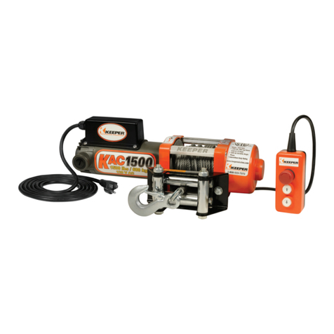
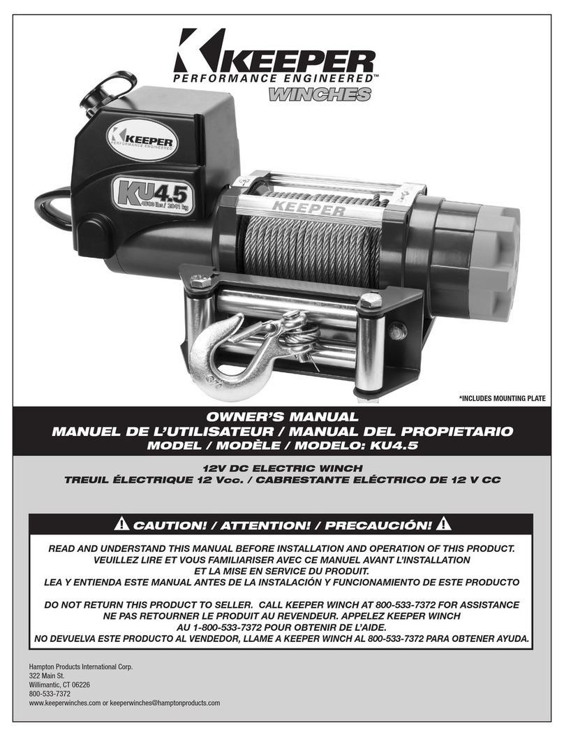
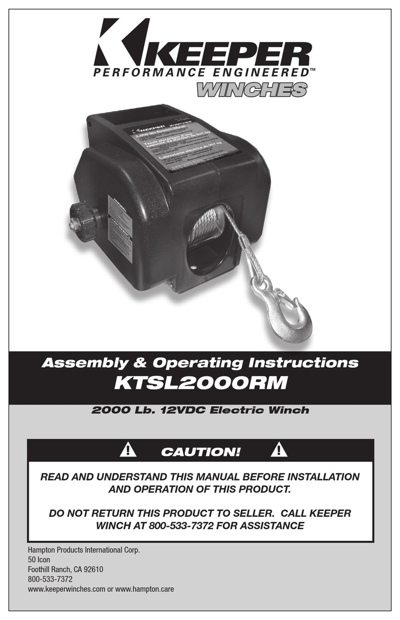
Keeper KX9.5 Quick reference guide

Assembly & Operating Instructions
KX9.5 & KX9.5S
9,500 lbs 12V DC Electric Winch
50 Icon, Foothill Ranch, CA 92610
www.keeperwinches.com • www.keeperproducts.com
1-800-533-7372
©2018 Hampton Products International Corporation
CAUTION!
READ AND UNDERSTAND THIS MANUAL BEFORE INSTALLATION
AND OPERATION OF THIS PRODUCT.
DO NOT RETURN THIS PRODUCT TO SELLER. CALL
KEEPER WINCH AT 800-533-7372 FOR ASSISTANCE
! !
999-09024_KX9500-KX9500S_OM_REVA
*Mounting plate not included.
WINCHESWINCHESWINCHESWINCHESWINCHESWINCHES
1

KX9.5 & KX9.5S 9500 lb 12V DC Electric Winch
PLEASE READ ALL SAFETY PRECAUTIONS AND WARNINGS BEFORE
INSTALLING AND USING THE WINCH! IF YOU HAVE QUESTIONS PLEASE
CALL 1 800-533-7372
THIS PRODUCT IS NOT INTENDED FOR LIFTING / HOISTING
! !
WARNING
Thank you for purchasing your KEEPER®Winch.
PLEASE READ ALL INSTRUCTIONS, PAYING SPECIAL ATTENTION TO THE
SAFETY INSTRUCTIONS.
Your KEEPER®Winch has been designed and manufactured to provide years of trouble-free operation.
If you are not satised, for any reason, please contact Customer Service at 800-533-7372, visit our website:
in regard to this winch, please give the following information:
Winch Part #____________________ and Serial number___________________________________.
(Please write down this information here for future reference.) (Found on Motor Housing)
Please read and understand this Owner’s Manual prior to installing and operating this product.
PAY PARTICULAR ATTENTION TO THE GENERAL SAFETY INFORMATION.
Your Winch is a powerful machine. If used unsafely or improperly, there is a possibility that property damage
and/or personal injury can result. Your safety ultimately depends on your caution when using this product.
The Danger, Warnings, Cautions, and Instructions discussed in this instruction manual cannot cover all pos-
sible conditions and situations that may occur. It must be understood by the operator that common sense
and caution are factors which cannot be built into this product, but must be supplied by the operator.
Indicates an imminently hazardous situation which, if not avoided, will result
in death or serious injury.
Indicates a potentially hazardous situation which, if not avoided, could result
in death or serious injury.
Indicates a potentially hazardous situation which, if not avoided, may result
in minor or moderate injury. This notation is also used to alert against unsafe
practices.
Note: Indicates additional information in the installation and operation procedures of your winch.
! !
DANGER
! !
CAUTION
Safety Precautions
Designed for Utility Recovery, and General Utility Winching Applications.
THIS PRODUCT IS NOT INTENDED FOR LIFTING/HOISTING
! !
CAUTION
Introduction
This manual will cover both KX9500 (KX9.5) wire rope and KX9500S (KX9.5S) synthetic rope models
2

You will need this manual for the safety warnings and cautions, assembly instructions, operating proce-
dures, maintenance procedures, trouble shooting, parts list, and diagram. Keep your invoice with this
manual. Write the invoice number on the inside of the front cover. Keep both this manual and your invoice
in a safe, dry place for future reference.
Winch Dimensions and Mounting Bolt Pattern
KX9.5 & KX9.5S SPECIFICATIONS
Part Number:
Rated Line Pull:
Motor - Series Wound:
Control:
Switching:
Gear Train:
Gear Reduction:
Clutch (Freespooling):
Brake:
Wire Rope:
Drum Diameter/Length:
Fairleads:
Battery Leads:
Battery:
Application:
Finish:
Weight:
Warranty:
KX95122B-1 (Wire Rope) & KX95172B-1 (Synthetic Rope)
9,500 lbs., 4,309 kg.
5.5HP 12V DC
Wireless Remote with internal module, Hand Held Remote on 15’ lead with built in High
Density Light.
High Duty Cycle Sealed Solenoid Pack
High Efciency 3-Stage Planetary Gear Set
218:1
Lift and Turn
Mechanical Automatic Cam Activated
100’ of 21/64th Diameter Galvanized Wire Rope with looped thimble, HD Latched Clevis
Hook and Red Warning Area. (KX9.5)
85’ of 3/8” Diameter Synthetic Rope with looped
thimble, HD Clevis Hook and 3’ (1 m) Protective Sleeve on Drum and Clevis End. (KX9.5S)
Diameter 2.5” (63.5 mm) / Length 8.8” (224 mm)
4-Way Roller Fairlead (KX9.5)
Aluminum Hawse Fairlead (KX9.5S)
2 Gauge, 72” (1.83 m)
Minimum 650 CCA
General Utility Load Recovery/Trailer, Truck, Tractor, Equipment
All-Weather Textured Finish
95 lbs. / 43 kg.
Limited Lifetime
Save this Manual
FIGURE 1
THIS PRODUCT IS NOT INTENDED FOR LIFTING / HOISTING
MOUNTING BOLT PATTERN
10” (254mm) x 4.5” (114mm)
6.25"
4.50"
10.00"
4-M10
8.75"
7.25"
21.25"
9.75"
3

This KEEPER® Winch is equipped with a series wound, 12 Volt DC motor and is designed for
INTERMITTENT GENERAL DUTY USE. This electric winch is similar to most electric motor driven tools and
should not be allowed to become overly hot. Stop winch if motor starts to labor or end of motor becomes
hot to the touch. Stop winching and allow motor to cool down. Minimum electrical requirements are 60 amp
alternator and battery with 650 CCA (cold cranking amp) capacity. This Winch (FIGURE 2) is not intended
for use in lifting/hoisting applications and the manufacturer does not warrant it to be suitable for such use.
The Freespool Clutch disengages the gearbox to allow the wire or synthetic rope to be pulled out without
using electric power. A Remote Switch with 15’ lead and wireless switch allows a wide variety of mounting
options.
General Description
SLOPE* 10% (5.7º) 20% (9º) 40% (18º) 60% (27º) 100% (45º)
Rolling Load Capacities (1st Layer)
*SLOPE: a one (1') rise over ten (10') feet in length equals a GRADE of 10%. A 10% grade is equal to a 5.71º incline
angle. A 100% grade equals a 45º angle of incline.
FIGURE 2
Wireless Switches (2) 15’ Handheld Switch
Battery Leads
4-Way
Roller Fairlead
(KX9.5)
Lbs. 48,450 32,400 20,900 16,150 13,600
Kgs. 22,980 14,700 9,480 7,320 6,170
*MOUNTING PLATE NOT INCLUDED
Aluminum
Hawse Fairlead
(KX9.5S)
KX9.5 Shown
*BATTERY NOT INCLUDED
Line Pull Lbs. (kg) Line Speed FPM (MPM) Motor Amp Dr Pull By Layer Lbs. (kg)
0 28.3 (8.6) 80 1 @ 9500 (4310)
2000 ( 907) 16.6 (5.1) 160 2 @ 8075 (3662)
4000 (1814) 12.2 (3.7) 220 3 @ 6864 (3113)
6000 (2722) 9.8 (3.0) 260 4 @ 5834 (2646)
8000 (3629) 8.1 (2.5) 310
9500 (4310) 4.2 (1.3) 360
12V DC PERFORMANCE
4

Rolling Load Capacities (1st Layer)
*SLOPE: a one (1') rise over ten (10') feet in length equals a GRADE of 10%. A 10% grade is equal to a 5.71º incline
angle. A 100% grade equals a 45º angle of incline.
Double Line Single Line
FIGURE 3
1. READ AND UNDERSTAND THIS MANUAL BEFORE OPERATING YOUR WINCH. After installing the Winch,
practice using it before the need arises. NEVER ALLOW PERSONS UNFAMILIAR WITH THIS PRODUCT
TO OPERATE IT. ALWAYS WEAR SAFETY GLASSES AND LEATHER GLOVES WHILE WORKING WITH
MACHINERY.
2. DO NOT EXCEED RATED CAPACITY OF
THE WINCH. DO NOT OVERLOAD! DO NOT
ATTEMPT PROLONGED PULLS OF HEAVY
LOADS! Overloads can damage the Winch
and/or the wire rope and create unsafe
operating conditions. FOR LOADS OVER
75% OF THE RATED WINCH CAPACITY,
WE RECOMMEND THE USE OF A PULLEY
BLOCK TO DOUBLE LINE THE WIRE ROPE .
(Figure 3). This reduces the load on the Winch, the strain on the rope and electrical system.
3. Never apply a load to your winch with the wire or synthetic rope fully extended. Keep at least 5 wraps on
the
winch drum.
4. THE VEHICLE ENGINE SHOULD BE RUNNING DURING WINCH OPERATION. If winching is performed with
the engine turned off, the battery may be too weak to restart the engine.
5. DO NOT operate your vehicle to assist the Winch in pulling the load. The combination of the Winch and
vehicle pulling together could overload the wire or synthetic rope and the Winch.
6. WHEN IN USE, ALWAYS STAND CLEAR OF WIRE ROPE, HOOK
AND WINCH.
7A. INSPECT WIRE ROPE AND EQUIPMENT FREQUENTLY. A
FRAYED, KINKED OR FLATTENED WIRE ROPE NEEDS TO BE
REPLACED IMMEDIATELY. Periodically check the Winch installa-
tion to ensure that all bolts are tight.
7B. INSPECT SYNTHETIC ROPE AND EQUIPMENT FREQUENTLY.
A FRAYED, KINKED, OR MELTED SYNTHETIC ROPE NEEDS
TO BE REPLACED IMMEDIATELY. Periodically check the winch
instillation to ensure that all bolts are tight and secure.
Tree
Saver
FIGURE 5
General Safety Warnings & Cautions
! !
Lbs. 48,450 32,400 20,900 16,150 13,600
Kgs. 22,980 14,700 9,480 7,320 6,170
Aluminum
Hawse Fairlead
(KX9.5S)
8. USE HEAVY LEATHER GLOVES when handling rope. DO NOT
LET ROPE SLIDE THROUGH YOUR GLOVED OR UNGLOVED
HANDS. ALWAYS USE THE HAND-SAVER STRAP when guiding the rope in or out (Figure 4).
9. NEVER WINCH WITH LESS THAN 5 WRAPS OF ROPE AROUND THE WINCH DRUM since the wire rope
end fastener may NOT withstand full load.
10.KEEP CLEAR OF WINCH, TAUT ROPE AND HOOK WHEN OPERATING WINCH. NEVER STEP OVER TAUT
ROPE.
11. NEVER HOOK THE ROPE BACK ONTO ITSELF. This will damage the rope. Use a KEEPER 02953 3” X 6’
WINCH STRAP, tree saver or other recommended accessory for this type
connection (Figure 5).
12. NEVER USE YOUR WINCH FOR LIFTING OR
MOVING PEOPLE!
13. YOUR WINCH IS NOT INTENDED FOR OVER
HEAD HOISTING OPERATIONS.
14. AVOID CONTINUOUS PULLS FROM
EXTREME ANGLES. This will cause the rope to
pile and jam in the Winch, causing damage to
the rope or Winch (Figure 6).
FIGURE 4
Line Pull Lbs. (kg) Line Speed FPM (MPM) Motor Amp Dr Pull By Layer Lbs. (kg)
5

THIS PRODUCT IS NOT INTENDED FOR LIFTING / HOISTING
FIGURE 6
General Safety Warnings & Cautions (Continued)
15. NEVER OBSCURE THE WARNING INSTRUCTION
LABELS ON THE WINCH.
16. It is highly recommended to lay a heavy cloth
(such as a blanket or tarp) over the wire rope
when pulling heavy loads (Figure 7). If a wire
rope failure should occur, the cloth will act as a
damper and help prevent the wire rope from
whipping. If mounted on the front of a vehicle
then raise the hood for further protection.
17. Always operate Winch with an unobstructed
view of the Winching operation.
18. Equipment such as hooks, pulley blocks,
straps,etc. should be sized for winch
capacity and periodically inspected for
damage that could reduce their strength.
19. NEVER RELEASE FREESPOOL CLUTCH
WHEN THERE IS A LOAD ON THE WINCH.
20. NEVER WORK ON OR AROUND THE WINCH
DRUM WHEN WINCH OR ROPE IS UNDER LOAD.
21. DO NOT OPERATE WINCH WHEN UNDER THE INFLUENCE OF ANY DRUGS OR ALCOHOL.
22. ALWAYS DISCONNECT WINCH POWER LEADS TO BATTERY BEFORE WORKING ON OR AROUND THE
WINCH DRUM so that Winch cannot be turned on accidentally.
23. When moving a load, slowly take up rope slack until it is taut. Stop, recheck all Winching connections.
Be sure the hook is properly seated. If a tree saver is used, check the attachment to the load.
24. When using a vehicle mounted Winch to move a load, place the vehicle transmission in neutral (never in
Park), set vehicle hand-brake, and chock all wheels.
25. DO NOT USE THE WINCH TO HOLD LOADS IN PLACE. Use other means of securing loads such as
KEEPER brand tie-down straps. For tie-down information go to www.keepercorp.com
26. USE ONLY FACTORY APPROVED SWITCHES, ADAPTERS, REMOTE CONTROLS AND ACCESSORIES.
Use of non-factory approved components may cause injury or property damage and could void your
warranty.
27. DO NOT MACHINE OR WELD ANY PART OF THE WINCH. Such alteration may weaken the structural
integrity of the Winch and could void your warranty.
28. This is a 12 Volt DC Winch. CONNECT ONLY TO 12 VOLT DC BATTERY. DO NOT CONNECT WINCH TO
EITHER 110V OR 220V AC CURRENT AS WINCH WILL BURN OUT OR FATAL SHOCK WILL OCCUR.
This will void warranty.
29. Never allow shock loads to be applied to Winch or rope.
30. USE EXTREME CAUTION WHEN WINCHING A LOAD UP AND DOWN A RAMP OR INCLINE.
31. Keep people, pets, and property clear of Winching path, front, rear and sides for 80’.
32. NEVER EXCEED RATING OF YOUR RECIEVER HITCH.
FIGURE 7
Tree
Saver
! !
6

THIS PRODUCT IS NOT INTENDED FOR LIFTING / HOISTING
Winch Installation
Correct installation of your Winch is required for proper operation. Installation should be on a at surface
following the bolt pattern shown in
FIGURE
1.
Read and follow directions carefully to ensure proper Winch alignment and trouble free operation.
This Winch MUST be mounted with the rope in the under-wind direction (
FIGURE
8).
MUST use only genuine Keeper Winch replacement Wire Rope part number KWA14520 or Synthetic Rope part
number KVA10041S.
! !
WARNING
Improper mounting could damage your Winch
and void your warranty.
Step 1 Mount the Winch to the mounting kit base plate, proper
mounting bolts are supplied. If using the Roller
Fairlead or Hawse Fairlead included, install now to mounting plate. You may need to remove one or more of
the rollers on the roller fairlead to pass through the wire rope. After doing this you may now attach the clevis
hook. See
(Figure 8)
for order and bolt direction.
! !
WARNING
DO NOT EXCEED THE RATING OF YOUR RECIEVER HITCH
Mounting Plate
4-Way
Roller Fairlead
Wire Rope or Synthetic Rope
Under-wind Direction
Does not include Mounting Plate (KWA14622)
FIGURE 8
Aluminum Hawse
Fairlead
7

Black 2GA
Negative
Battery Lead
Black 14 GA
Ground Lead
Circuit Breaker
Red 2GA Positive
Battery Terminal
Lead
WARNING
USE ONLY 3/8” -16 UNC BOLT AND NUTS WITH MINIMUM ISO GRADE 8.8.
WARNING
Batteries contain gases, which are ammable and explosive. WEAR EYE PROTECTION DURING INSTALLA-
TION AND REMOVE ALL METAL JEWELRY. Do not lean over battery while making connections.
WARNING
Ensure that the wiring harness does not interfere or come in contact with any hot or moving engine, suspension,
steering, braking or exhaust parts.
MINIMUM ELECTRICAL REQUIREMENTS ARE 60 AMP ALTENATOR AND BATTERY WITH 650 CCA
(COLD CRANKING AMP) CAPACITY.
!
!
!
!
!
!
Step 3 Connect Black 2 GA battery lead to the negative motor terminal located on the bottom of the motor
and also connect the Black 14 GA ground lead from the solenoid pack to the same negative motor
terminal.
Step 4 Connect the other terminal end of the Black 2 GA battery lead to the negative battery terminal.
If longer wiring harness is required then purchase KWA14607
Step 5 Remove the dust cover on the plug receptacle and insert the plug end of the handheld pendant
switch. The plug end is keyed and will t easily onto the socket only one way. DO NOT FORCE.
Step 6 Lift and turn the freespool clutch handle to the Disengage position (See
FIGURE
12). Pull 5 feet of
rope off the drum. Return the freespool clutch handle back to Engaged position. Activate the Winch
cable in and out by momentarily pressing the handheld pendant switch to check drum rotation
direction. The switch is labeled “IN” for winching in and “OUT” for winching out. When released
the switch will automatically go to the off position. IF THIS DOES NOT OCCUR THEN REMOVE THE
HAND HELD PLUG FROM THE RECEPTACLE.
If the drum rotates in the wrong direction then check the trouble shooting area in this manual or call
Step 7 You are now ready to winch. Practice winching operations by freespooling cable out and winching in
under low loads. Make sure all wraps are wound on tight and close against the previous wrap. Plan
some tests in advance and learn to watch and listen. Recognize the sound of a light steady pull, a
heavy pull and sounds caused by load jerking or shifting. You will gain condence. ALWAYS WEAR
SAFETY GLASSES, LEATHER GLOVES AND USE THE HAND SAVER STRAP (
FIGURE
4).
Step 2 Follow electrical connection
diagram (
FIGURE
9). Bolt the
circuit breaker to the terminal end
of the Red 2 GA battery lead that
is factory connected to the sealed
solenoid switching pack. Now
connect the circuit breaker to the
positive battery terminal.
Winch Installation (Continued)
FIGURE 9
8

Black 14 GA
Ground Lead
The handheld pendant switch activates a solenoid
that activates power to the winch motor.
To connect the handheld pendant switch, remove
the cover on the plug receptacle and insert the plug
end of remote switch (See Figure 10). The plug on
the pendant control cord is keyed and will t into the
socket only one way.
The switch trigger returns to the “Off” position when
released. To change direction, move the toggle in the
other direction. (See Figure 10).
The red push button activates the LED work light.
The
! !
CAUTION
The switch assembly must be kept free of dirt and
moisture to ensure safe operation.
Pendant Operation
Wireless Operation (Remote KTA14126)
Your winch has an internal Wireless Remote Module that is activated by depressing the switch located on the
side of the top cover to the “up” position. Your Wireless Module is now active and ready for use. To activate
your Wireless Remote Fob, place the switch on your winch to the “On” position. Then depress both buttons
on the Fob at the same time and hold for 3-5 seconds, you will see the indicator light come on. Your Wireless
Remote is now active and ready for use. Please note that the unit is programmed for a 1 second delay in both
starting and stopping.
This may represent a 6” to 8” travel in the rope.
Your wireless remote is now ready. Enjoy your wireless remote switch winching experience.
FIGURE 10 IN OUT
FIGURE 11
Wire
Rope
OUT
Wire
Rope
IN
Key
Slot
Key
Slot
ON
OFF
Indicator
Light
9

10
FIG. 1
©2018 Hampton Products International Corp.
50 Icon, Foothill Ranch, CA 92610
800-533-7372
www.hamptonproducts.com
www.keeperwinches.com
Reprogramming Instructions for Wireless Remote
WINCHESWINCHESWINCHESWINCHESWINCHESWINCHES
1) To begin you will need to remove the screws on the top of your unit to expose
the internal control module.
2) You must have power to your winch during this process, take extra caution to
ensure body parts or clothing is clear of the winch in case the unit activates.
3) Inside the top cover you will nd the circuit board and wireless receiver. (Fig 1.)
4) Using a metal tweezer or copper jump wire, contact the two small holes on the
receiver while pressing either button on your new wireless remote. (Fig 2.)
5) Hold for 3 seconds, you should hear a “tone” conrming the winch and wireless
remote are now in sync.
6) If you do not hear a “tone”, please repeat steps 4 & 5 making sure your jump
wire is in contact with the metal contact points on the receiver.
7) Replace cover, ensure that no wires are pinched or cut during this process.
8) Retest your unit to conrm both In/Out operations function properly.
9) If you are unable to successfully sync the winch and wireless remote, please
contact our Customer Service at 1-800-533-7372 for personal assistance.
In the event you need to replace your Wireless Remote (due to loss or damage) you can replace it with Keeper # KTA14126 Wireless Remote Switch.
Your KX Model has an internal wireless control module that will need to be accessed to accomplish this. If you have questions or concerns about
accomplishing this, please call our Customer Service at 1-800-533-7372 8:00 – 4:00 PM EST and ask for a winch technician, we will be happy to walk
you through the necessary steps.
En cas de remplacement de la télécommande sans l (en cas de perte ou de casse), elle peut être remplacée par la télécommande sans l Keeper
KTA14126.
Le modèle KX dispose d'un module de contrôle sans l interne auquel il faut accéder pour accomplir cette tâche. En cas de questions ou de doutes sur
cette opération, merci d'appeler le service clientèle au 1-800-533-7372 8:00 - 16:00 EST et demander un technicien de treuil qui sera heureux de
fournir toute l'aide nécessaire tout au long des étapes.
En el caso de que necesite reemplazar su control remoto (por pérdida o daños), puede hacerlo con el interruptor remoto inalámbrico Keeper #
KTA14126.
Su modelo KX tiene un módulo de control inalámbrico interno al que deberá acceder para realizar la reprogramación. Si tiene preguntas o consultas
sobre el proceso, llame a nuestro Centro de atención al cliente al 1-800-533-7372 de 8:00 a 4:00 p.m. EST y solicite hablar con un técnico de
cabrestante y con gusto lo ayudaremos en todos los pasos necesarios.
Instructions de reprogrammation de la télécommande sans l
Instrucciones de reprogramación para control remoto inalámbrico
FIG. 2
1) Commencer par retirer les vis situées sur le dessus de l'appareil pour exposer
le module de contrôle interne.
2) Il faut alimenter le treuil pendant ce processus, prendre de grandes précautions
pour s'assurer que les parties du corps ou les vêtements sont dégagés du treuil au
cas où l'appareil serait mis en fonction.
3) À l'intérieur du capot supérieur, se trouve le circuit imprimé et récepteur sans
l. (Fig. 1)
4) À l'aide d'une pince métallique ou d'un l de cuivre, faire un contact entre les
deux petits trous du récepteur tout en appuyant sur l'un des boutons de la
nouvelle télécommande sans l. (Fig. 2)
5) Maintenir la touche enfoncée pendant 3 secondes, une « tonalité » se fait
entendre conrmant que le treuil et la télécommande sans l sont maintenant
synchronisés.
6) S'il n'y a pas de « tonalité », répéter les étapes 4 et 5, en s'assurant que le l
est bien en contact avec les deux points de contact sur le récepteur.
7) Remettre le couvercle en place, en veillant à ce qu'aucun l ne soit pincé ou
coupé pendant l'opération.
1) Para comenzar, necesitará quitar los tornillos de la parte superior de la unidad para exponer el módulo de control interno.
2) Durante este proceso es necesario que el cabrestante reciba energía eléctrica. Tome precauciones adicionales para asegurarse de que su cuerpo
y ropa no estén en contacto con el cabrestante en caso de que se active la unidad.
3) Dentro de la cubierta superior encontrará la placa de circuitos y el receptor inalámbrico. (Fig. 1)
4) Con una pinza de metal o un cable conector de cobre, contacte los dos pequeños oricios en el receptor y presione algún botón del nuevo control
remoto inalámbrico. (Fig. 2)
5) Mantenga presionado por 3 segundos hasta escuchar un “tono” que conrmará que el cabrestante y el control remoto inalámbrico están
sincronizados.
6) Si no escucha un “tono”, repita los pasos 4 y 5 y asegúrese de que el cable conector esté en contacto con los puntos de contacto metálicos del
receptor.
7) Reemplace la cubierta y asegúrese de no apretar o cortar ningún cable durante este proceso.
8) Vuelva a probar la unidad para conrmar que las operaciones de entrada/salida funcionan correctamente.
9) Si no puede sincronizar correctamente el cabrestante y el control remoto inalámbrico, contáctese con el Servicio de atención al cliente al
1-800-533-7372 para obtener ayuda personal.
8) Retester l'appareil pour conrmer que les opérations de rembobinage et de dévidage fonctionnent toutes les deux correctement.
9) Au cas où la synchronisation du treuil et de la télécommande sans l ne se fait pas, contacter notre service à la clientèle au 1-800-533-7372
pour obtenir de l'aide.

Extending the Life of Your Winch
Your winch incorporates an automatic load holding
brake. After winching in a load, this mechanism
holds the load, up to the rated capacity of the winch.
While powering out the load, the winch controls the
rate of speed by applying the brake in proportion
to the amount of the load in the winch cable. This
results in heavier loads powering-out more slowly
than lighter loads.
Similar to the friction-type brakes in your automobile
which can generate heat if used for a long period of
time, the winch brake can generate heat if used to
power-out a load for a long period of time.
Brake Operation
To ensure optimimum winch performance, al-
ways limit powering-out a load to 2 minutes and
allow the brake to cool for 15 minutes
before continuing to winch.
Under normal use, the brake mechanism should not
require any adjustment. Should the brake fail to hold
a load or maintain a constant rate of speed during
power-out operation, the brake spring may be worn
and require replacement.
FOR PARTS INFORMATION PLEASE CHECK www.keeperwinches.com,
Freespool Operation
1. Lift and rotate the clutch lever to the “Disengaged”
position as shown in Figure 12. If there is a load on
the rope, the clutch lever may not turn easily. DO
NOT FORCE THE CLUTCH LEVER. Release tension
by jogging out some of the rope, then try releasing
the clutch.
2. Pull out the rope and secure to anchor or load.
3. Check that there are at least ve (5) wraps of
rope left on the drum.
4. Re-engage the drum by lift and rotating the
clutch lever to the “Engaged” position, apply
power to engage clutch (see Figure 12).
FIGURE 12
ENGAGE
DISENGAGE
! !
CAUTION
Lever must be in the engaged position and
locked before winching.
The following guidelines apply for both wire rope and synthetic rope models
1. KEEP A TIGHTLY WOUND WIRE ROPE DRUM. Keep the wire rope tightly and evenly wound on the drum all
the time. Do not allow the wire rope to become loosely wound. A loosely wound drum allows a wire rope
under load to work its way down into the layers of wire rope on the drum. When this happens, the wire
rope may become wedged within the body of the windings damaging the wire rope. A good practice is to
rewind the wire rope under tension after each use. Apply tension using hand saver strap (
FIGURE
3) and
ALWAYS wear safety glasses and leather gloves.
2. DO NOT ALLOW WINCH MOTOR TO OVERHEAT. Keep the duration of pulls as short as possible. If the
motor becomes uncomfortably hot by touching, stop winching and allow the motor to cool down.
KEEP THE VEHICLE ENGINE RUNNING TO RECHARGE THE BATTERY during the cooling break.
11

3. USE A PULLEY BLOCK FOR HEAVY LOADS. To maximize Winch and rope life, use a pulley block (not
included) to double line heavier loads. (See
FIGURE
3) For maximum performance use a pulley block that
is greater than 75% of the rated capacity of the winch. For the 9,500 lbs. winch use a pulley block once
you exceed 7,125 lbs. Always use a pulley block (for part number Call Keeper Winch) that is rated twice
the capacity of the winch.
CAUTION
If the winch motor stalls, do not continue to apply power.
4. The pull required to start a load moving is often much greater than the pull required to keep it moving.
AVOID FREQUENT STOPS AND STARTS DURING THE PULL.
5. PREVENT KINKS IN WIRE ROPE BEFORE THEY OCCUR
(
FIGURE
13).
a. This is the start of a kink. Wire rope should be straight-
ened.
b. Wire rope was pulled and loop has tightened into a kink.
Wire rope is now permanently damaged and MUST be
replaced.
c. Result of kinking is that each strand pulls a different amount causing strands under greatest tension
to break and reduce load capacity of wire rope. The wire rope MUST be replaced. Use only genuine
Keeper Winch replacement part number KWA14520 100’ X 21/64”
to order.
! !
WARNING
WARNING
!
!
!
!
FIGURE 14
Winch Drum
Never Substitute a heavier or lighter wire rope. Never
use rope made of any other materials other than wire.
Use only recommended Keeper replacement wire
rope, 100’ x 21/64” KWA14520.
Attach wire rope to the drum using screw provided
FIGURE
14).
Never substitute a heavier or lighter synthetic rope. Never use rope made of other materials than originally
supplied with your unit. Use only recommended Keeper replacement synthetic rope part number KVA10041S.
Synthetic Rope is an excellent alternative to wire rope providing a weight savings on your vehicle and much
easier to handle. Synthetic Rope can also be much safer in the event of a line break and less susceptible to
backlash during failure. Keeper still recommends using our Winch Safety Blanket part number KWA400All for
all winching activities.
Fraying of the rope is the major concern and can reduce the strength of your synthetic rope considerably. Al-
ways take special care to eliminate running the rope over edges that may promote damage. If a cut or fraying
is discovered, immediately replace the synthetic rope for strength and safety concerns.
Extending the Life of Your Winch
Replacing The Wire Rope
Replacing the Synthetic Rope
FIGURE 13
1) Remove all old and damaged synthetic rope from the drum and inspect to ensure there are no burrs or
sharp edges on the drum. Remove the protective sleeve on the leading and trailing end of the old rope and
Synthetic Rope Care and Replacement
12

The following guidelines apply for both wire rope and synthetic rope models
1. KEEP A TIGHTLY WOUND WIRE ROPE DRUM. Keep the rope tightly and evenly wound on the drum all the
time. Do not allow the rope to become loosely wound. A loosely wound drum allows a rope under load to
work its way down into the layers of rope on the drum. When this happens, the rope may become wedged
within the body of the windings damaging the wire rope. A good practice is to rewind the rope under ten-
sion after each use. Apply tension using hand saver strap (
FIGURE
3) and ALWAYS wear safety glasses and
leather gloves.
2. DO NOT ALLOW WINCH MOTOR TO OVERHEAT. Keep the duration of pulls as short as possible. If the
motor becomes uncomfortably hot by touching, stop winching and allow the motor to cool down.
KEEP THE VEHICLE ENGINE RUNNING TO RECHARGE THE BATTERY during the cooling break.
3. USE A PULLEY BLOCK FOR HEAVY LOADS. To maximize Winch and rope life, use a pulley block (not
included) to double line heavier loads. (See
FIGURE
3) For maximum performance use a pulley block that
is greater than 75% of the rated capacity of the winch. For the 9,500 lbs. winch use a pulley block once
you exceed 7,125 lbs. Always use a pulley block (for part number Call Keeper Winch) that is rated twice
the capacity of the winch.
CAUTION
If the winch motor stalls, do not continue to apply power.
4. The pull required to start a load moving is often much greater than the pull required to keep it moving.
AVOID FREQUENT STOPS AND STARTS DURING THE PULL.
5. PREVENT KINKS IN ROPE BEFORE THEY OCCUR (
FIGURE
13).
a. This is the start of a kink. Rope should be straightened.
b. Rope was pulled and loop has tightened into a kink. Rope is now permanently damaged and MUST be
replaced.
c. Result of kinking is that each strand pulls a different amount causing strands under greatest tension to
break and reduce load capacity of rope. The rope MUST be replaced. Use only genuine Keeper Winch
replacement part number KWA14520 100’ X 21/64”
Before each use, check mounting bolts for tightness, inspect rope for damage. Inspect remote control
assembly for any damage. Periodically use a clean, dry towel to remove dirt and debris from winch housing.
Lubrication: The gear box is permanently lubricated. Do not attempt to disassemble the gear box. This will
void your warranty.
Maintenance & Repair
! !
WARNING
install on the new replacement rope. This provides abrasion and heat protection from damaging the synthetic
rope.
2) Conrm that the length of the replacement rope matches the original length supplied with your unit. You
may need to trim it to the correct length.
3) Feed the trailing end of the rope through the hole in the drum and secure with the set screw. You may
want to wrap the trailing end in tape to make inserting it in the hole easier.
4) Run the new rope with the protective sleeve along the length of the drum and begin winding it on the
drum, making sure it feeds along the bottom. You can use a piece of tape to help hold the sleeved section in
place while winding the rst layer in place.
5) Make sure each layer is installed in an even and tight pattern until the full length is installed. Overlapping
layers can cause difculties in free spooling and up take when you need your winch the most.
13

THIS PRODUCT IS NOT INTENDED FOR LIFTING / HOISTING
Symptom Possible Causes Corrective Action
Motor will not operate
or runs in one direc-
tion only
Motor runs extremely
hot
Motor runs but with
insufficient power or
line speed
Motor runs but drum
does not turn
Winch runs backwards
1. Broken wires or bad battery
connection
2. Switch inoperative
3. Damaged winch
4. Damaged solenoid
5. Circuit breaker malfunction
1. Long period of operation
2. Damaged during operation
1. Weak/Low battery
2. Battery to Winch wire too long
3. Poor battery connection
4. Poor ground
5. Damaged motor
Clutch not engaged
1. Battery wires reversed
2. Switch wires reversed
3. Switch installed incorrectly
1. Check for poor connection(s) and that
all wiring is tight and clean
2. Check that switch wires are connected
properly to the solenoid
3. Replace or repair
4. Replace solenoid
5. Replace circuit breaker
1. Allow to cool
2. Replace or repair
1. Recharge or replace battery. Check
charging system.
2. Use only supplied wires. If increase in
length is needed, drop down wire size
to 2 or 3 AWG.
3. Check battery terminals for corrosion.
Clean as required.
4. Check and clean connections
5. Replace or repair
Engage clutch
1. Recheck wiring
2. Recheck wiring
3. Check switch installation
LIMITED WARRANTY: Hampton Products International Corporation Warrants product according to provisions below: Mechanical
components are warranted for lifetime of the winch to be free from defects of material and workmanship. Electrical components
are warranted for 1 year to be free from defects of material or workmanship. If a defect in material or workmanship occurs, call
800-533-7372 for instructions on how to have the Product repaired or replaced. This Warranty applies only to the original Pur-
chaser/Consumer of the Products from the date of purchase of the Product. Defective Products returned become property of the
manufacturer. Limitations on the Warranty:The following limitations apply to the Warranty: (a) The Warranty applies only to Products
which are defective in material or workmanship. This Warranty does not cover normal wear and tear. The Warranty does not cover
service or labor charges which are incurred in removing or replacing any Product. (b) The Warranty does not cover the winch nish
or wire rope. Accordingly, the manufacturer will not replace, repair or renish any Products if the nish on the Product is worn in
any manner. (c) The Warranty does not extend to Products which are damaged or which fail as a result of the Product being abused,
neglected, or misused in any manner, or as a result of any accident, or which are misapplied, overloaded, improperly installed, or
altered in any manner by anyone other than the manufacturer its agents or representatives.
Obligations of Purchaser/Consumer. To obtain the benets of the Warranty, The Purchaser/Consumer must return the defective
Product(s), freight prepaid together with proof of purchase within the warranty period from the date of purchase to Hampton Prod-
ucts or an authorized service center.
Legal Rights and Limitations of Purchaser/Consumer. THIS WARRANTY GIVES YOU SPECIFIC LEGAL RIGHTS AND YOU ALSO MAY
HAVE OTHER RIGHTS WHICH VARY FROM STATE TO STATE. ANY IMPLIED WARRANTY OF MERCHANTABILITY OR FITNESS FOR
A PARTICULAR PURPOSE ON ANY PRODUCT SHALL BE LIMITED TO TERMS OF WARRANTY FROM THE DATE OF PURCHASE AT
RETAIL TO THE ORIGINAL PURCHASER. SOME STATES DO NOT ALLOW LIMITATIONS
Hampton Products International Corp.
50 Icon
Foothill Ranch, CA 92610 USA
800-533-7372
If a problem arises, DO NOT RETURN TO RETAILER call Keeper
®
Winch Customer Service at 800-533-7372 or e-mail
Troubleshooting
14

Instructions d’assemblage et d’utilisation
KX9.5 et KX9.5S
Treuil électrique de 4 309 kg (9 500 lb) 12 Vcc
50 Icon, Foothill Ranch, CA 92610
www.keeperwinches.com • www.keeperproducts.com
1-800-533-7372
©2018 Hampton Products International Corporation
ATTENTION!
NE PAS RETOURNER CE PRODUIT AU REVENDEUR.
POUR OBTENIR DE L’ASSISTANCE, CONTACTER LE SER-
VICE À LA CLIENTÈLE KEEPER WINCH AU 800-533-7372
! !
999-09024_KX9500-KX9500S_OM_REVA
*Plaque de xation non incluse
TREUILSTREUILSTREUILS
LIRE ET S’ASSURER DE COMPRENDRE CE MANUEL AVANT
L’INSTALLATION ET L’UTILISATION DE CE PRODUIT.
15

Merci d’avoir acheté un treuil KEEPER®.
PRIÈRE DE LIRE TOUTES LES INSTRUCTIONS EN ACCORDANT UNE AT-
TENTION PARTICULIÈRE AUX CONSIGNES DE SÉCURITÉ.
Le treuil KEEPER® a été conçu et fabriqué pour offrir des années de service sans défaillances.
En cas d’insatisfaction, pour une raison ou pour une autre, prière de contacter le service à la clientèle au
800-533-7372, ou de visiter le site Web : www.keeperwinches.com ou de contacter winches@hampton-
products.com. Lors d’une demande d’information concernant le treuil, merci de fournir les renseignements
suivants :
Référence produit du treuil ____________________ et numéro de série ________________________
___________.
(Prière d’inscrire ces renseignements ici pour référence future.) (Peuvent être trouvés sur capot moteur)
Prière de lire et s’assurer de comprendre ce manuel d’utilisation avant d’installer et d’utiliser le produit.
PORTER UNE ATTENTION PARTICULIÈRE AUX INFORMATIONS GÉNÉRALES SUR LA SÉCURITÉ.
Ce treuil est une machine puissante. Une mauvaise utilisation ou une utilisation non sécuritaire peut en-
traîner des dommages aux biens et/ou des blessures. La sécurité dépend de la prudence de l’utilisateur lors
de la manipulation de ce produit.
Les rubriques Danger, Avertissement, Mises en garde et Instructions gurant dans ce manuel d’utilisation ne
peuvent couvrir toutes les situations et circonstances qui peuvent se présenter. L’opérateur doit compren-
dre que le bon sens et la prudence sont des facteurs qui ne peuvent être intégrés au produit, mais dont
l’opérateur doit faire preuve.
! !
ATTENTION
Treuil électrique KW9.5 et KX9.5S 4 309 kg (9 500 lb)
PRIÈRE DE LIRE TOUTES LES INSTRUCTIONS EN ACCORDANT UNE AT-
TENTION PARTICULIÈRE AUX CONSIGNES DE SÉCURITÉ. EN CAS DE
QUESTION, MERCI D’ENVOYER UN MESSAGE À WINCHES@HAMPTON-
PRODUCTS.COM OU D’APPELER AU 1 800-533-7372
CE PRODUIT N’EST PAS CONÇU POUR LE LEVAGE
! !
AVERTISSEMENT
! !
DANGER
! !
MISE EN GARDE
Consignes de sécurité
Conçu pour les utilitaires de récupération et les applications générales de treuillage.
CE PRODUIT N’EST PAS CONÇU POUR LE LEVAGE
Introduction
Ce manuel couvre à la fois le modèle KX9500 (KX9.5) à câble métallique, et le modèle KX9500S
(KX9.5S) à corde synthétique.
Indique un risque imminent de situation dangereuse qui, si elle n’est pas
évitée, entraînera la mort ou de graves blessures.
Indique une situation potentiellement dangereuse qui, si elle n’est
pas évitée, pourrait entraîner la mort ou de graves blessures.
Indique une situation potentiellement dangereuse qui, si elle n’est
pas évitée, peut entraîner une blessure mineure ou modérée. Cette
notation est également utilisée pour mettre en garde contre des
pratiques non sécuritaires.
Remarque : Indique des renseignements supplémentaires concernant les procédures d’installation et de
fonctionnement du treuil.
16

SPÉCIFICATIONS du KX9.5 et du KX9.5S
Numéro de référence :
Force de traction nominale en ligne:
Moteur – excitation en série :
Commande :
Commutation :
Train d’engrenages :
Rapport de réduction :
Débrayage manuel (tambour en roue libre) :
Frein :
Câble en acier :
Diamètre du tambour/longueur :
Guide-câble :
Câbles de batterie :
Batterie :
Application :
Fini :
Poids :
Garantie :
KX95122B-1 (Câble en acier) & KX95172B-1 (Corde synthétique)
4 309 kg (9 500 lbs)
5,6 Ch, 12 Vcc
Télécommande laire avec 5 mètres de câble et lampe-torche haute
densité incorporée.
Solénoïde en boîtier scellé pour un cycle d’utilisation élevé.
Engrenages planétaires à 3 étages haut rendement.
218:1
Poignée à tirer et tourner
Activation mécanique automatique par came
Câble en acier galvanisé de 30,48 m (100 pieds) de long et 8,3 mm
(21/64 po) de diamètre, avec tête en boucle, crochet renforcé à
chape, linguet et zone d’alarme rouge. (KX9.5)Corde synthétique de
25,90 m (85 pieds) de long et 9,5 mm (3/8 po) de diamètre, avec
tête en boucle, crochet renforcé à chape, et une gaine de protection
de 1m (3 pieds) à chaque extrémité. (KX9.5S)
Diamètre – 63,5 mm (2,5 po)/longueur – 224 mm (8,8 po)
Guide-câble à rouleaux 4 directions (KX9.5)
Guide-câble écubier en aluminium (KX9.5S)
Section 33,6 mm² (2 AWG), 1,83 m (72 po)
Courant de démarrage à froid minimal 650 A
Usage général de traction de charge/Remorque, camion, tracteur,
équipement
Finition tout-temps texturée
95 lbs. / 43 kg.
À vie limitée
Ce manuel sera nécessaire pour consulter les avertissements de sécurité et les mises en garde, les instruc-
tions d’assemblage, la procédure d’utilisation, les procédures d’entretien, le guide de dépannage, la liste
des pièces et les schémas. Conserver la facture avec ce manuel. Inscrire le numéro de facture à l’intérieur
de la couverture. Conserver ce manuel ainsi que la facture dans un endroit sec et protégé aux ns de
référence future.
Dimensions du treuil et schéma de pose des boulons de
Conserver ce manuel
FIGURE 1
CE PRODUIT N’EST PAS CONÇU POUR LE LEVAGE
SCHÉMA DE POSE DES
BOULONS DE FIXATION
254 mm (10 po) x 114 mm (4,5 po)
159mm
114mm
254mm
4xM10
222mm
184mm
540mm
248mm
17

Ce treuil KEEPER® est équipé d’un moteur à enroulements série de 12 Vcc et est conçu pour UNE UTILISA-
TION GÉNÉRALE INTERMITTENTE. Ce treuil électrique, tout comme la plupart des outils entraînés par moteur
électrique, ne doit pas surchauffer. Arrêter le treuil si le moteur commence à forcer ou si l’extrémité du mo-
teur devient chaude au toucher. Arrêter de treuiller et laisser refroidir le moteur. Les spécications électriques
minimales sont un alternateur de 60 A et une batterie supportant un ADF (Ampérage de démarrage à froid)
minimal de 650 A. Ce treuil (FIGURE 2) n’est pas prévu pour des applications de levage et le fabricant ne ga-
rantit pas qu’il convienne à cet usage. L’embrayage de décrabotage désaccouple le réducteur pour permettre
de dérouler le câble ou la corde sans utiliser la puissance électrique. Une télécommande laire avec 4,57 m
(15 pi) de l et une télécommande sans l permettent une grande variété d’options de montage.
Description générale
PENTE* 10 % (5,7 o) 20 % (9 o) 40 % (18 o) 60 % (27 o) 100 % (45 o)
Capacité pour une charge roulante
(1re couche d’enroulements)
*PENTE : un dénivelé de 10 m sur une longueur de 100 m équivaut à une PENTE de 10 %. Une pente de 10 % est
égale à un angle d’inclinaison de 5,71°. Une pente de 100 % est égale à un angle d’inclinaison de 45°.
FIGURE 2
Interrupteurs sans
fil (2)
Interrupteur à main de 4,58 m (15 pi)
Câbles de batterie
Guide-câble à rouleaux 4
directions (KX9.5)
Lbs. 48 450 32 400 20 900 16 150 13 600
Kgs. 22 980 14 700 9 480 7 320 6 170
*PLAQUE DE FIXATION NON INCLUSE
Guide-câble écubier
en aluminium (KX9.5S)
KX9.5 illustré
*BATTERIE NON INCLUSE
Force de traction kg (lb)
0 0,14 (0,31) 80 1 @ 4 310 (9 500)
907 (2 000) 0,085 (0,26) 160 2 @ 3 662 (8 075)
1 814 (4 000) 0,062 (0,20) 220 3 @ 3 113 (6 864)
2 722 (6 000) 0,05 (0,16) 260 4 @ 2 646 (5 834)
3 629 (8 000) 0,042 (0,135) 310
4 310 (9 500) 0,022 (0,07) 360
PERFORMANCE 12 VCC
Vitesse de traction m/s (pi/s) Ampérage du moteur Traction par tranche de kg (lb)
18

8. PORTER DES GANTS DE CUIR ÉPAIS pour manipuler le câble. NE PAS LAISSER GLISSER LE CÂBLE
DANS LES MAINS QUE L’ON PORTE DES GANTS OU NON. TOUJOURS UTILISER LA COURROIE
PROTÈGE-MAIN pour guider l’enroulement ou le déroulement du câble (Figure 4).
9. NE JAMAIS TREUILLER AVEC MOINS DE 5 TOURS DE CÂBLE AUTOUR DU TAMBOUR DU TREUIL car
l’attache d’embout du câble pourrait NE PAS résister à la pleine charge.
10. SE TENIR À L’ÉCART DU TREUIL, DU CÂBLE EN TENSION ET DU CROCHET LORSQU’ON UTILISE LE
TREUIL. NE JAMAIS MARCHER SUR LE CÂBLE LORSQU’IL EST TENDU.
11. NE JAMAIS ACCROCHER LE CROCHET SUR LE CÂBLE. Cela pourrait l’endommager. Utiliser une
COURROIE DE TREUIL KEEPER 02953, 7,62 cm x 1,83 m (3 po x 6 pi), une sangle, un protège-arbre ou
tout autre accessoire recommandé pour ce type raccordement (Figure 5).
12. NE JAMAIS UTILISER LE TREUIL POUR
SOULEVER OU DÉPLACER DES PERSONNES !
13. CE TREUIL N’EST PAS CONÇU POUR DES
APPLICATIONS DE LEVAGE.
14. ÉVITER UNE TRACTION CONTINUE AVEC DES
ANGLES EXTRÊMES. Cela causerait un empile-
ment du câble et un blocage dans le treuil,
entraînant des dommages au câble ou au treuil
(Figure 6).
1. LIRE ET S’ASSURER DE COMPRENDRE CE MANUEL AVANT D’UTILISER LE TREUIL. Après avoir installé
le treuil, faire quelques essais avant de l’utiliser. NE JAMAIS LAISSER DES PERSONNES UTILISER CE
PRODUIT SANS Y ÊTRE FAMILIARISÉ. TOUJOURS PORTER DES LUNETTES DE SÉCURITÉ ET DES
GANTS DE CUIR LORSQU’ON UTILISE CETTE MACHINE.
2. NE PAS DÉPASSER LA CAPACITÉ NOMINALE DU TREUIL. NE PAS SURCHARGER ! NE PAS ESSAYER
DE TIRER DE LOURDES CHARGES SUR UNE
LONGUE DISTANCE ! Les surcharges peuvent
endommager le treuil et/ou le câble et créer
des conditions d’utilisation non sécuritaires.
POUR LES CHARGES DÉPASSANT 75 %
DE LA CAPACITÉ NOMINALE DU TREUIL,
NOUS RECOMMANDONS L’UTILISATION
D’UN MOUFLE AFIN DE DOUBLER LE CÂBLE
(Figure 3). Cela permet de réduire la charge
sur le treuil, la tension sur le câble et sur
l’alimentation électrique.
3. Ne jamais appliquer une charge au treuil lorsque le câble est complétement déroulé. Garder au moins 5
tours sur le tambour du treuil.
4. LE MOTEUR DU VÉHICULE DEVRAIT ÊTRE EN MARCHE PENDANT LE FONCTIONNEMENT DU TREUIL.
Si le treuillage est effectué alors que le moteur est arrêté, la batterie pourrait être trop déchargée pour
redémarrer le moteur.
5. NE PAS faire utiliser le véhicule pour aider le treuil à tirer la charge. La combinaison du treuil et du véhi-
cule tirant ensemble pourrait excéder la capacité du câble et du treuil.
6. PENDANT L’UTILISATION DU TREUIL, TOUJOURS SE TENIR
ÉLOIGNÉ DU CÂBLE, DU CROCHET ET DU TREUIL.
7A. INSPECTER FRÉQUEMMENT LE CÂBLE ET L’ÉQUIPEMENT.
UN CÂBLE EFFILOCHÉ, ENTORTILLÉ OU APLATI DOIT ÊTRE
REMPLACÉ IMMÉDIATEMENT. Vérier périodiquement
l’installation du treuil pour s’assurer que tous les boulons sont
bien serrés.
7B. INSPECTER FRÉQUEMMENT LA CORDE SYNTHÉTIQUE ET
L’ÉQUIPEMENT. UNE CORDE EFFILOCHÉE, ENTORTILLÉE OU
FONDUE DOIT ÊTRE REMPLACÉE IMMÉDIATEMENT. Vérier
périodiquement l’installation du treuil pour s’assurer que tous les
boulons sont bien serrés.
Ligne double Ligne simple
FIGURE 3
Sangle
protège-arbre
FIGURE 5
Avertissements généraux de sécurité et mises en garde
! !
Lbs. 48 450 32 400 20 900 16 150 13 600
Kgs. 22 980 14 700 9 480 7 320 6 170
FIGURE 4
Traction par tranche de kg (lb)
19

15. NE JAMAIS MASQUER LES ÉTIQUETTES
D’AVERTISSEMENT SUR LE TREUIL.
16. Il est fortement recommandé d’étendre un
tissu épais (tel qu’une couverture ou une bâche)
par-dessus le câble lors de la traction de charges
lourdes (Figure 7). En cas de rupture du câble,
le tissu servira d’amortisseur et contribuera à
empêcher le câble de fouetter. Si le treuil est monté
à l’avant d’un véhicule, ouvrir le capot offre une
protection supplémentaire.
17. Lorsqu’on utilise le treuil, il faut toujours avoir
une vue non obstruée de l’opération de treuillage.
18. Les équipements tels que les crochets, les
moues, les courroies, etc. devraient toujours être
de dimensions adaptées à la capacité du treuil et
être inspectées périodiquement an de détecter
toute altération qui pourrait en réduire la solidité.
19. NE JAMAIS DÉBRAYER LORSQU’IL Y A UNE
CHARGE SUR LE TREUIL.
20. NE JAMAIS TRAVAILLER SUR LE TAMBOUR
DU TREUIL OU AUX ALENTOURS LORSQUE LE
CÂBLE DU TREUIL EST SOUS TENSION.
21. NE PAS FAIRE FONCTIONNER LE TREUIL SOUS INFLUENCE DE MÉDICAMENTS OU D’ALCOOL.
22. TOUJOURS DÉBRANCHER LES FILS D’ALIMENTATION DU TREUIL DE LA BATTERIE AVANT DE
TRAVAILLER SUR LE TAMBOUR DU TREUIL OU AUX ALENTOURS de sorte que le treuil ne puisse être
actionné accidentellement.
23. Lors du déplacement d’une charge, enrouler lentement le surplus de câble jusqu’à ce qu’il soit tendu.
Arrêter, revérier toutes les attaches de treuillage. S’assurer que le crochet est bien en place. Si l’on
utilise une sangle en nylon, vérier la xation à la charge.
24. Lors de l’utilisation d’un treuil monté sur un véhicule pour déplacer une charge, placer la transmission
du véhicule au neutre (jamais en position de stationnement), enclencher le frein à main du véhicule et
caler toutes les roues.
25. NE PAS UTILISER LE TREUIL POUR MAINTENIR DES CHARGES EN PLACE. Utiliser d’autres moyens
pour attacher les charges tels que les sangles d’arrimage de marque KEEPER. Pour des renseignements
sur les sangles d’arrimage, consulter www.keepercorp.com.
26. UTILISER UNIQUEMENT DES INTERRUPTEURS, ADAPTATEURS, COMMANDES À DISTANCE ET AC-
CESSOIRES D’ORIGINE. L’utilisation de composants tiers peut entraîner des blessures ou des dom-
mages aux biens et pourrait annuler la garantie.
27. NE PAS USINER ET NE PAS SOUDER DES PIÈCES DU TREUIL. Une telle altération peut affaiblir
l’intégrité structurelle du treuil et pourrait annuler la garantie.
28. Ceci est un treuil de 12 Vcc. LE RACCORDER UNIQUEMENT À UNE BATTERIE DE 12 VCC. NE PAS RAC-
CORDER LE TREUIL À DU COURANT ALTERNATIF DE 110 V OU 220 V CAR LE TREUIL BRÛLERAIT ET
UNE DÉCHARGE ÉLECTRIQUE FATALE POURRAIT SURVENIR. Cela annulerait la garantie.
29. Ne jamais laisser s’appliquer des charges brusques au treuil ou au câble.
30. FAIRE PREUVE D’UNE EXTRÊME PRUDENCE LORS DU TREUILLAGE D’UNE CHARGE SUR UNE RAMPE
OU UN PLAN INCLINÉ.
31. Tenir les personnes, les animaux de compagnie et les biens éloignés d’au moins 24 m (80 pi) du devant,
de l’arrière et des côtés du trajet de treuillage.
32. NE JAMAIS DÉPASSER LA CAPACITÉ NOMINALE DE L’ATTELAGE.
CE PRODUIT N’EST PAS CONÇU POUR LE LEVAGE
FIGURE 6
Avertissements de sécurité généraux et mises en garde (suite)
FIGURE 7
Sangle
protège-
arbre
! !
20
This manual suits for next models
1
Table of contents
Languages:
Other Keeper Winch manuals
Popular Winch manuals by other brands

EINHELL
EINHELL TC-WI 500 Original operating instructions

Comeup
Comeup CWS-160 manual

Comeup
Comeup CWG-30375 quick start guide

Ramsey Electronics
Ramsey Electronics WILDCAT 80,000 LB Series Operating, Service and Maintenance Manual

Fransgard
Fransgard V6521 manual

Warn Industries
Warn Industries 9-A-48 Series manual