KeepRite ProComfort DLFAHH/DLCAHB User manual

DLFAHH / DLCAHB
High- Wall Ductless Split System
Sizes 09 - 18
Owner’s Manual
TABLE OF CONTENTS
PAGE
SAFETY PRECAUTIONS 2.....................................................................................
GENERAL 2.................................................................................................
INDOOR UNIT PART NAMES 3.................................................................................
REMOTE CONTROL PART NAMES 4............................................................................
DISPLAY PANELS 5..........................................................................................
REMOTE CONTROL 6........................................................................................
REMOTE CONTROL FUNCTIONS 7.............................................................................
CLEANING, MAINTENANCE AND TROUBLESHOOTING 9........................................................
NOTE TO EQUIPMENT OWNER:
Please read this Owner’s Information Manual carefully before installing and using this appliance
and keep this manual for future reference.
For your convenience, please record the model and serial numbers of your new equipment in the
spaces provided. This information, along with the installation data and dealer contact information,
will be helpful should your system require maintenance or service.
UNIT INFORMATION
Model # ___________________________________
Serial # ___________________________________
INSTALLATION INFORMATION
Date Installed _____________________________
DEALERSHIP CONTACT INFORMATION
Company Name: _________________________________
Address:_________________________________________
________________________________________________
Phone Number:__________________________________
Technician Name:_________________________________
________________________________________________

2
SAFETY PRECAUTIONS
PERSONAL INJURY, DEATH, OR PROPERTY
DAMAGE HAZARD
Failure to follow this warning could result in personal injury,
death, or property damage.
Read and follow all instructions and warnings, including
labels shipped with or attached to unit before operating your
new air conditioner.
!WARNING
Any time you see this symbol in manuals, instructions and on
the unit, be aware of the potential for personal injury. There are
three levels of precaution:
DANGER identifies the most serious hazards which will result in
severe personal injury or death.
WARNING signifies hazards that could result in personal injury or
death.
CAUTION is used to identify unsafe practices which would result
in minor personal injury or product and property damage.
NOTE is used to highlight suggestions which will result in
enhanced installation, reliability, or operation.
PERSONAL INJURY, DEATH AND / OR PROPERTY
DAMAGE HAZARD
Failure to follow this warning could result in personal injury,
death or property damage.
Improper installation, adjustment, alteration, service,
maintenance, oruse can cause explosion,fire, electricalshock,
or other conditions which may cause personal injury or
property damage.
Consult a qualified installer, service agency, your distributor
or branch for information or assistance. The qualified installer
or service agency must use factory- authorized kits or
accessories when modifying this product.
!WARNING
GENERAL
The high wall fan coil unit provides quiet, maximum comfort. In
addition to cooling and/or heating, the high wall fan coil unit
matched with an outdoor condensing unit will filter and
dehumidify the air in the room to provide maximum comfort.
IMPORTANT: The high wall fan coil unit should be installed by
authorized personnel only; using approved tubing and accessories.
If technical assistance, service or repair is needed, contact the
installer.
The high wall fan coil unit can be set up and operated from the
remote control (provided). If the remote is misplaced, the system
can be operated from the “Auto” setting on the unit.
Operating Modes:
The high wall fan coil unit has five operating modes.
SFan only
SAuto
SHeating
SCooling
SDehumidification (DRY)
Fan Only
In Fan Only mode, the system filters and circulates room air
without changing room air temperature.
Auto
In Auto mode, the system will automatically cool or heat the room
according to the user- selected set point.
Heating
In Heating mode, the system heats and filters room air.
Cooling
In Cooling mode, the system cools, dries and filters room air.
Dehumidification (DRY)
In Dehumidification mode, the system dries, filters and slightly
cools room air temperature. Use of this mode does not take the
place of a dehumidifier.
Remote Control
The remote control transmits commands to set up and operate the
system. The control has a window display panel that shows the
current system status. The control can be secured to a surface when
used with the mounting bracket provided.

3
INDOOR UNIT PART NAMES
Indoor unit
Part Name
1. Front Panel
2. Aux. Button
3. Filter
4. Remote Controller
5. Inter-Connection Wire
6. Drain Hose
7. Refrigerant Lines
Outdoor unit
4
Air outlet
Air inlet
Air inlet
Air outlet
3
1
2
5
6
7
Fig. 1 - Indoor/Outdoor Unit
DISPLAY PANELS
NOTE: The display panel on the indoor unit can be turned on or off using the LIGHT button on the remote control.
* The temperature readout will be replaced by an error code if there is a malfunction.

4
REMOTE CONTROL PART NAMES
Remote controller
3
2
65
10
11
14
9
16
13
12
15
8
7
4
1
1ON/OFF button
2+/- button
3Cool button
4Heat button
6I FEEL button
7Up down swing button
9Left right swing button
13
X-fan button
14
Sleep button
Light button
15
16 WIFI button
11 Clock button
12
Air button
10 T-ON/T-OFF button
8Mode button
5Fan button
Fig. 2 - Remote Control
Remote Control Display
Fig. 3 - Remote Control Display

5
REMOTE CONTROL
EQUIPMENT DAMAGE HAZARD
Failure to follow this caution may result in equipment damage.
Handle the control with care and avoid getting the control wet.
CAUTION
!
NOTE: To switch between _Cand_F, push the “MODE” and
“- ” button simultaneously while the remote controller is off.
IMPORTANT: The remote control can operate the unit from a
distance of up to 25 ft. (7.6 m) as long as there are no obstructions.
This is one way communication only (from remote control to fan
coil).
The remote control can perform the following basic functions:
STurn the system ON and OFF
SSelect operating mode
SAdjust room air temperature set point and fan speed
SAdjust airflow direction
Battery Installation
Two AAA 1.5 v alkaline batteries (included) are required for
operation of the remote control.
To install or replace batteries:
1. Slide the back cover off the control to open the battery
compartment.
2. Remove old batteries if you are replacing the batteries.
3. Insert batteries. Follow the polarity markings inside the
battery compartment.
4. Replace battery compartment cover.
A08299
NOTE:
1. When replacing batteries, do not use old batteries or a different
type battery. This may cause the remote control to malfunction.
2. If the remote is not going to be used for several weeks, remove
the batteries. Otherwise battery leakage may damage the remote
control.
3. The average battery life under normal use is about 6 months.
4. Replace the batteries when there is no audible beep from the
indoor unit or if the Transmission Indicator fails to light.
REMOTE CONTROL MATCHING
The System require the wireless remote controller to be matched to
the indoor High wall unit before beginning any operations, otherwise
the indoor High wall unit will not accept commands from the remote
controller. Follow the instructions below to automatically match the
remote controller to the indoor high wall unit:
1. Turn on electrical power to the indoor and outdoor units.
The indoor high wall unit powers up in the Off (or Standby)
mode.
2. Hold the remote controller 5 to 6 feet from the indoor high
wall unit.
3. Point the remote controller at the indoor wall unit and press
the Blank button for 3 seconds.
4. The indoor high wall unit provides 3 beeps to signal a
successful match.
5. Press the Power ON button on the remote controller. The
green indicator light displays on the indoor high wall unit.
6. The remote controller is matched and ready for use. If the
indoor unit and remote controller fail to match, check the
remote controller batteries, move closer and repeat the
matching process again.
NOTE: This is a one- time requirement only. The remote
controller and indoor high wall unit need to be successfully
matched only once.
Remote Control Operation - Quick Start
NOTE: When transmitting a command from the remote control to
the unit, be sure to point the control toward the LED display on the
front panel of the unit. The unit confirms receipt of a command by
sounding an audible beep.
1. Turn the unit on by pushing the ON/OFF button.
2. Select the desired mode by pushing the mode button.
Fig. 4 - Modes
3. Select the temperature set point by pointing the control
toward the unit and pressing the “+” or “- ” temperature set
point buttons until the desired temperature appears on
screen.
4. Select the desired fan speed by pressing the FAN SPEED
button to select desired fan speed.
NOTE: If unit is operating in Dry mode (X- FAN), low fan speed
will be displayed and the fan speed cannot be changed.
5. Set the airflow direction. When the unit is turned on, the
louvers default to the cooling or heating position. The user
can adjust the default louver position by pushing the
“SWING” buttons. For details on operating the SWING
louvers, refer to the Remote Control Functions section.

6
Emergency Operation
If the remote control is lost, damaged, or the batteries are exhausted,
the ON/OFF button on the unit can be used to run the unit.
Press the ON/OFF button once briefly when the system is off.
To stop emergency operation, push the ON/OFF button once.
aux. button
panel
Display panel
Warning: Use insulated object
to press the auto button
Fig. 5 - Emergency Operation
Combination of “MODE” and “- ” Buttons:
Switch between Fahrenheit and Centigrade. At unit OFF, press the
“MODE’” and “- ” buttons simultaneously to switch between _Cand
_F.
REMOTE CONTROL FUNCTIONS
The remote control is the interface between the user and the
high- wall systems. Commands are entered by the user to control
the system. Any command that has been entered with the remote
control will remain in the memory until it is changed by the user
or the batteries are replaced.
NOTE: When entering commands, point the remote control in
the direction of the LED display on the front panel. The
OPER
appears for a short period of time on the remote control when
the command is entered. The unit only emits an audible beep
when the signals are received correctly.
ON/OFF:
Press this button to turn unit on and off.
MODE:
Each time this button is pressed, a mode is selected in a sequence that
goes from AUTO, COOL, DRY, FAN and HEAT, as shown below:
T ANRY AT
Fig. 6 - Modes
AUTO mode is the default setting at start- up. In AUTO mode, the
set temperature will not be displayed on the LCD, and the unit
automatically selects the suitable operation mode to provide
comfort based on parameters set from the factory.
—:
Press this button once to decrease the setpoint by 1_F. If the button
is pressed for more than two seconds, the setpoint decreases rapidly
in increments of 1_F. In AUTO mode, set temperature is not
adjustable.
+:
Press this button to increase the setpoint by 1_F. If the button is
pressed for more than two seconds, the setpoint increases rapidly in
increments of 1_F. In AUTO mode, set temperature is not adjustable.
COOL:
To cool to the selected set point and remove moisture.
System varies compressor speed to maintain desired temperature.
HEAT:
To heat to selected room set point. System varies compressor speed
to maintain desired room temperature.
FAN:
This button is used to set the fan speed in the following sequence.
Fig. 7 - Fan speed
:
Press the Vertical Swing Louver button to select five different
vertical (up and down) air discharge directions including
Continuous Sweep. The Swing Louver icon appears. Press this
button to set swing angle, which changes directions as shown
below.
Indicates louver swings back and forth in the five directions, as shown.
OFF
1023
4
5
1
Fig. 8 - Swing buttons
:
Press the Horizontal Swing Louver button to select five different
horizontal (left and right) air discharge directions including
Continuous Sweep. The Horizontal Swing Louver icon appears.
Press this button to set swing angle, which changes in direction as
shown in the following figure.
no display
(stops at current
position)
Fig. 9 - Horizontal Swing Louver Angles
IFEEL:
Press this button to use the I FEEL function, and the icon appears.
The unit senses room temperature at the remote controller instead of
at the indoor unit. It then adjusts airflow and temperature accordingly
for the ultimate in personal comfort control and energy savings.
Press the button again to exit this function. For best performance,
keep remote controller away from heat or cold temperature sources
while using this function.
X- FAN:
Press the X- FAN button in COOL or DRY mode to activate the
DRY function and the X- FAN icon appears. When this function
is activated, the indoor fan continues to run for 2 minutes to dry
the indoor coil after the unit is turned off. X- FAN is not available
in AUTO, FAN and HEAT mode.

7
T- ON button (Timer ON)
To set when you want the unit to turn On at the end of a selected
time period, use the button labeled “T- ON” on the remote
controller. Press this button to make the clock icon disappear,
replaced with the word “ON” (blinking). Press “+” or“- ” buttons
to adjust timer setting 1 minute at a time. Press and hold “+”
or “- ” button to set timer more quickly. Press“T- ON” button
again to confirm setting, and the word “ON” stops blinking.
To cancel, press“T- ON” button again.
T- OFF button (Timer OFF)
NOTE: Under Timer On and Off status, you can set T- ON
and T- OFF simultaneously. Before setting timer, be sure to
set clock to correct time.
CLOCK SETTING
Press this button to set clock time. The Clock icon on remote
controller blinks. Within 5 seconds, press “+” or “- ” button to set
clock time. With each press of the “+” or “- ” buttons, the clock
time increases or decreases by 1 minute. To quickly adjust the time
setting, press and hold “+” or “- ” button for 2 seconds.
Release the button when you have reached the desired time setting.
Press the “CLOCK” button to confirm the time, and clock icon
stops blinking.
NOTE: Clock time adopts 24- hour mode. A 12- hour format is
not available.
SLEEP MODE:
The unit automatically adjusts room temperature during your sleep
time. This slight change in temperature will not affect your comfort
level due to the natural effects that sleeping has on the body, however
it saves on energy consumption and lowers your electric bill.
The unit has four Sleep Modes to select from. Press the SLEEP
button to select Sleep 1, Sleep 2, Sleep 3, Sleep 4 modes or Cancel.
The SLEEP icon appears.
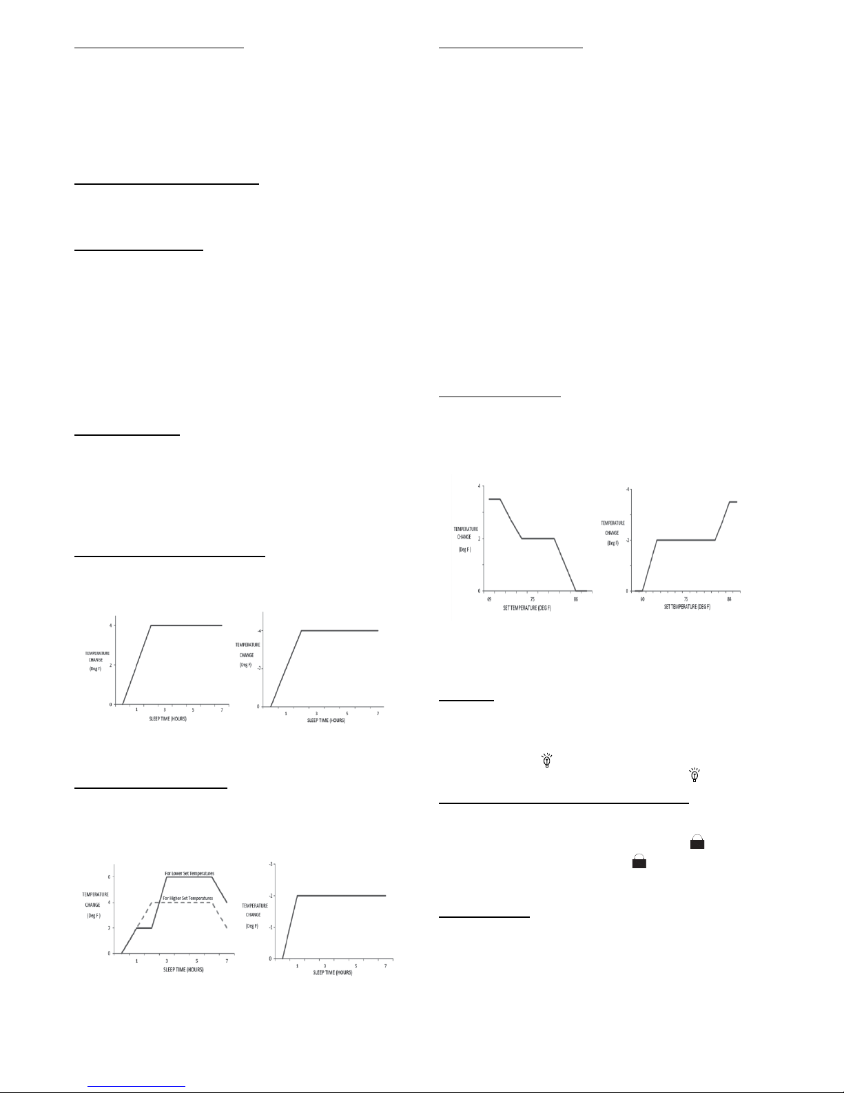
TRADITIONAL MODE - SLEEP 1
In Traditional Mode the unit slowly relaxes the room set
temperaturebyupto4_F until Sleep Mode is cancelled.
Cooling Mode Heating Mode
Fig. 10 - Cooling and Heating Modes
EXPERT MODE - SLEEP 2
In Expert Mode the unit adjusts the room set temperature at a rate
based on the starting set temperature value. Sleep Mode continues
until cancelled.
Cooling Mode Heating Mode
Fig. 11 - Cooling and Heating Modes
DIY MODE SLEEP 3
You are required to enter eight (8) room set point values for eight
(8) hours of run time. The last room set point value is maintained
until the sleep mode is cancelled.
In Sleep Mode 3, press the “Prog” button to enter the setup mode.
The remote controller displays “1:00” in the time location. Use the “+”
and “- “ buttons to select the desired room set point for the first hour
of run time. Then press the “Prog” button to save the set point.
Repeat this sequence for the eight (8) room set point values. After
all eight (8) values have been entered, the remote controller
automatically reverts to standard time and temperature display, and
the Sleep 3 Mode starts.
At any time, you may press the “ON/OFF,” “Mode,” “Timer,”
“Sleep” or “Turbo” buttons to cancel the Sleep 3 Mode.
NOTE: During this procedure, if no button is pressed within 10
seconds, the remote controller automatically exits the sleep
curve setting and resumes the original display. If the ON/OFF,
MODE, TIMER, SLEEP, COOLING or HEATING button is
pressed during the setting or inquiry procedure, the remote
controller exits the sleep curve setting.
SIESTA MODE 4:
In Siesta Mode the unit automatically changes the room
temperature every 30 minutes based on the room temperature
setting. The Sleep Mode continues until cancelled.
Cooling Mode Heating Mode
Fig. 12 - Siesta Mode
NOTE: Sleep function can not be set in AUTO mode.
LIGHT:
This function allows the user to turn the display ON or OFF on
the front panel.
Press the light icon to turn the indoor unit front panel ON or
OFF. The remote control displays the Light Icon .
Combination of “+” and “- ” Buttons:
Press “+” and “- ” buttons simultaneously for 8 seconds to lock or
unlock the keypad. If the remote control is locked, is displayed.
In this case, pressing any button, blinks three times to
acknowledge the keypad is locked. Repeat the process to unlock
the remote controller.
WIFI Button:
Press and hold this button for three seconds to turn WIFI function
on or off. See the “Operation of Smart Control” section for more
information.
Only the set point temperature appears on the front panel and on
the remote controller.

8
CLEANING, MAINTENANCE AND TROUBLESHOOTING
ELECTRICAL SHOCK HAZARD
Failure to follow this caution may result in personal injury
or death.
Always turn off power to the system before performing any
cleaning or maintenance to the system. Turn off the outdoor
disconnect switch located near outdoor unit. Be sure to
disconnect indoor unit if on a separate switch
CAUTION
!
EQUIPMENT DAMAGE/OPERATION HAZARD
Failure to follow this caution may result in equipment
damage or improper unit operation.
Operating the system with dirty air filters may damage the
indoor unit and could cause reduced cooling performance,
intermittent system operation, frost build- up on indoor coil
or blown fuses.
CAUTION
!
Periodic Maintenance
Periodic maintenance is recommended to ensure proper operation
of the unit. Recommended maintenance intervals may vary
depending on the installation environment, e.g., dusty zones, etc.
Refer to Table 1.
CUT HAZARD
Failure to follow this caution may result in personal injury.
The coil fins are very sharp. Use caution when cleaning.
Always wear safety protection.
CAUTION
!
Cleaning the Coil
Clean the coil at the beginning of each cooling season, or when
necessary. Use a vacuum cleaner or a long- bristle brush to avoid
damage to the coil fins.
Air Filters
Remove and clean the air filters once a month.
NOTE: If air filters show signs of excessive wear or are torn, they
must be replaced. Contact your local dealer for replacement filters.
1. Open front panel on unit.
2. Pull filters down to remove.
3. Vacuum filters.
4. Clean with warm water.
5. Shake filter to remove excess water and dry thoroughly.
6. Replace filter by sliding into rack until filter snaps in place.
7. Close front panel on unit.
EQUIPMENT DAMAGE HAZARD
Failure to follow this caution may result in equipment
damage.
When cleaning the front panel, do not use water hotter than
105_F (40.56_C) and do not pour water onto the fan coil.
Do not use abrasive or petroleum based cleaners as they
may damage the front panel.
CAUTION
!
Indoor Unit Front Panel
To clean the front panel on the indoor unit, wipe the outside with
a soft, dry cloth. If necessary, a mild liquid detergent can be applied
and wiped off with a dry cloth.
Preparing for Extended Shutdown Period
Clean the filters and reposition them in the unit. Operate the unit
in Fan only mode for 12 hours to dry all internal parts.
Turn main power supply off and remove batteries from the remote
control.
System Operation Recommendations
The items outlined in the following list helps to assure proper
system operation:
SReplace both remote control batteries at the same time.
SPoint the remote control toward the unit display panel when
transmitting a command.
SKeep doors and windows closed while unit is operating.
SContact an authorized service representative if a problem arises
that cannot be easily resolved.
SDo not perform cleaning or maintenance activities while unit
is on.
SKeep display panel on unit away from direct sunlight and heat
as this may interfere with remote control transmissions.
SDo not block air intakes and outlets on the indoor or outdoor
units.
Energy Saving Recommendations
The following recommendations add greater efficiency to the
ductfree system:
SSelect a comfortable thermostat setting and leave it at chosen
setting. Avoid continually raising and lowering the setting.
SKeep unit filter clean. Frequent cleaning may be necessary
depending on indoor air quality.
SUse drapes, curtains or shades to keep direct sunlight from
heating room on very hot days.
SDo not obstruct air intake on front panel.
STurn on air conditioning before indoor air becomes too
uncomfortable.
Troubleshooting
Refer to Table 2 before contacting your local dealer.

9
Table 1—Periodic Maintenance
INDOOR UNIT EVERY 3 MONTHS EVERY 6 MONTHS EVERY YEAR
Clean Air Filter*
Change Remote Control Batteries
S
S
S
OUTDOOR UNIT EVERY 3 MONTHS EVERY 6 MONTHS EVERY YEAR
Clean Outdoor Coil from Outside
Clean Outdoor Coil from Inside†
BlowAirOverElectricParts†
Check Electric Connection Tightening†
Clean Fan Wheel†
Check Fan Tightening†
Clean Drain Pans†
S
S
S
S
S
S
S
* Increase frequency in dusty zones.
{Maintenance to be carried out by qualified service personnel. Refer to the Installation Manual
Table 2—Troubleshooting
PROBLEM POSSIBLE CAUSE SOLUTION
Indoor unit emits a bad odor on
start- up
Air filter dirty
Output air still has odor after cleaning filter.
Clean the air filter
Contact your service representative.
You hear water flowing noise
when the unit is running
This is normal and is the refrigerant flowing
through the system.
No maintenance required
Indoor unit produces a mist
when the air conditioner is
running
This is normal cooling and is caused by high
humidity and temperature in the room.
No maintenance required. Mist should stop as
room is cooled down and the humidity is removed.
Wireless remote control does
not work
Batteries are dead.
Unit needs to be reset.
See battery replacement section in this manual
and replace batteries.
Turn off power to indoor unit. Remove plug from
wall and then reinsert plug. Restart unit.
Water leaks into room from
Indoor unit
Condensing water has overflowed Check indoor condensing drain or call your
representative.
Unit/System Does Not Work To protect the unit upon an immediate restart
after a stop, the system controller delays
the unit for 3 minutes before allowing the unit
to start back up.
The circuit breaker has tripped or a fuse
has blown.
Power failure.
Error codes displayed
Voltage is too low.
After turning unit off, wait at least 3 minutes before
trying to restart.
Reset the circuit breaker or replace the fuse with
the specified replacement fuse.
Restart operation when the power is restored.
Call your service representative.
Cooling is Not Working
Properly
The filter is blocked with dust.
Temperature is not set properly.
A window or door is open.
The outdoor unit is obstructed.
The fan speed is too low.
The operation mode is in Fan instead of
Cool.
Clean the air filter.
Check the temperature and reset if necessary.
Close the window or door.
Remove the obstruction.
Change the fan speed selection.
Change the operating mode to Cool or reset the
unit.
Heating is Not Working
Properly
The filter is blocked with dust.
Temperature is set too low.
A window or door is open.
The outdoor unit is obstructed.
Clean the air filter.
Check the temperature and reset if necessary.
Close the window or door.
Remove the obstruction.
Unit Stops During Operation The Off timer is not operating correctly.
Error codes displayed
Restart the operating mode.
Call your service representative.

10
Copyright 2015 International Comfort Products Lewisburg, TN 37091 USA
Manufacturer reserves the right to change, at any time, specifications and designs without notice and without obligations.
Catalog No:42102923001
Replaces:42102923000
Edition Date: 06/15
Table of contents
Other KeepRite Air Conditioner manuals