KEF KMPS-7 User manual

KMPS-7 Owners Manual
Thank you for selecting the KEF KMPS-7 Power Supply. The KMPS-7 is designed for a plug and play installation when used with
KEF motori ed custom installation speaker model Ci200.3Qt (and Ci3-80Qt in the near future). The KMPS-7 will also simplify the
installation of all previous models and versions of KEF motori ed speakers. The KMPS-7 may also be used to activate other devices
in an installation, that utili e a standard 12VDC trigger such as TV lifts, drop down screens and motori ed drapes and blinds.
What’s in the box?
Please inspect the contents of the KMPS-7 carton carefully before installation. You will find the KMPS-7 Power Supply, The main
power cord with a standard 3 prong connection at each end (much like a computer power cord), A secondary 2 prong line cord for
use when selecting the Switched Outlet Trigger Method (See Trigger Options section), and an 1/8” (3 mm) male-to-male mono
mini plug cable for use when selecting the Recei er 12V Trigger Method (See Trigger Options section), 4 Self Stick Rubber Feet
and 2 rack adaptors with screws to attach them to the KMPS-7.
Placement
You can either sit the KMPS-7 on a shelf or use the Rack Adaptors to mount the unit to a standard rack system or within a piece of
furniture with mounting rails. The body of the KMPS-7 is 17” wide to accommodate standard EIA rack systems. With the Rack
Adaptors mounted to the unit, the total width is 19”. If simply sitting the unit on a shelf, please attach the 4 Self Stick Rubber Feet to
the four corners of the bottom of the unit. Do not place the KMPS-7 on other heat producing components since it may cause the unit
to overheat.
For Rack Mounting the KMPS-7, attach the Rack Adaptors to the unit using the 8 screws included. You will need to furnish the
Rack mounting screws for your particular rack or mounting rails. Do not mount the KMPS-7 directly above another heat producing
component since it may result in overheating.
Front Panel Controls
Main Power Switch – This switch is used to power the KMPS-7 on and off.
Manual Activation Switch – This switch is used to activate and deactivate the motori ed speaker connected to the
KMPS-7. If no Trigger Option is used, this switch can be used to manually drop and raise the motori ed speakers connected to it
on demand. The switch can also be used to test the function of the speakers prior to completing the entire home theater
installation and set up. When a regular trigger option is selected using one of the trigger connections on the rear panel, this
switch should be kept in the “Up” position. The Manual Activation Switch will override any other trigger options selected. If the
switch is left in the “Down” position it may give the impression that trigger method selected isn’t working. Always keep this
switch in the “Up” position when using any other trigger option.

KMPS-7 Owners Manual
Rear Panel Connections
Caution: Please make all trigger and speaker connections before connecting the KMPS-7 Mains Power cord to the wall
outlet. Be sure that your home theater recei er is turned off.
Seven RJ-45 Female jacks for connecting KEF motori ed speaker model Ci200.3Qt (and Ci3-80Qt in the near future)
using standard CAT5 straight through cables. Important Note: These jacks are NOT to be used to make a connection to a
computer network or directly to a computer despite similarity to those connections found on many of those de ices.
Although the jacks are designed to cause no harm to such de ices, not all computer hardware implementations of the
RJ-45 jack are correct and damage to the computer or network de ice may still occur.
The cables used to connect the motori ed speaker to the KMPS-7 must be “straight through” standard CAT5 (or better)
cables. These cables are NOT included with the KMPS-7 since the number of cables and length will vary for each
installation. You may use either pre-terminated CAT5 cables available from your favorite technology retailer or you may
make and terminate your own cables using CAT5 cable (or better) and modular ends (see diagram and table below).
RJ45 Pin Number Wire Color for CAT5 KEF Speaker Use
1 White/Orange N/A
2 Orange/White N/A
3 White/Green Trigger (Green on KEF motori ed spkrs)
4 Blue/White +12V (Red on KEF motori ed spkrs)
5 White/Blue +12V (Red on KEF motori ed spkrs)
6 Green/White N/A
7 White/Brown Ground (Black on KEF motori ed spkrs)
8 Brown/White Ground (Black on KEF motori ed spkrs)
Note: The brown/white and white/brown pair are used together for Ground (-) connections and the blue/white and
white/blue pair are used together for the +12V connection to the KEF motori ed speakers.
Up to seven motori ed speakers can be connected to this set of jacks. Do not use splitters or home made “Y” connectors to
connect more than seven speakers since the jacks and standard CAT5 wiring are not designed to handle the electrical
requirements of more than one speaker on a single CAT5 wire. When designing your installation, you should use a home run of
CAT5 for each motori ed speaker being used.
You can use the power supply Binding Post Terminals for connecting additional devices and speakers. Please see the
appropriate Binding Post Terminal section of this manual for additional information.
Trigger Options
There are two different trigger options that may be selected to allow an automated drop down of the KEF motori ed speaker
models and any other 12VDC triggered devices connected to the KMPS-7. The first option takes advantage of a 12VDC trigger
jack available on many modern home theater receivers. When available on a home theater receiver, this jack is a 1/8” (3 mm)
female type that will accept one end of the 1/8” (3 mm) male-to-male cable included with the KMPS-7 When this jack is
available it should be labeled “Trigger” on the home theater receiver.
Important Note: Some recei ers ha e similar jacks which are labeled “IR In” or “IR Out”. Do NOT use these for the
12VDC trigger option as damage to the recei er may occur. There are some home theater recei ers that pro ide a
“Trigger” jack that is only a ailable for Zone 2 use. These jacks may not pro ide the needed trigger for proper operation
of the KMPS-7.

KMPS-7 Owners Manual
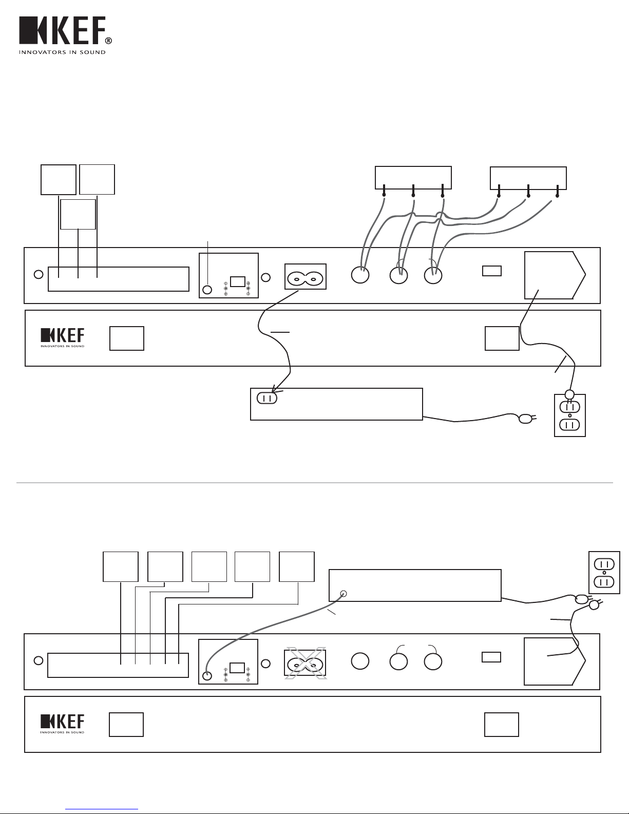
If a proper “Trigger” jack can not be located on the home theater receiver, use the second trigger option which uses the
“Switched Outlet” that exists on virtually all receivers. The Switched Outlets on such receivers are energi ed when the receiver
itself is switched ON and de-energi ed when the receiver is switched OFF. This method of triggering will cause the KEF
motori ed speakers to activate when the receiver is turned ON and return to their up position when the receiver is turned OFF.
See the connections below for further details.
Important Note: Please make only one connection to the trigger option jacks or , but not both. Only one trigger
method can be used at a time. If you’re not sure of whether you ha e a proper “Trigger” jack on your recei er, please
use the Switched Outlet trigger only.
& Recei er 12VDC Trigger Option
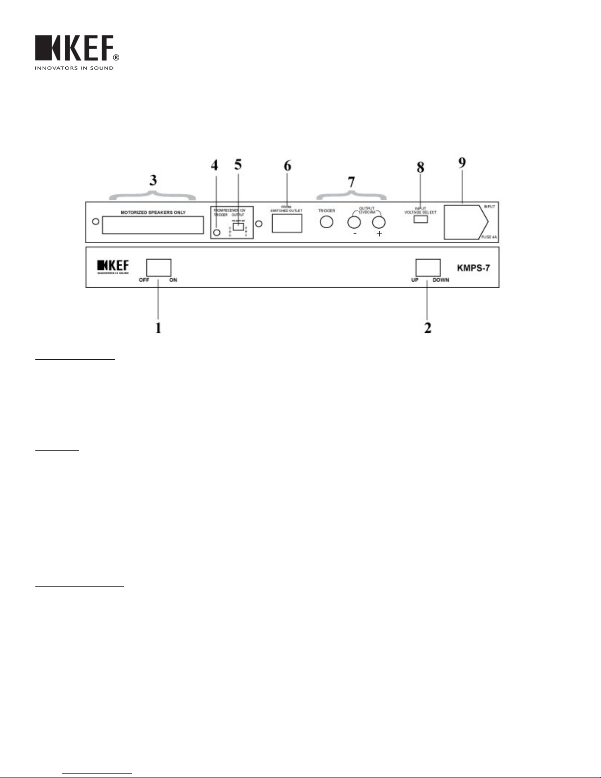
When you have selected the Receiver 12VDC Trigger option, connect one end of the 1/8” (3mm) male-to-male mono cable to
the jack on the rear panel of the KMPS-7. Connect the other end to the jack on the home theater receiver labeled “Trigger” or
“12VDC Trigger”. When this method is used, DO NOT connect anything to the “From Switched Outlet” trigger jack on the
rear panel of the KMPS-7. The switch next to the “From 12V Trigger Output” jack is used to allow connection to
receivers that use an unconventional polarity of the trigger output voltage the receiver supplies. Most receivers will use a
positive (+) tip and negative (-) ring polarity which would require the switch to be in the RIGHT most position. This is the
default setting when the KMPS-7 leaves the factory.
Important Note: When using the 12VDC Trigger option, the oltage supplied to all triggers a ailable on the KMPS-7
comes from the recei er “Trigger” jack. This oltage is frequently current limited on most recei ers to 25mA (although
some newer units pro ide up to 50mA). The KEF motorized models require ery little trigger current (less than 3mA on
all current models) which means that e en with 7 speakers connected to all of the jacks on the KMPS-7, the total
current will stay below the maximum of 25mA a ailable on many recei ers. If you wish to use other de ices with the
KMPS-7, please check with the manufacturer of those de ices to be sure that the trigger current requirements don’t
cause the total to exceed that supplied by the recei er. If you’re not sure about these requirements, please use the
Switched Outlet Trigger option which will draw its trigger current from the KMPS-7 itself and is limited only by the
total current capabilities of the KMPS-7 (which is 6Amps).
If the receiver that you’re using uses the unconventional polarity of negative (-) tip and positive (+), please move this switch
to the left most position for negative tip and positive ring.
Important Note: Please use a olt meter or check with the manufacturer of your recei er to determine the polarity of this
trigger connection. Incorrect polarity of this connection will pre ent proper operation of the KMPS-7 and may cause
damage to the recei er or the KMPS-7.
Important Info: Some recei ers allow you to “map” whether the trigger jack on the rear panel of the recei er acti ates
on any gi en input selected on the recei er. One major brand, as a default, only acti ates the trigger jack on the rear
panel when a Video source is selected, such as TV or DVD. Be sure that you ha e a ideo source, like DVD, selected
when testing your installation. If the CD input is chosen, you may belie e that a problem exists with the power supply
when in fact it is simply because the “Trigger” jack is not being acti ated on the recei er. When this feature is a ailable,
it is almost always something that can be changed to work the way you want it to from the menu system of the recei er.
Please check the owner’s manual of the recei er to determine how yours works.

KMPS-7 Owners Manual
Switched Outlet Trigger Option
When you have selected the Switched Outlet Trigger option, connect the included 2 prong AC line cord to the jack on the
rear panel of the KMPS-7 and the other end to the “Switched AC Outlet” on your receiver (these AC outlets on the rear panel of
the home theater receiver are sometimes simply labeled “SW” and “UnSW” – in this case used the one labeled “SW”). If this
trigger option is selected, DO NOT connect anything to the Receiver 12V Trigger jack on the KMPS-7. Important Note: If
you plug the 2 prong cable into the Unswitched outlet a ailable on some recei ers the trigger will be acti ated all the time
and the speakers will not go up. Please be sure to use only a connection to the Switched outlet of the recei er.
Extra Power and Trigger Output Connections
The three binding posts available on the rear of the KMPS-7 can be used for older KEF motori ed speakers without the
RJ-45 jacks on them or models like the Ci-FDT dipole surround motori ed KEF model. For your convenience, the color code of
these binding posts matches the wiring color code on the older KEF models. These connections can also be used for other
devices that may require a 12VDC power supply and trigger such as TV lifts and motori ed screens, blinds and drapes. The Red
and Black binding posts provide a continuous 12VDC which is always on when the KMPS-7 Power Switch is “On”. Red is
Positive (+) and Black is Negative (-). The total current capacity of the KMPS-7 is 6 Amps. The Green Trigger binding post
will provide a continuous 12VDC trigger voltage whenever either the trigger jack on the receiver is active or the switched outlet
on the receiver is ON, depending on the trigger option being used. The Green binding post is the Positive (+) of the trigger
voltage, the Black binding post is the Negative (-). The Black binding post is a shared ground for both the continuous power and
the trigger.
Mains Voltage Selection and Power Cord Connections
This switch is used to select the AC Input Voltage for the Main Connection Only. It is set to 115VAC at the factory. The
unit can be used on 230VAC by moving the switch to the 230V position. The oltage selector is only for the purpose of
changing the Mains oltage on the KMPS-7. Should this unit be used on a 230VAC circuit, you must use a small
con ersion transformer to “step down” the oltage from a Switched Outlet on a recei er designed for use on 230VAC
and pro iding 230VAC at the switched outlet on the rear panel of the recei er. The step down transformer must change
the switched outlet oltage from 230VAC to 115VAC before being connected to the two prong “From Switched Outlet”
jack on the KMPS-7. It is highly recommended that you use the Recei er 12VDC Trigger option when using the
KMPS-7 with 230VAC mains. Please call 732-683-2356 for further guidance with this feature. Please note that the
Mains fuse in jack must be changed from a 4Amp to a 2Amp fuse if the oltage selector is changed to 230VAC.
Connect the main 3 prong power cord included with the KMPS-7 to this jack. The jack provides an integrated fuse to
protect the KMPS-7 from damage caused by over current situations. If the fuse opens and the unit does not appear to operate,
please replace it with an identical fuse of 4 Amps. If the fuse blows immediately, please disconnect the main 3 prong power
cord and all other connections from the KMPS-7 and stop using it. Call our Service Department at 732-683-2356 to arrange for
an evaluation and service of the unit. DO NOT use a fuse rated higher than 4Amps and do not use SLO-BLO fuses with this
power supply.

- +
MOTORIZED SPEAKERS ONLY FROM RECEIVER 12V
TRIGGER OUTPUT
POLARITY SW
FROM
SWITCHED OUTLET TRIGGER OUTPUT
12VDC/6A
INPUT
VOLTAGE SELECT
INPUT
FUSE 4A
OFF ON UP DOWN
KMPS-7
KMPS-7 Configuration Options
Ci 200.3
QT
Ci 200.3
QT
Ci 200.3
QT
}
Straight
through CAT5
w/ RJ45 Ends
X
NOT USED
YOUR RECEIVER
Switched
AC Outlet
Unswitched
Wall Outlet
GREEN GREEN
BLACK BLACK
RED RED
Preferred Triggering Method
for mix of Ci200.3QT w/ legacy products
(Ci3-80QT, CiFDT, or Ci200.2QT)
- +
MOTORIZED SPEAKERS ONLY FROM RECEIVER 12V
TRIGGER OUTPUT
POLARITY SW
FROM
SWITCHED OUTLET TRIGGER OUTPUT
12VDC/6A
INPUT
VOLTAGE SELECT
INPUT
FUSE 4A
OFF ON UP DOWN
KMPS-7
Ci 200.3
QT
12VDC Trigger Diagram
Ci 200.3
QT
Ci 200.3
QT
Ci 200.3
QT
Ci 200.3
QT
Straight
through CAT5
w/ RJ45 Ends
X
NOT USED
}
YOUR RECEIVER
Unswitched
Wall Outlet
12VDC
TRIGGER OUT
1/8” Mono Mini
Plug Wire (Included)
Ci 3-80QT Ci 3-80QT
Switched outlet
trigger cord
(Included).
AC linecord
(Included).
AC linecord
(Included).

- +
MOTORIZED SPEAKERS ONLY FROM RECEIVER 12V
TRIGGER OUTPUT
POLARITY SW
FROM
SWITCHED OUTLET TRIGGER OUTPUT
12VDC/6A
INPUT
VOLTAGE SELECT
INPUT
FUSE 4A
OFF ON UP DOWN
KMPS-7
KMPS-7 Configuration Options
X
NOT USED
YOUR RECEIVER
Switched
AC Outlet
Unswitched
Wall Outlet
Switched Outlet Trigger Diagram
Ci 200.3
QT
Ci 200.3
QT
Ci 200.3
QT
Ci 200.3
QT
Ci 200.3
QT
Straight
through CAT5
w/ RJ45 Ends
}
continued
Switched outlet
trigger cord
(Included).
AC linecord
(Included).
Table of contents