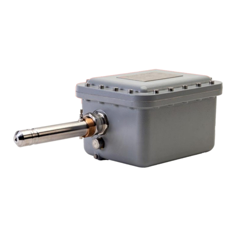
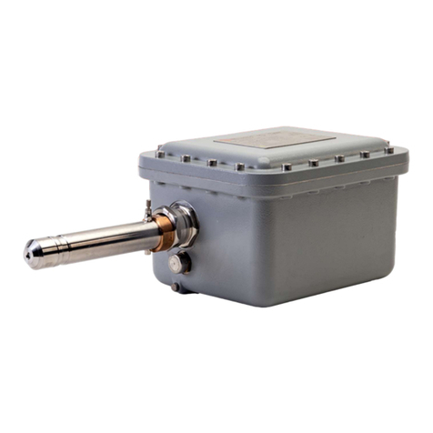
Keit IRmadillo User manual

DOC0535
10 July 2019, 16:56
www.keit.co.uk
User Manual
Rugged FTIR Spectrometer for Real-Time Process Analysis

User Manual Page 2
www.keit.co.uk DOC0535 10 July 2019, 16:56
Table of Contents
Table of Contents.....................................................................................................2
Contact Keit..............................................................................................................6
1. Introduction........................................................................................................7
1.1 Introduction to the IRmadillo ...................................................................................7
1.2 Brief introduction to infrared spectroscopy..............................................................7
1.3 How FTIR spectrometers work................................................................................8
1.4 What makes the IRmadillo different? ......................................................................8
2. System overview................................................................................................9
2.1 System configuration ............................................................................................10
2.2 Controller..............................................................................................................10
2.3 Software ...............................................................................................................10
3. Safety................................................................................................................11
3.1 General safety ......................................................................................................11
3.2 Lifting instructions.................................................................................................11
3.3 Electrical safety.....................................................................................................12
3.4 Hazardous environment safety –Ex-certified models............................................12
3.5 Pressure safety notes...........................................................................................14
3.6 Ventilation and location.........................................................................................14
4. Installation........................................................................................................15
4.1 Installation location ...............................................................................................15
4.2 Spectrometer components....................................................................................16
4.2.1 Product label (A)............................................................................................16
4.2.2 Probe purge outlet (B)....................................................................................17
4.2.3 Probe (C).......................................................................................................17
4.2.4 ATR Element (D) ...........................................................................................17
4.2.5 Breather (E)...................................................................................................17
4.2.6 Earthing point (F)...........................................................................................17
4.2.7 Probe purge inlet (G) .....................................................................................17
4.2.8 Spectrometer body purge inlet (H).................................................................17
4.2.9 Communication port (I) ..................................................................................17
4.2.10 Power cable port (J).......................................................................................18

User Manual Page 3
www.keit.co.uk DOC0535 10 July 2019, 16:56
4.2.11 Mounting holes (K).........................................................................................18
4.3 Connection to a vessel or pipeline for measuring..................................................19
4.3.1 Fluid tight seal to the instrument ....................................................................19
4.4 Electrical installation .............................................................................................20
4.4.1 Uninterruptible power supply (UPS)...............................................................20
4.4.2 Ensuring a power connection to the spectrometer .........................................20
Table 1 –IRmadillo power specifications .....................................................................20
4.4.3 Connecting the power cable to the instrument ...............................................21
4.5 Data communication connection...........................................................................23
4.5.1 Connecting the data communication cable to the spectrometer .....................23
4.5.2 Connecting the USB communication cable to the controller...........................23
4.5.3 Connecting the fibre data communication cable to the controller....................24
4.6 Purging the unit.....................................................................................................25
4.7 Stabilisation period................................................................................................26
5. Using the system and software......................................................................27
5.1 Software version: 4.0.7.........................................................................................27
5.2 Getting started......................................................................................................27
5.2.1 Manual sample acquisition.............................................................................27
5.2.2 Continuous collection.....................................................................................27
5.2.3 Collect a background scan.............................................................................27
5.2.4 Manual sample acquisition.............................................................................29
5.2.5 Monitoring a reaction or process....................................................................30
5.3 The Spectrometer tab...........................................................................................31
5.4 Manual sample acquisition....................................................................................36
5.5 Configure acquisition ............................................................................................41
5.6 Batch viewer.........................................................................................................44
5.7 Reaction monitor...................................................................................................49
5.8 Configure chemometrics.......................................................................................51
5.8.1 Supported model types..................................................................................53
5.8.2 Editing Camo model settings .........................................................................54
5.8.3 Common chemometrics errors.......................................................................55
5.9 Log viewer ............................................................................................................56
5.10 Offline viewer........................................................................................................59
6. Data communication integration and configuration.....................................60

User Manual Page 4
www.keit.co.uk DOC0535 10 July 2019, 16:56
6.1 Modbus communications ......................................................................................60
6.1.1 Configure Keit controller ................................................................................60
6.1.2 Holding registers............................................................................................62
6.1.3 Representation of data in Modbus .................................................................62
6.1.4 Modbus RTU tutorial......................................................................................63
6.2 Modbus TCP server..............................................................................................66
6.2.1 Getting started with Modbus TCP ..................................................................67
6.3 OPC-UA................................................................................................................68
6.3.1 Licensing the OPC-UA server........................................................................69
6.3.2 UaExpert client ..............................................................................................70
6.3.3 OPC address space.......................................................................................70
6.4 Controller administrator guidance .........................................................................73
6.5 Connecting the spectrometer to Camo Analytics’ Process Pulse ..........................74
7. Maintenance.....................................................................................................76
7.1 Service and support contacts................................................................................76
7.2 Preventative maintenance and service intervals ...................................................76
7.3 Protecting and cleaning the dip probe ATR element .............................................76
7.3.1 Cleaning instructions: infrared glass probes...................................................77
7.3.2 Cleaning instructions: diamond probes ..........................................................78
7.4 Cleaning prior to Sterilise-in-Place (SIP)...............................................................79
7.5 ATR and O-ring.....................................................................................................79
7.6 Cleaning the fibre optic data cable connectors......................................................79
7.7 Troubleshooting....................................................................................................82
7.8 Remote Health Check...........................................................................................83
7.8.1 Remote access..............................................................................................83
7.8.2 Sending data manually ..................................................................................84
8. Accessories......................................................................................................85
8.1 Sample cell...........................................................................................................85
8.2 Flow cell................................................................................................................86
8.2.1 Introduction....................................................................................................86
8.2.2 Safety ............................................................................................................86
8.2.3 Specifications and safety limits (flow cell) ......................................................87
8.2.4 Installation .....................................................................................................88
8.2.5 Maintenance..................................................................................................91

User Manual Page 5
www.keit.co.uk DOC0535 10 July 2019, 16:56
8.2.6 Cleaning ........................................................................................................92
8.3 Flanged probe (Ex certified)..................................................................................93
8.3.1 Introduction....................................................................................................93
8.3.2 Safety ............................................................................................................93
8.3.3 Specifications and safety limits (welded flange probe)...................................94
8.3.4 Installation .....................................................................................................94
8.3.5 Maintenance..................................................................................................96
Appendix 1: Technical Specification Sheet (Model ASM0627, Ex-Certified
IRmadillo)................................................................................................................97
Appendix 2: Controller Specifications ................................................................98
Appendix 3: Technical Drawings IRmadillo...................................................... 101
Appendix 4: Declarations of Conformity............................................................104
Declaration of Conformity - IRmadillo (Ex-Certified Spectrometer) ................................104
Declaration of Conformity - Controller............................................................................105
Declaration of Conformity –Flow Cell............................................................................106
FCC Class A emissions statement ................................................................................107

User Manual Page 6
www.keit.co.uk DOC0535 10 July 2019, 16:56
Contact Keit
Website: www.keit.co.uk
Postal address: Keit Ltd.
Unit 4, Zephyr Building
Eighth Street, Harwell Campus
Didcot
Oxfordshire
OX11 0RL
United Kingdom
Telephone number: +44 (0) 1235 431260
The triangle symbol on the product label means essential safety information
must be followed to prevent user injury or damage to the instrument. Before
installing or using the product the user must refer to and comply with the safety
notices in Section 3.

Page 7
www.keit.co.uk Introduction: DOC0535 10 July 2019, 16:56
Back to Table of Contents
1. Introduction
1.1Introduction to the IRmadillo
The IRmadillo is a vibration-tolerant, mid-infrared process spectrometer designed to enable
monitoring of either batch or continuous processes of liquids in a range of industries.
The IRmadillo has no moving parts and a rigid probe which is inserted directly into the reaction
vessel or process pipeline for continuous real-time analysis. The device is tolerant of extreme
vibration levels. The spectrometer can be combined with either multivariate analysis (i.e.,
chemometrics), or univariate analysis (i.e., peak height tracking) to act as a concentration
meter. This allows for accurate monitoring of a process/reaction state in real time at the point
of production.
1.2 Brief introduction to infrared spectroscopy
Spectroscopy is the study of how molecules interact with light. There are many different types
of spectroscopy spanning a wide range of light wavelengths (i.e., infrared, UV-visible,
microwave, NMR using radiowaves, and X-ray spectroscopy).
Infrared (IR) spectroscopy is a powerful technique that monitors chemicals by looking at the
vibration of chemical bonds. Different molecular bonds –and therefore chemical components
–can be identified at various parts of the infrared spectral range from near-infrared (NIR), to
mid-infrared (MIR) and far-infrared. Of these, the mid-infrared region is the most information-
rich area of the spectrum and therefore highly desirable for use in analysis.

User Manual Page 8
www.keit.co.uk Introduction: DOC0535 10 July 2019, 16:56
Back to Table of Contents
1.3 How FTIR spectrometers work
Fourier transform infrared spectrometers (FTIRs) use a computational process (Fourier
transform) that interprets the information of an interference pattern (interferogram) in the mid-
infrared region to generate a spectrum.
Conventional FTIR instruments use a Michelson interferometer which consists of a pair of
moving mirrors, designed to split and recombine light into an interference pattern. However,
the moving mirrors make the instrument highly sensitive to vibration, and therefore not suitable
for direct use in industrial environments.
To work aroundthis, some manufacturers have coupled conventional FTIRspectrometers with
long fibre optic probes connected to the instrument which has been removed to a stable safe
zone at some distance. Unfortunately, current fibre optic probe design is known to have a
fragile natureandis prone to performance failure when bent, handled, or twisted; again making
it difficult to achieve real-time process monitoring in a manufacturing environment.
1.4 What makes the IRmadillo different?
The IRmadillo is an FTIR instrument in that it creates an interferogram and requires a Fourier
transform to interpret the information for a spectrum. But rather than using a moving mirror to
create the interferogram it uses a proprietary arrangement of fixed mirrors to create an
interference pattern.
Unlike conventional FTIR spectrometers, the IRmadillo has no moving parts, making it
extremely resistant to vibration and therefore able to be used directly in the manufacturing
environment. It can be fixed directly onto the side of a reaction vessel or pipe at the point of
production rather than remotely located. This enables manufacturers to continuously monitor
their chemical reactions in real time with an in-line analytical instrument. The IRmadillo is an
innovation in process analytical technology that changes how manufacturers can monitor and
control their processes.

User manual Page 10
www.keit.co.uk System overview: DOC0535 (10 July 2019, 16:56)
Back to Table of Contents
2.1 System configuration
The following communication protocols with the distributed control system (DCS) are currently
supported:
•OPC-UA over Ethernet
•Modbus RTU over RS-485 or RS-232
•Modbus TCP over Ethernet
•Others: contact Keit Ltd.
Historical records of spectra and detailed instrument diagnostics are stored locally on the
controller for preventative maintenance and fault finding.
The logfile is a record of registered events, configuration changes and errors.
The Data Link to the DCS allows only minor configuration changes. Significant changes can
only be made by logging into the controller locally using a keyboard, visual display unit (VDU),
and mouse.
2.2 Controller
The controller is delivered with the spectrometer software (Keit Spec) pre-installed. The
standard industrial controller allows direct connection of the system cables.
The controller is an industrial-grade computer which performs signal processing and provides
spectra and chemometrics data to the DCS.
2.3 Software
See Section 5 Using the system and software for full details. The controller uses the Microsoft
Windows 10 IOT operating system. It comes pre-configured with the following software:
Keit Spectrometer
(Keit Spec)
This auto-runs on startup and is the default application. It allows
viewing and saving of real-time data.
Project Viewer
For viewing of previously recorded spectra and diagnostics
information.
Log file viewer
For viewing the log of user interaction with the system

Page 11
www.keit.co.uk Safety: DOC0535 (10 July 2019, 16:56)
Back to Table of Contents
3. Safety
The term “WARNING” is used to inform you about situations that could result in personal
injury to yourself or other persons. The term “CAUTION” is used to inform you about situations
that could result in damage to the spectrometer or other equipment.
Failure to follow the requirements shown in this section may lead to the safety of the
equipment being compromised.
3.1 General safety
WARNING
The spectrometer weighs ~18 kg; take care when handling it
to avoid injury.
CAUTION
Do not operate outside the specified range of environmental
or analyte conditions specified on the product label.
CAUTION
The probe is NOT a carry handle; it will be damaged if used to
support the instrument.
CAUTION
Do not open the spectrometer.
3.2 Lifting instructions
The instrument can be carefully lifted by the lip around the top face or with hands underneath
its base. Do not use the probe as a carry handle. It will be damaged if used to support the
instrument. It is the responsibility of the user to suitably risk assess the handling of the
instrument and provide suitable equipment if necessary.

User Manual Page 12
www.keit.co.uk Safety: DOC0535 (10 July 2019, 16:56)
Back to Table of Contents
3.3 Electrical safety
WARNING
The Keit-supplied electrical mains cable must be earthed and
should include a 5A fuse as well as a means of isolating both
live and neutral; obey local electrical safety codes.
WARNING
An additional earth connection must be provided to the
enclosure chassis exterior via the provided M6 screw.
WARNING
Never disconnect the mains power connector when
energised.
CAUTION
Residual current protection or ground fault interrupter
devices are advised.
3.4 Hazardous environment safety –Ex-certified models
WARNING
The spectrometer is sealed at the factory; do not open the
spectrometer.
WARNING
Do not operate outside the range of environmental or analyte
conditions specified on the product label; consult Keit to
check compatibility with your analyte or process conditions.
WARNING
Dust particles must be excluded from the monitored media.
WARNING
The device contains safety-critical breathers; do not restrict
air flow around it.
WARNING
The spectrometer’s Ex protection relies on the gas purge
ports being either plugged or connected to a clean air line. Do
not leave the ports open.
CAUTION
Protect the spectrometer probe tip from impact and under no
circumstances use the probe as a carry handle.
The Ex-certified version of this product (ASM0627-XX) was assessed against the following
standards against the following standards for hazardous environments:
•IEC60079-0 Explosive Atmospheres –Equipment General Requirements
•IEC60079-1 Explosive Atmospheres –Equipment protection by flameproof enclosures
•IEC60079-26 Explosive Atmospheres –Equipment with EPL Ga
In addition, IEC60079-28 Explosive Atmospheres –Protection of equipment using optical
radiation was considered but the equipment is not in the scope of this standard because (ref
section 1, part 5) it has an enclosure that fully contains the optical radiation and provides IP6X
protection in accordance with IEC60529 Degrees of protection provided by enclosures (IP
code).

User Manual Page 13
www.keit.co.uk Safety: DOC0535 (10 July 2019, 16:56)
Back to Table of Contents
Furthermore, elements of IEC60079-31 Explosive Atmospheres –Equipment dust ignition
protection by enclosure have been applied to preclude optical absorbers from entering the
probe.
In accordance with IEC60079-26, the rigid dip probe achieves EPL Ga and can be inserted
into zone 0 environments while the main instrument achieves EPL Gb for use in zone 1. The
user should beaware that creating an opening in azone 0 environmentmay lead to therelease
of flammable gas and flame entrance. EPL Ga is achieved for the dip probe since it is an
enclosure providing protection against dust ignition. The dip probe tube is made of Hastelloy
C-276 or stainless steel 316L. The tip is made of an amorphous infrared (chalcogenide) glass
and provides the interface to liquid analytes. The glass is sealed within the dip probe tube by
means of a perfluoroelastomeric (FFKM) O-ring. Stainless steel, Hastelloy and FFKM are inert
materials and not known to suffer corrosion in most environments.
CAUTION
Infrared glass should not be used in chemicals with pH >9. If in
doubt, consult Keit Ltd.
The following Specific Conditions of Use (also known as X conditions) apply:
•The media to be monitored must be an area where dust particles are excluded
•The dip probe must be mounted so that it is protected from impact
•Contact Keit for advice regarding material compatibility before installing the spectrometer
in a process

User Manual Page 14
www.keit.co.uk Safety: DOC0535 (10 July 2019, 16:56)
Back to Table of Contents
3.5 Pressure safety notes
Do not exceed the pressure or temperature limits stated on the product label as this could be
dangerous and will invalidate the warranty. The suitability of the instrument for various
pressures, temperatures and their rates of change is process dependent (even if the limits are
within those marked on the product label). Contact Keit for advice before installing the
spectrometer in a process.
The ATR element and its O-ring form a pressure boundary. The ATR element is made from
an infrared glass which is fragile. For safe operation it should show no signs of damage; refer
to Section 6 Maintenance for further details.
3.6 Ventilation and location
The spectrometer is thermally stabilised and designed to operate in a variety of conditions and
environments.
WARNING
Purging the instrument with dry nitrogen or air is strongly
recommended for optimum performance (Note: Maximum inlet
gauge pressure of 1 Barg, with a flow rate between 0.5 Litre/min
and 2 Litre/min). When using nitrogen, it is imperative to ensure
adequate ventilation to prevent asphyxiation. The use of an
oxygen sensor is recommended.

Page 15
www.keit.co.uk Installation: DOC0535 (10 July 2019, 16:56)
Back to Table of Contents
4. Installation
4.1 Installation location
The spectrometer is suitable for indoor or outdoor use.
Parameters
Value
Units
Pollution degree of intended
environment
4
Maximum installation altitude
3000
metres
Pollution degree of the environment refers to the level of contamination that the exterior of the
device can cope with. Pollution degree 4 means that continuous conductivity from conductive
dust, rain or other wet conditions will not cause electrical safety to be compromised. The Ex
certifications for this product do not cover protection from flammable or explosive dusts.

User Manual Page 16
www.keit.co.uk Installation: DOC0535 (10 July 2019, 16:56)
Back to Table of Contents
4.2 Spectrometer components
See Appendix 3: Technical Drawings IRmadillo for detailed drawings
4.2.1 Product label (A)
The product label specifies the model of instrument with permissible environmental and
analyte operating conditions, along with applicable certification.

User Manual Page 17
www.keit.co.uk Installation: DOC0535 (10 July 2019, 16:56)
Back to Table of Contents
4.2.2 Probe purge outlet (B)
Allows purge gas to escape the probe.
4.2.3 Probe (C)
The probe is designed to be installed directly into a reaction vessel or pipe and is made of a
non-corroding metal.
4.2.4 ATR Element (D)
The ATR element at the end of the probe is made of an infrared glass that will be damaged
spectrometer in a process.
The material of the ATR element is fragile. It is important to keep the element clean because
this is where the spectrometer interacts with analytes. See page 76 Protecting and cleaning
the dip probe ATR element for more information.
CAUTION
Do not expose the ATR element to alkaline (basic) solutions
with pH > 9 as this will cause irreversible damage to the ATR
and will invalidate the warranty. Contact Keit for advice
regarding material compatibility.
4.2.5 Breather (E)
Do not obstruct the breather.
4.2.6 Earthing point (F)
The spectrometer body has an M6 earth attachment point below the probe. This should be
used in addition to earthing through the power supply cable.
WARNING
Failure to properly earth the spectrometer may cause serious
injury or death.
4.2.7 Probe purge inlet (G)
The spectrometer has been fitted with two 4mm outside diameter (OD) purge inlet ports. One
of these purges the probe. More detail on how to purge the instrument is given on page 25
Section 4.6 Purging the unit.
4.2.8 Spectrometer body purge inlet (H)
The spectrometer has been fitted with two 4mm outside diameter (OD) purge inlet ports. One
of these purges the body. More detail on how to purge the instrument is given on page 25
Section 4.6 Purging the unit.
4.2.9 Communication port (I)
The connectors are specifically designed to work in hazardous zones and have IP65 rating.
More detail on how to connect them to the cables is given on page 23 in section Data

User Manual Page 18
www.keit.co.uk Installation: DOC0535 (10 July 2019, 16:56)
Back to Table of Contents
communication connection. The Spectrometer may be configured to accept a fibre-optic data
cable or a USB cable.
4.2.10Power cable port (J)
The connectors are specifically designed to work in hazardous zones and have IP65 rating.
More detail on how to connect them to the cables is given on page 19 in section Electrical
installation.
4.2.11Mounting holes (K)
The spectrometer should be supported using the four M8 mounting holes inits base. Note that
the spectrometer weighs~18 kg.

User Manual Page 19
www.keit.co.uk Installation: DOC0535 (10 July 2019, 16:56)
Back to Table of Contents
4.3 Connection to a vessel or pipeline for measuring
4.3.1 Fluid tight seal to the instrument
Probe installation into the analyte or process fluid is unique for each application and is not
covered in this user guide. Safe installation of the probe into the process is the responsibility
the user and should be assessed by a suitably trained person.

User Manual Page 20
www.keit.co.uk Installation: DOC0535 (10 July 2019, 16:56)
Back to Table of Contents
4.4 Electrical installation
NOTE
See Page 12 Section Electrical safety prior to attempting installation.
The spectrometer is normally supplied with a blunt-cut mains cable to be wired into your
electrical supply. The instrument requires single-phase mains input and must be connected to
a permanent earth (grounding) connection. A 5A fuse should be fitted in the live/hot supply
connection.
Provide a means of isolating both live and neutral by fitting a disconnecting switch or using a
suitable circuit breaker that meets the requirements of IEC 60947-1 and IEC 60947-3. The
switch must be located within easy reach of the instrument and must be marked as the
disconnection device for the equipment. The disconnecting device must not interrupt the earth
connection.
4.4.1 Uninterruptible power supply (UPS)
Ensure that a reliable power supply is available. An uninterruptible power supply (UPS) is
4.4.2 Ensuring a power connection to the spectrometer
Unless otherwise specified, the power cable will be delivered blunt cut.
The spectrometer is designed to operate over a wide range of voltages shown below in Table
1. If you plan to operate the spectrometer outside of these ranges, contact Keit for advice
before powering up the instrument.
Table 1 –IRmadillo power specifications
Parameters
Value
Units
AC input voltage
100-240
V
AC input frequency
50/60
Hz
Mains supply fluctuations (% of
Nominal Value)
±10
%
Power consumption
100 (max)
W
Overvoltage Category
CAT II
Other manuals for IRmadillo
2
Table of contents
Other Keit Laboratory Equipment manuals