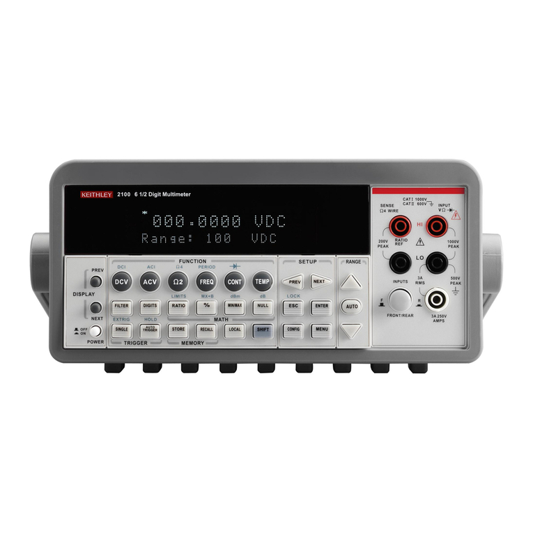
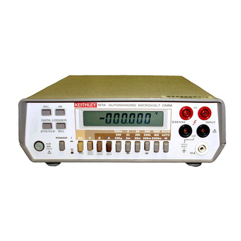
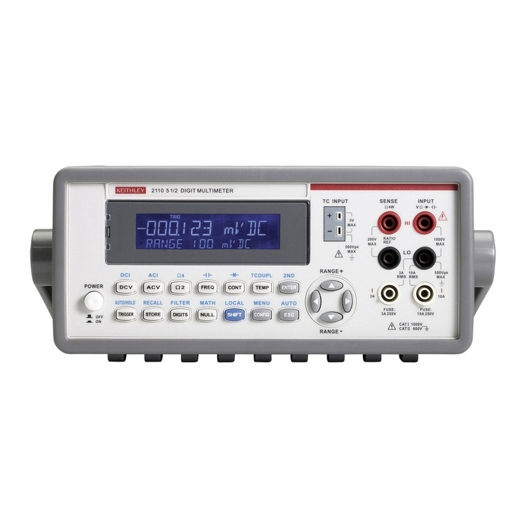
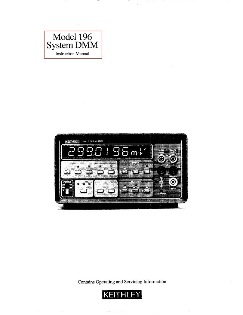
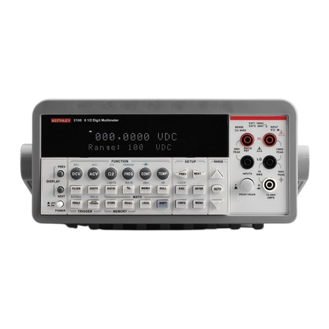
Keithley AUTO-PROBE 167 User manual

INSTRUCTION
MANUAL
MODEL
167
AUTO-PROBE™
DIGITAL
MULTIMETER
ICEITHLEY
irsrSTRU]VnEIS:TS

WARRANTY
We
warrant
each
of
our
products
to
be
free
from
defects
in
material
and
workmanship.
Our
obligation
under
this
warranty
is
to
repair
or
replace
any
instrument
or
part
thereof
which,
within
a
year
after
shipment,
proves
defective
upon
examination.
We
wi
ll
pay
domestic
surface
freight
costs.
To
exercise
this
warranty,
cal
l
your
local
field
representative
or
the
Cleveland
factory,
ODD
216-248-0400.
You
wil
l
be
given
assist
ance
and
shipping
instructions.
REPAIRS
AND
RECALIBRATION
Keithley
Instruments
maintains
a
complete
re
pair
service
and
standards
laboratory
in
Cleve
land,
and
has
an
authorized
field
repair
facil
ity
in
Los
Angeles
and
in
al
l
countries
outside
the
United
States
having
Keithley
field
repre
sentatives.
To
insure
prompt
repair
or
recalibration
serv
ice,
please
contact
your
local
field
representa
tive
or
the
plant
directly
before
returning
the
instrument.
Estimates
for
repairs,
normal
recalibrations,
and
cal
ibrations
traceable
to
the
National
Bu
reau
of
Standards
are
avai
lable
upon
request.

INSTRUCTION
MANUAL
MODEL
167
AUTO-PROBE™
DIGITAL
MULTIMETER
Copyright
Keithley
Instruments,
Inc.1972
0172

CONTENTS
Title
Page
i
Contents
ii
List
of
Illustrations
iii
Specifications
iv
1.
General
Information
1
1-1.
Introduction
.
1
1-2.
Warranty
Information
1
1-3.
Change
Notice
1
1-4.
Applications
2
1-5.
Accessories
2
2.
Initial
Preparation
3
2-1.
General
3
2-2.
Inspection
3
2-3.
Preparation for
Use
3
3.
Operating
Instructions
4
3-1.
General
4
3-2.
Turn-on
Procedure
4
3-3.
Connections
4
3-4.
Function
Selection
6
3-5.
Operation
as
a
Voltmeter
6
3-6.
Operation
as
an
Ohmmeter
8
3-7.
Operation
as
an
Ammeter
10
3-8.
Battery
Operation
12
3-9.
Line
Operation
14
3-10.
Auxiliary
Power
Operation
14
3-11.
Battery
Life
14
3-12.
Display
16
4.
Theory
of
Operation
18
4-1.
General
18
4-2.
Analog
Circuitry
19
4-3.
Digital
Circuitry
20
4-4.
DC
Voltage
Operation
25
4-5.
AC
Voltage
Operation
26
4-6.
OHMS
Operation
27
4-7.
Power
Supply
28
5.
Maintenance
29
5-1.
General
29
5-2.
Required
Test
Equipment.
...
.
...
29
5-3.
Performance
Checks
29
5-4.
Adjustment
and
Calibration
Procedure
.
33
5-5.
Troubleshooting
41
5-6.
Battery
Test
41
5-7.
Battery
Replacement
41
5-8.
Battery
Charging
42
6.
Replaceable
Parts
6-1.
General
45
6-2.
Ordering
Information
45
6-3.
Cross
Reference.
47
6-4.
Parts
List
48
6-5.
Code-to-Name
List.
63
7.
Schematic
Diagrams
65
7-2.
Block
Diagram,
No.
25354D
67
7-3.
Power
System,
No.
25340D
68
7-4.
Analog
Circuitry,
No.
25342D
69
7-5.
Digital
Circuitry,
No.
25343D
70
Appendix
A.
Service
Form
B.
Change
Notice
0172

MODEL
167
ILLUSTRATIONS
ILLUSTRATIONS
Figure
No.
Title
Page
No.
1
Front
Panel
with
Probe
Installed
1
2
Front
Panel
with
Probe
Removed
5
3
Rear
Panel,
Auxiliary
Power
Receptacle
5
4
Operation
as
a
Voltmeter
7
5
Operation
as
an
Ohmmeter
8
6
Measurement
of
Diode
Resistance
9
7
Operation
as
an Ohmmeter
10
8
Digital
Display
11
9
Battery
Installation
13
10
Battery
Compartment
15
11
Overall
Block
Diagram
18
12
Full
Wave
Rectifier
19
13
LSI
Block
Diagram
21
14
A/D
Converter
Block
Diagram
21
15
Identification
of
Segments
24
16
Identification
of
Multiplex
Lines
24
17
DC
Voltage
Operation
25
18
AC
Voltage
Operation
26
19
OHMS
Operation
27
20
Top
Cover
Assembly
34
21
Chassis
Assembly
35
22
Calibration
Controls
37
23
Auxiliary
Power
&
Battery
Check
43
24
Test
Points
on
Circuit
Board
44
25
Component
Layout,
Resistors
53
26
Component
Layout,
Capacitors
54
27
Component
Layout,
Transistors
55
28
Printed
Circuit
PC-307
56
29
Case
Outlines
57
30
Case
Outlines
58
31
Case
Outlines,
Resistor
Networks
59
32
Case
Outline,
LSI-1
60
33
Probe
Assembly
61
0172

SPECIFICATIONS
MODEL
157
SPECIFICATIONS
AS
AN
AUTORANGING
DC
VOLTMETER
RANGE:
+
1
millivolt
per
digit
to
+1000
volts.
ACCURACY:
+0.2%
of
reading
+1
digit
INPUT
IMPEDANCE:
55
megohms
shtmted
by
approximately
220
picofarads.
NMRR:
Greater
than
55
dB
above
50
Hz.
AS
AN
AUTORANGING
AC
VOLTMETER
RANGE:
1
millivolt
per
digit
to
500
volts
rms.
ACCURACY:
Up
to
200
volts;
+1%
of
reading
+2
digits,
20
Hz
to
10
kHz,
+2%
of
reading
+A
digits
to
20
kHz.
200
volts
to
500
volts;
+2%
of
reading
+2
digits,
20
Hz
to
1
kHz,
+5%
of
reading
+4
digits
to
20
kHz.
INPUT
IMPEDANCE:
50
megohms
shunted
by
approximately
220
picofarads.
AS
AN
AUTORANGING
OHMMETER
RANGE:
1
ohm
per
digit
to
20
megohms.
ACCURACY:
+0.3%
of
reading
+1
digit
+1
ohm.
TEST
CONDITIONS:
Current;
I
milliampere
to
0.1
microampere
depending
on
range.
Voltage;
1
volt
at
1000
digits,
9
volts
maximum
into
an
open
circuit.
GENERAL
READING
TIME:
Less
than
2
seconds
to
rated
accuracy.
DISPLAY:
3
1/2
digits,
appropriate
decimal
position,
polarity
indication
and
indication
of
function
(DC,
AC,
k(2,
MO)
all
on
probe.
Upranges
at
2000,
down-
ranges
at 0189.
POLARITY:
Automatic
RANGING:
Fully
automatic
on
each
function.
OVERLOAD
INDICATION:
Display
blinks
when
beyond
specified
maximum
range.
MAXIMUM
OVERLOAD:
1200
volts
dc
+
peak
ac
on
voltage
ranges.
130
volts
dc
+
rms
ac
on
ohms.
STABILITY:
+0.02%
of
reading
+0.2
digit
per
°C.
Calibrated
(?
23°C.
ENVIRONMENT:
Operating
0°C
to
50°C.
0%
to
70%
Relative
Humidity
up
to
35°C.
Storage
-25°C
to
+65°C.
POWER:
Supplied
with
Model
6
"D"
Cells
for
internal
mounting
(Any
type
useable)
Life
with
continuous
operation
Life
with
push-to-
read
switch*
167
Alkaline
20
hours
typ.
3
months
typ.
167/1671
N
icke1-Cadmium
12
hours
**
per
charge
typ.
1
month
per
charge
typ.
^Holding
probe
turns
ins^trument
on.
Instant
warmup
permits
final
reading
within
2
seconds.
**Recharging
of
internal
Nickel-Cadmium
batteries
and/or
line
operation
is
provided
by
power
source
included
in
Model
1671.
BATTERY
TEST:
Test
point
for
measuring
battery
voltage
with
instrument
itself
provides
indication
of
battery
condition.
CONNECTORS:
Probe
tip
and
alligator
ground
clip.
When
probe
is
stored
in
instrument,
banana
jacks.
DIMENSIONS,
WEIGHT:
Probe;
7-3/8
in.
x
5/8
in.
(188
x
15mm),
1-1/4
in.
x
3/4
in.
(31
X
18mm)
display
area,
4-1/2
ft.
(1500mm)
cable.
Electronics
Pack;
3
in.
high
x
6-3/4
in.
wide
x
10-1/2
in.
deep
(75
x
170
x
265iim)
,
net
weight
(with
Alkaline
cells)
4
pounds
(1,9
kg).
ACCESSORIES
FURNISHED:
Ground
lead,
attached
probe.
0172

MODEL
167
GENERAL
INFORMATION
SECTION
1.
GENERAL
INFORMATION
I-I.
INTRODUCTION.
The
Model
167
is
a
compact,
versatile,
autoranging
digital
multimeter
useful
for
measurement
of
voltage,
resistance,
and
current.
The
Model
167
indicates
ac
volts
from
1
mV
to
500
volts,
dc
volts
from
1
mV
to
1000
volts,
and
resistance
from
Ifl
to
20
MSI.
Current
measurements
also
can
be
made
fromO.l
pA
to
2
amperes
with
the
accessory
Model
1673
Current
Shunt.
1-2.
WARRANTY
INFORMATION.
The
warranty
is
given
on
the
inside
front
cover
of
the
manual.
If
there
is
a
need
for
service,
fill
out
the
Service
Form
sup
plied
at
the
back
of
the-manual.
1-3.
CHANCE
NOTICE.
If
there
are
any
improvements
or
changes
to
the
instru
ment
not
incorporated
into
the
manual
these
will
be
explained
on
a
yellow
Change
Notice
attached
to
the
inside
back
cover.
167
AUTO
PBOBl
DMIVI
FIGURE
1.
Front
Panel
With
Probe
Installed.
0172

GENERAL
INFORMATION
1-4.
APFLICAXrONS.
MODEL167
a.
Probe
Measurements.
The
Model
167
Is
useful
for
electrical
measure-
ments
wherever
a
portable
battery-operated
instrument
is
needed.
Since
the
digital
display
is
in
the
probe,
measurements
can
be
quickly
and
easily
made
by
simply
moving
the
probe
from
point-to-point
such
as
when
servicing
elec
trical
circuits.
b.
Bench
Measurements.
The
Model
167
is
also
useful
as
a
bench
operated
multimeter
with
the
probe
installed
in
the
front
panel.
The
front
panel
ter
minals
are
used
to
make
all
connections
for
normal
multimeter
operation.
1-5.
ACCESSORIES.
a.
Model
1671
Rechargeable
Battery
Kit.
This
accessory
includes
a
set
of
six
nickel-cadmium
batteries
and
line-operated
Recharger.
The
Recharger
cable
mates
with
the
rear
panel
"AUXILIARY
POWER"
receptacle
on
the
Model
167.
The
Model
167
can
be
operated
while
the
Recharger
is
connected
to
line
power.
The
Recharger
provides
greater
than
10®
ohms
insulation
resistance
between
LO
and
power
ground
with
500
volts
maximum
common
mode
voltage.
b.
Model
1672
Line
Adapter.
This
accessory
converts
the
Model
167
to
line
operation.
The
Adapter
cable
mates
with
the
rear
panel
"AUXILIARY
POWER"
re
ceptacle
on
the
Model
167.
The
Model
167
automatically
switches
to
battery
power
if
the
line
voltage
is
interrupted.
The
Adapter
provides
greater
than
10®
ohms
insulation
resistance
between
LO
and
power
ground
with
500
volts
max-
imum
common
mode
voltage.
c.
Model
1673
Current
Shunt.
This
accessory
is
a
current
shunt
which
adds
to
the
Model
167
the
capability
to
measure
current
from
0.1
pA
to
2
amperes.
Accuracy
of
the
shunt
resistors
is
+0.37..
The
resistors
are
switch
selected
in
decade
steps
from
1
ohm
to
10
kilohms.
d.
Model
1674
Carrying
Case.
This
accessory
is
a
rugged
leather
carrying
case
with
an
adjustable
shoulder
strap
and
belt
loop.
e.
Model
1677
Power
Cable.
This
accessory
is
a
power
cable
which
mates
with
the
rear
panel
"AUXILIARY
POWER"
receptacle.
The
4
foot
long
cable
permits
convenient
connections
to
an
external
power
source.
f.
Model
1678
Rechargeable
Battery
Set.
This
accessory
is
a
set
of
six
nickel-cadmium
batteries
without
Recharger.
g.
Model
1679
Alkaline
Battery
Set.
This
accessory
is
a
set
of
six
non-
rechargeable
alkaline
cells.
0172

MODEL
167
INITIAL
PREPARATION
SECTION
2.
INITIAL
PREPARATION
2-1.
GENERAL.
This
section
describes
procedures
for
Incoming
Inspection
and
preparation
for
use.
2-2.
INSPECTION.
The
Model
167
was
carefully
Inspected
both
mechanically
and
electrically
before
shipment.
Upon
receiving
the
Instrument
check
for
any
obvious
damage
which
may
have
occurred
during
transit.
Report
any
damages
to
the
shipping
agent.
To
verify
the
electrical
specifications
test
the
Instru
ment
using
the
Performance
Check
procedure
In
Section
5.
2-3.
PREPARATION
FOR
USE.
The
Model
167
Is
shipped
ready-to-use
with
six
alkaline
batteries
Installed
In
the
battery
compartment.
The
probe
Is
Installed
In
the
front
panel
with
the
cable
wrapped
around
the
base
of
the
chassis.
The
ground
lead
Is
stored
In
the
opening
on
the
bottom
of
the
Instrument.
a.
Battery
Operation
Using
Alkaline
Cells.
The
Model
167
Is
useable
for
up
to
20
hours
of
continuous
operation
from
a
set
of
six
alkaline
batteries.
The
battery
condition
may
be
checked
at
any
time
using
the
probe
for
a
self-test.
To
test
the
batteries,
remove
the
probe
from
the
front
panel,
depress
the
"DCV"
pushbutton
and
"push-to-read"
switch
along
the
top
of
the
probe.
Touch
probe
tip
to
the
rear
panel
"BATTERY
TEST"
terminal
and
read
the
display.
The
read
ing
should
be
greater
than
6
volts
for
satisfactory
battery
condition.
If
the
Model
167
falls
to
turn
on,
check
for
proper
Installation
of
the
batteries
as
shown
In
Figure
9.
If
the
voltage
Is
too
low,
replace
with
new
batteries
as
explained
In
paragraph
3-8c.
b.
Battery
Operation
Using
Nickel-Cadmium
Cells.
The
Model
167
can
also
be
powered
by
rechargeable
nickel-cadmium
batteries
for
up
to
12
hours
continuous
operation.
The
battery
condition
may
be
checked
at
any
time
using
the probe
for
a
self-test.
To
test
the
batteries,
remove
the
probe
from
the
front
panel,
de
press
the
"DCV"
pushbutton
and
"push-to-read"
switch
along
the
top
of
the
probe.
Touch
probe
tip
to
the
rear
panel
"BATTERY
TEST"
terminal
and
read
the
display.
The
reading
should
be
greater
than
7
volts
for
satisfactory
battery
condition.
If
the
Model
167
falls
to
turn
on,
check
for
proper
Installation
as
shown
In
Figure
9.
If
the
batteries
are
Installed
properly
and
the
voltage
Is
too
low,
connect
the
accessory
Model
1671
Recharger
as
described
In
paragraph
3-8d
and
recharge
the
batteries.
To
ensure
that
the
nickel-cadmium
batteries
are
fully
charged,
recharge
the
batteries
at
least
16
hours.
Since
the
Model
1671
Re-
charger
Is
useable
as
a
line
power
adapter,
the
Model
167
can
be
operated
con
tinuously
even
while
recharging
the
batteries.
c.
Line
Operation
Using
the
Model
1672.
The
Model
1672
converts
the
Model
167
to
line
operation
when
connected
as
described
In
paragraph
3-9.
0172
3

OPERATING
INSTRUCTIONS
MODEL
167
SECTION
3.
OPERATING
INSTRUCTIONS
3-1.
GENERAL.
This
section
describes
the
procedures
for
operating
the
Model
167
as
a
voltmeter,
ohmmeter,
and
ammeter.
3-2.
TURN-ON
PROCEDURE.
When
the
probe
is
installed
in
the
front
panel
the
Model
167
can
be
turned
on
by
depressing
any
one
of
the
front
panel
push
buttons
identified
as
"ACV",
"DCV",
or
"OHMS".
When
the
probe
is
removed
from
the
front
panel
the
"push-to-read"
bar
along
the
top
of
the
probe
must
be
depressed
and
held
in
this
position
to
turn
on
the
instrument.
The
display
in
the
probe
is
lighted
whenever
the
instrument
is
turned
on
and
therefore
serves
as
a
"power
on"
indication.
When
the
"push-to-read"
bar
on
the
probe
is
released
the
instrument
will
be
turned
off
thereby
conserving
battery
power.
When
the probe
is
installed
in
the
front
panel
the
Model
167
will
be
turned
on
continuously
unless
the
front
panel
"OFF"
pushbutton
is
depressed.
3-3.
CONNECTIONS.
The
Model
167
has
two
front
panel
terminals
identified
as
"HI"
(red)
and
"LO"
(black).
These
terminals
mate
with
"banana"
plugs
similar
to
Keithley
part
no.
BC-5.
The
probe
tip
can
also
be
used
for
connections
to
"HI"
instead
of
the
front
panel
"HI"
terminal.
a.
Probe
Measurements.
The
Model
167
probe
can
be
used
for
in-circuit
meas
urements
with
the
convenience
of
a
display
visible
right
at
the
point
of
meas
urement.
To
make
a
measurement,
remove
the
probe
from
the
front
panel,
unwind
the probe
cable,
select
the
desired
FUNCTION,
depress
the
"push-to-read"
bar,
and
use
the
probe
and
front
panel
"LO"
terminal
for
input
connections.
When
the
probe
is
used
for
measurements
the
front
panel
"HI"
terminal
is
automati
cally
disconnected.
The
accessory
ground
lead,
which
is
stored
in
the
bottom
of
the
instrument,
may
be
used
for
connection
to
the
"LO"
terminal.
b.
Bench
Measurements.
The
Model
167
can
be
used
for
making
measurements
with
both front
panel
"HI"
and
"LO"
terminals
connected
to
the
input.
To
make
a
measurement,
install
the
probe
in
the
front
panel
and
select
the
desired
FUNCTION.
The
front
panel
"HI"
is
activated
only
when
the
probe
is
installed
in
the
front
panel
opening
designated
"PROBE".
The
accessory
ground
lead
may
be
used
for
connection
to
the
"LO"
terminal.
A
similar
lead
may
be
used
for
connection
to
the
"HI"
terminal.
Since
the
front
panel
terminal
spacing
is
3/4",
a
dual
"banana"
plug
(such
as
Keithley
part
BC-7
)
may
be
used
for
quick
connections
to
both
terminals.
0172

MODEL
167
OPERATING
INSTRUCTIONS
PROBE
INSERTED
FOR
BENCH
USE
PROBE
TIP
"
IS
INPUT
"HI"
"LO"
CLIP
LEAD
STORED
IN
BOTTOM
PANEL
TO
TURN-ON,
DEPRESS
TOP
OF
PROBE
FRONT
PANEL
TERMINALS
CABLE
UNWINDS
TO
FIVE
FEET
DISPLAY
IN
PROBE
FIGURE
2.
Front
Panel
With
Probe
Removed.
\
FIGURE
3.
Rear
Panel,
Auxiliary
Power
Receptacle.
0172

OPERATING
INSTRUCTIONS
MODEL
167
3-4.
FUNCTION
SELECTION.
Four
front
panel
pushbuttons
are
used
for
selection
of
ac
volts
(ACV),
dc
volts
(DCV),
resistance
(OHMS),
or
power
off
(OFF).
NOTE
When
any
one
pushbutton
is
depressed,
all
three
remaining
buttons
are
released.
However,
a
condition
may
exist
where
all
four
buttons
are
released.
This
condition
is
a
non-useable
mode
where
the
input
"HI"
is
disconnected
and
the
display
indicates
0-0-0
kfl.
If
this
occurs,
depress
the
desired
function.
3-5.
OPERATION
AS
A
VOLTMETER.
The
Model
167
can
be
used
to
measure
ac
or
dc
voltage
from
1
mV
to
500
Vac
or
to
1000
Vdc.
a.
DCV
Operation.
The
Model
167
automatically
indicates
dc
voltages
from
1
mV
to
999V
with
polarity
automatically
indicated.
1.
Measurement
Procedure.
Depress
the
"DCV"
pushbutton
to
select
dc
volt
age
measurements.
Make
input
connections
using
the
probe
or
front
panel
"HI"
and
"LO"
terminals
as
described
in
paragraph
3-3.
Depress
the
"push-to-read"
switch
to
turn-on
the
display.
The
digital
display
is
described
fully
in
Figure
8
and
the
caption
below
the
illustration.
NOTE
The
Model
167
automatically
ranges
to
the
proper
range
with
decimal
point
and
polarity
automatically
indicated.
A
lighted
"minus"
sign
is
displayed
for
negative
dc
voltages.
A
positive
polarity
is
not
indicated
but
is
implied
when
the
"minus"
sign
is
turned
off.
2.
Input
Impedance.
The
input
resistance
is
55
megohms
over
the
entire
voltage
range.
The
shunt
capacitance
is
approximately
220
picofarads.
The
high
input
resistance
allows
measurements
to
be
made
without
significant
circuit
loading
errors.
3.
Accuracy.
The
Model
167
accuracy
is
specified
as
+0.2%
of
reading
+1
digit
over
the
entire
voltage
range.
4.
Maximum
Input.
The
maximum
input
voltage
which
can
be
applied
is
specified
as
1200V
(dc
+
peak
ac).
The
Model
167
display
flashes
when
the
input
exceeds
+999
volts
although
the
reading
will
be
displayed
up
to
the
maximum
dc
input.
0172

MODEL
167
OPERATING
INSTRUCTIONS
b.
ACV
Operation.
The
Model
167
automatically
indicates
ac
voltages
from
1
mV
to
499
volts
over
a
range
of
frequencies
from
20
Hz
to
20
kHz.
1.
Measurement
Procedure-.
Depress
the
"ACV"
pushbutton
to
select
ac
volt
age
measurements.
Make
input
connections
using
the
probe
or
front
panel
"HI"
and
"LO"
terminals
as
described
in
paragraph
3-3.
Depress
the
"push-to-read"
switch
to
turn-on
the
display.
The
digital
display
is
described
fully
in
Figure
8
and
the
caption
below
the
illustration.
NOTE
The
Model
167
automatically
ranges
to
the
proper
range
with
decimal
point
automatically
indicated.
2.
Input
Impedance.
The
input
resistance
is
50
megohms
over
the
entire
voltage
range.
The
shunt
capacitance
is
approximately
220
picofarads.
3.
Accuracy.
The
Model
167
is
an
average-reading
meter
which
is
calibrated
in
terms
of
the
rms
value
of
a
sine
wave.
The
basic
accuracy
is
+1
"L
of
reading!
2
digits
(up
to
POOV,
20
Hz
to
10
kHz).
4.
Maximum
Input.
The
maximum
input
voltage
which
can
be
applied
is
specified
as
1200V
(dc
+
peak
ac).
The
Model
167
display
flashes
when
the
input
exceeds
499
volts
rms
although
the
reading
will
be
displayed
up
to
the
maximum
allowable
input.
DCV
FUNCTION
POIARITY
FUNCTION
f
FIGURE
4.
Operation
As
A
Voltmeter.
0172

OPERATING
INSTRUCTIONS
MODEL167
3-6.
OPERATION
AS
AN
OHMMETER.
from
1
ohm
up
to
20
megohms.
a.
Measurement
Procedure.
D
The
Model
167
can
be
used
to
measure
resistance
epress
the
"OHMS"
pushbutton
to
select
resistance
Make
input
connections
using
the
probe
or
front
panel
"HI"
and
Depress
the
"push-to-read"
switch
and
measurements.
"LO"
terminals
as
described
in
paragraph
3-3.
to
turn-on
the
display.
The
digital
display
is
described
fully
in
Figure
8
the
caption
below
the
illustration.
NOTE
The
Model
167
automatically
ranges
to
the
proper
range
with
the
decimal
point
indicated
automatically.
The
appropriate
range
symbol
(either
kfl
or
Mfi)
is
indicated
automatically
by
the
"lighted
bar"
adjacent
to
either
the
kn
or
Mfl
symbol.
b.
Test
Current.
The
Model
167
delivers
a
test
current
from
0.09
pA
to
0.9
mA
as
shown
in
Table
3-A.
The
"LO"
terminal
is
positive
with
respect
to
the
"HI"
terminal.
The
terminal
voltage
is
approximately
1.8
volts
for
a
max
imum
reading
on
any
range.
The
maximum
open
circuit
voltage
is
approximately
9
volts
in
series
with
50
megohms.
c.
Accuracy.
The
Model
167
accuracy
is
specified
as
+0.37.
of
reading
+1
digit
+1
ohm.
d.
Maximum
Input.
The
maximum
input
voltage
which
can
be
applied
to
the
input
when
in
the
"OHMS"
mode
is
130V
dc
or
ac
rms.
If
this
voltage
is
exceeded
and
connected
for
more
than
a
few
seconds,
overheating
of
the
range
resistors
may
occur
with
subsequent
change
to
the
accuracy.
OHMS
FUNCTION
OBSERVE
POLARITY
APPLIED
FIGURE
5.
Operation
As
An
Ohmmeter.
0172

MODEL
167
OPERATING
INSTRUCTIONS
e.
Diode
Test.
When
measuring
the
forward
resistance
of
a
semiconductor
junction
(such
as
a
diode)
connections
should
be
made
as
shown
In
Figure
6a.
Two
different
readings
can
be
displayed
depending
on
the
manner
In
which
the
measurement
Is
made.
The
reverse
resistance
for
a
silicon
junction
should
indicate
greater
than
20
megohms
when
connected
as
shown
In
Figure
6b.
1.
Short
Circuit
Technique.
Connect
the
diode
and
shorting
switch
(or
shorted
leads)
as
shown
In
Figure
6a.
To
make
a
reading,
remove
the
short
across
the
terminals.
The
display
should
Indicate
less
than
1000
ohms
for
for
a
typical
silicon
diode.
This
technique
Is
recommended
when
checking
diode
conduction.
2.
Open
Circuit
Technique.
Connect
the
diode
as
above
except
do
not
short
the
Input
terminals.
The
display
should
indicate
less
than
5
megohms
when
making
a
forward
resistance
measurement
of
a
silicon
diode.
DIODE
(Open
switch
to
read.)
FORWARD
RESISTANCE
(6a)
DIODE
REVERSE
RESISTANCE
(6b)
FIGURE
6.
Measurement
of
Diode
Resistance.
0172

OPERATING
INSTRUCTIONS
MODEL
167
3-7.
OPERATION
AS
AN
AMMETER.
When
the
Model
167
is
used
with
the
optional
accessory
Model
1673
Current
Shunt,
the
Model
167
can
be
used
to
measure
up
to
2
amperes.
To
measure
current
set
the
Shunt
Resistor
to
1
ohm
and
connect
the
source
in
series
with
the
1673
terminals
as
shown
in
Figure
7.
Install
probe
in
front
panel,
select
either
"ACV"
or
"DCV"
FUNCTION
and
observe
read
ing
on
the
display.
Increase
the
Shunt
Resistor
until
the
maximum
display
is
achieved
not
exceeding
2
volts.
The
current
should
then
be
calculated
from
the
following
formula:
Current
=
Voltage
/
Shunt
Resistance.
CAUTION
If
the
voltage
across
the
shunt
exceeds
2
volts
the
accuracy
may
be
de
graded
and
permanent
damage
may
result.
NOTE
The
accuracy
for
the
Model
1673
Current
Shunt
is
specified
as
H;0.3%.
The
total
inaccuracy
when
making
a
current
measurement
should
include
the
basic
accuracy
of
the
Shunt
Resistor,
the
Model
167,
and
the
loading
ef
fects.
The
loading
error
in
percent
of reading
can
be
calculated
when
the
source
resistance
is
known.
The
%
error
is
equal
to
100R,/(Rs
+
R)
V.
lere
R
=
Shunt
Resistance,
Rs
=
Source
Resistance.
SHUNT
INPUT
TERMINALS
1^
VOLTAGE
DISPLAY
SELECTOR
SWITCH
FIGURE
7.
Operation
As
An
Ammeter
10
0172

MODEL
167
OPERATING
INSTRUCTIONS
■■i
AC
■.
I
O Q Q
DC
k
a
M8
OVERRANGE
FUNCTION
7.'3S3
AC
DC
kO.
Mft
LIGHTED
BAR
DECIMAL
POINT
POLARITY
FIGURE
8.
Digital
Display
The
digital
display
indicates
three
digits
plus
an
over-
range
decimal
location,
polarity,
and
function.
A
lighted
bar
identifies
the
function
selected.
When
"DCV"
is
selected,
the
polarity
for
negative
inputs
is
indicated
by
a
"minus"
sign.
A
positive
polarity
is
not
indicated,
but
a
positive
input
is
implied
when
the
"minus"
sign
is
turned
off.
0172
11

OPERATING
INSTRUCTIONS
MODEL
167
3-8.
BATTERY
OPERATION.
The
Model
167
is
shipped
from
the
factory
with
six
alkaline
"D"
cells
installed
in
the
battery
compartment
so
that
the
Model
167
is
ready-to-use,
a.
Battery
Types
Used
in
Model
167.
The
Model
167
operates
from
either
of
two
types
of
batteries
listed
in
Table
3-1.
The
alkaline
cells
are
non-re-
chargeable
and
should
be
replaced
when
batteries
are
worn
out.
The
nickel-
cadmium
cells
are
rechargeable
when
used
with
the
optional
Model
1671
Recharger.
b.
Battery
Test.
To
test
the
battery
voltage
while
the
Model
167
is
op
erating,
depress
the
"DCV"
pushbutton
and
touch
the
probe
to
the
"BATTERY
TEST"
terminal
on
the
rear
panel.
Depress
the
"push-to-read"
bar
along
the
top
of
the
probe
and
read
the
voltage
displayed
on
the
probe.
Replace
the
alkaline
cells
if
the
voltage
is
less
than
6
volts.
If
nickel-cadmium
cells
are
in
stalled,
recharge
using
the
Model
1671
Recharger
if
the
voltage
is
less
than
7
volts.
The
battery
voltage
should
be
at
least
7
volts
under
load
to
ensure
that
the
instrument
will
turn
on.
NOTE
The
167
contains
an
automatic
shut-down
feature
which
turns
off
the
instru
ment
if
the
power
input
voltage
is
too
low
or
a
fault
occurs
inside
the
instrument.
c.
Battery
Replacement.
The
battery
compartment
is
accessible
from
the
underside
of
the
Model
167
chassis.
Remove
the
battery
cover
(Item
3)
by
un
screwing
the
three
slotted
screws
(Item
5)
as
shown
in
Figure
9.
Grasp
the
battery
cover
using
the
opening
as
a
handle
and
gently
lift
the
cover
while
pulling
toward
the
front
panel
to
release
the
tabs.
Remove
the
worn
out
bat
teries.
Replace
with
new
batteries
as
recommended
in
Table
3-1.
When
install
ing
batteries,
observe
the
polarity
marked
in
the
battery
compartment.
Replace
the
battery
cover
by
aligning
the
four
tabs
to
mate
with
the
four
slots
on
the
chassis
toward
the
rear
panel.
Make
certain
the
tabs
are
fully
engaged
so
that
the
3
screw
holes
align
properly.
Replace
the
3
screws
to
complete
the
reassem
bly.
d.
Battery
Charging.
To
recharge
the
nickel-cadmium
cells,
connect
the
cable
from
the
Model
1671
Recharger
to
the
"AUXILIARY
POWER"
receptacle
on
the
Model
167
rear
panel.
Set
the
"Line"
switch
on
the
Model
1671
to
"117V"
for
voltages
over
the
range
of
90
to
125V
rms
or
to
"234V"
for
voltages
over
the
range
of
180
to
250V
rms.
Connect
the
line
cord
on
the
Model
1671
to
a
50-60
Hz
line
voltage.
The
Model
1671
Recharger
automatically
charges
the
Model
167
whenever
line
voltage
is
connected.
The
charging
rate
is
sufficient
to
completely
re
charge
a
set
of
nickel-cadmium
cells
within
16
hours.
Since
overcharging
will
not
affect
the
batteries
or
the
Recharger,
the
Model
167
can
be
recharged
un
attended
without
any
problem.
The
Model
167
may
be
operated
while
the
recharger
is
connected
although
the
charging
time
will
be
longer.
CAUTION
Do
not
charge
alkaline,
zinc-carbon,
or
mercury
batteries
since
the
cells
may
leak
or
explode
causing
subsequent
damage
to
the
instrument.
12
0172

MODEL
167
OPERATING
INSTRUCTIONS
§
FIGURE
9.
Battery
Installation
0172
13

OPERATING
INSTRUCTIONS
MODEL
167
3-9.
LINE
OPERATION.
The
Model
167
can
be
powered
from
line
power
when
used
with
the
optional
Model
1672
Line
Adapter.
To
operate
from
line
power,
connect
the
cable
from
the
Model
1672
Line
Adapter
to
the
"AUXILIARY
POWER"
receptacle
on
the
Model
167
rear
panel.
Set
the
"Line"
switch
on
the
Model
1672
to
"II7V"
for
voltages
over
the
range
of
90
to
I25V
rms
or
to
"234V"
for
voltages
over
the
range
of
180
to
250V
rms.
Connect
the
line
cord
on
the
Model
1672
to
a
50-60
Hz
line
voltage.
The
Model
1672
automatically
powers
the
Model
167
when
ever
line
voltage
is
connected.
When
batteries
are
installed
the
Model
1672
automatically
switches
to
line
operation
as
soon
as
the
line
cord
is
connected
so
that
battery
power
is
not
used.
If
a
line
voltage
failure
occurs
or
the
Model
1672
is
disconnected,
the
Model
167
automatically
switches
to
battery
operation.
If
no
batteries
are
installed,
set
the
instrument
to
"OFF"
before
the
line
adapter
is
connected
to
ensure
proper
turn-on.
3-10.
AUXILIARY
POWER
OPERATION.
The
Model
167
can
be
powered
from
an
auxil
iary
power
source
supplying
+7
to
+15
volts
dc
at
2
watts.
Connections
should
be
made
using
the
optional
Model
1677
Power
Cable
which
mates
with
the
"AUXIL
IARY
POWER"
receptacle
on
the
rear
panel
of
the
Model
167.
NOTE
The
Model
167
has
an
automatic
circuit
that
switches
from
battery
oper
ation
to
auxiliary
power
whenever
an
auxiliary
voltage
is
applied
which
is
greater
than
the
battery
test
voltage.
If
the
auxiliary
voltage
is
re
moved
or
is
less
than
the
battery
voltage,
the
Model
167
automatically
switches
to
battery
power.
If
no
batteries
are
installed,
set
the
instru
ment
to
"OFF"
before
the
auxiliary
power
is
applied
to
ensure
proper
turn-on.
3-11.
BATTERY
LIFE.
The
expected
battery
life
is
determined
by
usage
per
day,
ambient
temperature,
and
charge
time
(for
Ni-Cad
rechargeable
batteries
only).
a.
Non-rechargeable
Type
(Alkaline).
The
useful
battery
life
for
this
type
will
depend
on
the
ambient
temperature
and
the
frequency
of
use.
Alkaline
bat
teries
are
recommended
for
up
to
20
hours
of
continuous
operation.
When
the
"push-to-read"
switch
is
used
intermittently,
the
167
operates
for
a
much
longer
time.
Since
alkaline
cells
give
maximum
efficiency
under
intermittent
drain,
the
actual
useful
life
can
be
as
great
as
25,000
measurements (assuming
about
3
seconds
time
per
measurement).
Battery
life
is
reduced
when
operated
at
temperatures
below
70°F
although
the
instrument
will
operate
down
to
32°F.
b.
Rechargeable
Nickel-Cadmium
Cells.
The
useful
battery
life
for
this
type
will
depend
on
the
temperature,
frequency
of
use,
and
frequency
and
time
of
re
charging
prior
to
use.
Ni-Cad
cells
are
recommended
for
up
to
12
hours
con
tinuous
operation.
Since
the
167
utilizes
a
"push-to-read"
bar,
power
is
drawn
from
the
batteries
only
when
the
bar
is
depressed
to
turn-on
the
instrument.
Ni-Cad
cells
lose
approximately
1%
of
potential
per
day
when
not
used;
there
fore,
recharging
should
be
accomplished
at
least
once
per
week
to
ensure
ad
equate
battery
voltage.
When
using
the
Keithley
accessory
Model
1671,
Ni-Cad
cells
should
be
recharged
at
least
16
hours
to
ensure
a
full
charge.
Over
charging
will
not
harm
the
cells
or
the
Recharger.
14
0172
Table of contents
Other Keithley Multimeter manuals

Keithley
Keithley 2001 User manual

Keithley
Keithley 2002 User manual

Keithley
Keithley 2700 User manual

Keithley
Keithley 1765 User manual

Keithley
Keithley 2000 Use and care manual

Keithley
Keithley DMM7510 User manual

Keithley
Keithley 195A User manual

Keithley
Keithley 2000 Operating instructions

Keithley
Keithley 197 User manual

Keithley
Keithley DMM6500 User manual

Keithley
Keithley 2000 User manual

Keithley
Keithley 172A User manual

Keithley
Keithley DMM7510 Use and care manual

Keithley
Keithley DMM6500 User manual
Keithley
Keithley 619 User manual

Keithley
Keithley 169 User manual

Keithley
Keithley 2000 User manual

Keithley
Keithley 2700 User manual

Keithley
Keithley 164 User manual

Keithley
Keithley 2010 User manual