Unit UT50E User manual

Page
3
4
5
6
8
9
10
11
13
13
14
16
17
19
20
22
23
26
26
27
28
28
28
29
29
24
Model UT50E: OPERATING MANUAL
1
Table of Contents
Title
Overview
Unpacking Inspection
Safety Information
Rules For Safe Operation
International Electrical Symbols
The multimeter Structure
Functional Buttons
Display Symbols
Measurement Operation
A. DC Voltage Measurement
B. AC Voltage Measurement
C. DC Current Measurement
D. AC Current Measurement
E. Measuring Resistance
F. Measuring Diodes & Continuity
G. Frequency Measurement
H. Temperature Measurement
I. Capacitance Measurement
General Specifications
Sleep Mode
Turning on the Auto Display Backlight
Accuracy Specifications
A. DC Voltage
B. AC Voltage
C. DC Current
D. AC Current

Page
30
30
30
I. Capacitance 31
31
C. Replacing the Fuses
32
32
32
33
Title
E. Resistance Test
F. Diodes and Continuity Test
G. Frequency
H. Temperature
Maintenance
A. General Service
B. Replacing the Battery
Model UT50E: OPERATING MANUAL
2

Overview
Warning
To avoid electric shock or personal injury, read the
"Safety Information" and "Rules for Safe Operation"
carefully before using the Meter.
Digital Multimeters Model UT50E (hereafter referred to
as “the Meter”) is a 4 1/2 digits with steady operations,
fashionable structure and highly reliable hand-held
measuring instrument having 30 measurement positions.
The multimeter uses large scale of integrated circuit with
double integrated A/D converter as its core and has full
range overload protection. The multimeter not only can
measure AC/DC Voltage, AC/DC Current, Resistance,
Capacitance, Temperature, Frequency, Diodes and
Continuity, but also has Data Hold, Full Icon Display and
Sleep Mode features.
The multimeter adopted advanced “co-injection”
technique in order to provide sufficient insulation and
anti-shaking. In addition, theAutomatic Display Backlight
feature enables user to work in a dim condition.
Model UT50E: OPERATING MANUAL
3

Unpacking Inspection
Open the package case and take out the multimeter.
Check the following items carefully to see any missing
or damaged part:
In the event you find any missing or damage, please
contact your dealer immediately.
Model UT50E: OPERATING MANUAL
4
Item
1
2
3
4
Description
English Operating Manual
Test Lead
Test Clip
Point Contact Temperature Probe
Qty
1 piece
1 pair
1 pair
1 piece

Safety Information
This Meter complies with the standards IEC61010: in
pollution degree 2, overvoltage category (CAT. II 1000V,
CAT. III 600V) and double insulation.
CAT. II: Local level, appliance, PORTABLE EQUIPMENT
etc., with smaller transient voltage overvoltages than
CAT. III
CAT. III: Distribution level, fixed installation, with smaller
transient overvoltages than CAT. IV
Use the Meter only as specified in this operating manual,
otherwise the protection provided by the Meter may be
impaired.
In this manual, a Warning identifies conditions and
actions that pose hazards to the user, or may damage
the Meter or the equipment under test.
A Note identifies the information that user should pay
attention on.
International electrical symbols used on the Meter and
in this Operating Manual are explained on page 8.
Model UT50E: OPERATING MANUAL
5

Rules For Safe Operation (1)
Warning
To avoid possible electric shock or personal injury,
and to avoid possible damage to the Meter or to the
equipment under test, adhere to the following rules:
l Before using the Meter inspect the case. Donot
use the Meter if it is damaged or the case (orpart
of the case) is removed. Look for cracks or
missing plastic. Pay attention to the insulation
around the connectors.
l Inspect the test leads for damaged insulation
or exposed metal. Check the test leads for
continuity. Replace damaged test leads with
identical model number or electrical specifications
before using the Meter.
l Do not apply more than the rated voltage, as
marked on the Meter, between the terminals or
between any terminal and grounding.
l The rotary switch should be placed in the right
position and no any changeover of range shall
be made during measurement is conducted to
prevent damage of the Meter.
l When the Meter working at an effective voltage
over 60V in DC or 30V rms in AC, special care
should be taken for there is danger of electric
shock.
l Use the proper terminals, function, and range
for your measurements.
l Do not use or store the Meter in an environment
of high temperature, humidity, explosive,
inflammable and strong magnetic field. The
performance of the Meter may deteriorate after
dampened.
l When using the test leads, keep your fingers
behind the finger guards.
Model UT50E: OPERATING MANUAL
6

Rules For Safe Operation (2)
l Disconnect circuit power and discharge all high-
voltage capacitors before testing resistance,
continuity, diodes, capacitance or current.
l Before measuring current, check the Meter’s
fuses and turn off power to the circuit before
connecting the Meter to the circuit.
l Replace the battery as soon as the battery
indicator appears. With a low battery, the Meter
might produce false readings that can lead to
electric shock and personal injury.
l Remove test leads, test clips and temperature
probe from the Meter and turn the Meter power
off before opening the Meter case.
l When servicing the Meter, use only the same
model number or identical electrical specifications
replacement parts.
l The internal circuit of the Meter shall not be
altered at will to avoid damage of the Meter and
any accident.
l Soft cloth and mild detergent should be used
to clean the surface of the Meter when servicing.
No abrasive and solvent should be used to
prevent the surface of the Meter from corrosion,
damage and accident.
l The Meter is suitable for indoor use.
l Turn the Meter power off when it is not in use
and take out the battery when not using for a
long time.
l Constantly check the battery as it may leak when
it has been using for some time, replace the
battery as soon as leaking appears. A leaking
battery will damage the Meter.
Model UT50E: OPERATING MANUAL
7
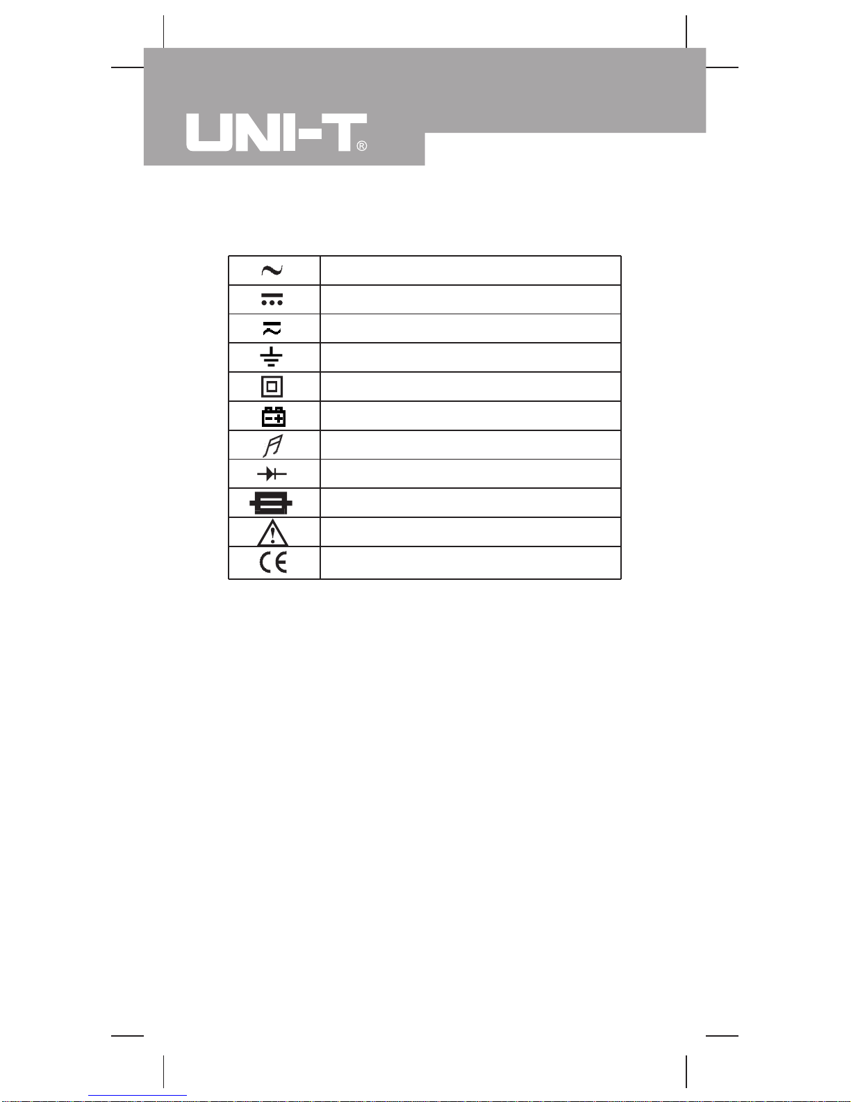
International Electrical Symbols
AC (Alternating Current).
DC (Direct Current).
AC or DC.
Grounding.
Double Insulated.
Deficiency of Built-In Battery.
Continuity Test.
Diode.
Fuse.
Warning. Refer to the Operating Manual.
Conforms to Standards of European Union.
Model UT50E: OPERATING MANUAL
8

The multimeter Structure (see figure 1)
9
( figure 1)
1LCD Display
2Data Hold Button.
3Rotary Switch
4Power
5COM Input Terminal
620A Input Terminal
7mA Input Terminal
8V oCInput Terminal
Model UT50E: OPERATING MANUAL
10
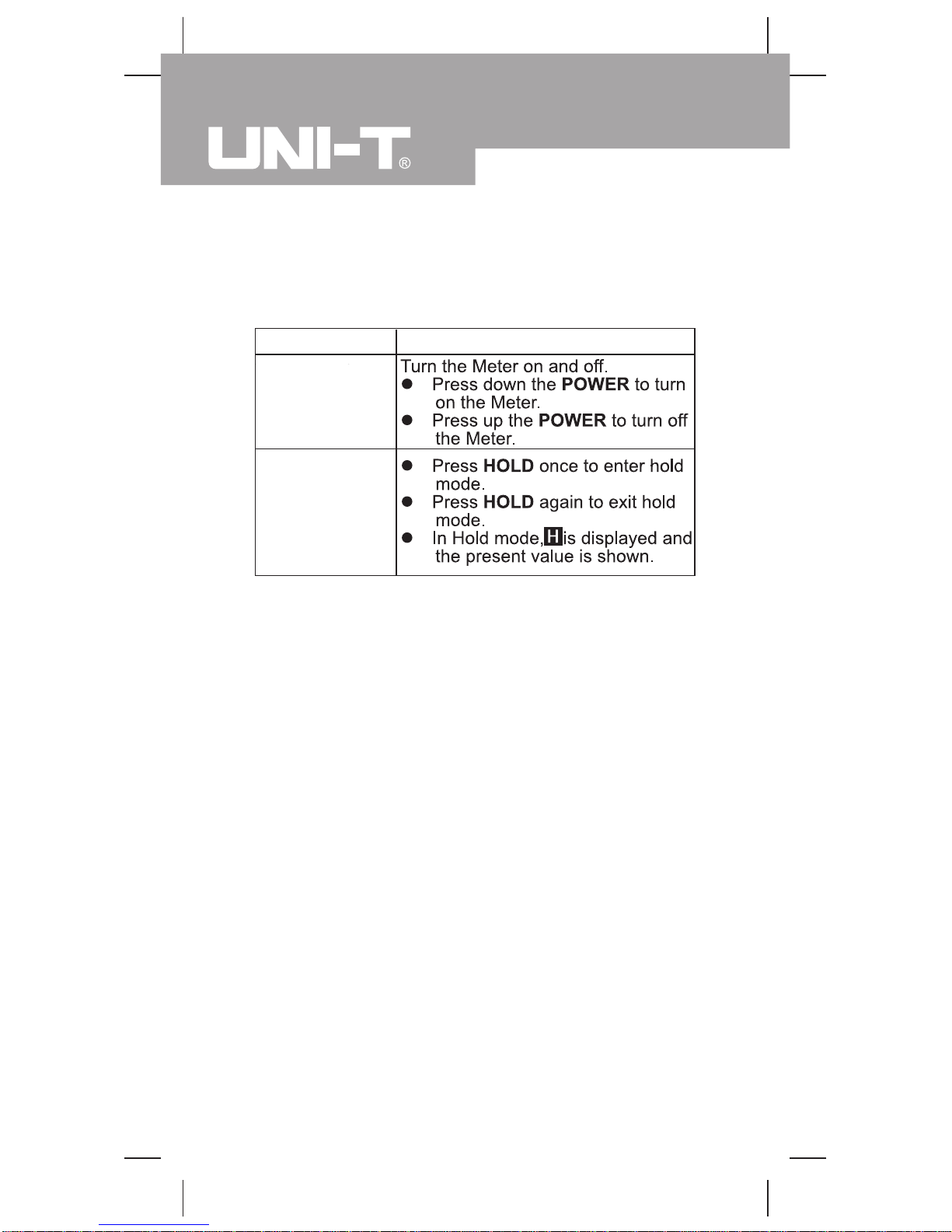
Functional Buttons
Below table indicated for information about the functional
button operations
Button Operation Performed
HOLD
(Blue Button)
POWER
(Yellow Button)
Model UT50E: OPERATING MANUAL
Table of contents
Other Unit Multimeter manuals


Popular Multimeter manuals by other brands


Gossen MetraWatt
Gossen MetraWatt METRAmax 6 operating instructions

PeakTech
PeakTech 4000 Procedure of calibration

YOKOGAWA
YOKOGAWA 90050B user manual

Gossen MetraWatt
Gossen MetraWatt METRALINE DMM16 operating instructions

Fluke
Fluke 8846A Programmer's manual

Tempo Communications
Tempo Communications MM200 instruction manual


