KEM FAU 50 User manual

2
Version
Version: FAU_M_EN_170308_E004
Manual-Version
FAU_M_EN_170308_E004
SW-Version
This manual is valid for
Main SW: V03-01.99 and higher

3
Version: FAU_M_EN_170308_E004
Index
Index
1. GENERAL ..................................................................................................................................................5
Features ......................................................................................................................................................51.1.
Operating Principle .....................................................................................................................................51.2.
2. OPERATION...............................................................................................................................................6
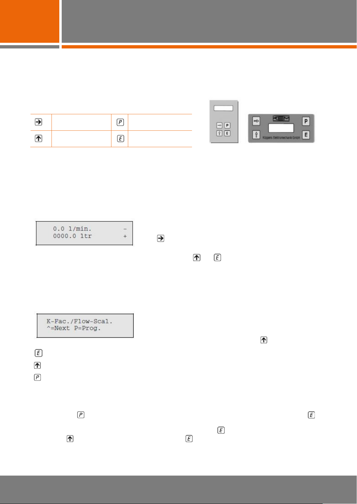
Measuring Mode .........................................................................................................................................62.1.
Parameter Levels........................................................................................................................................62.2.
Parameters .................................................................................................................................................62.3.
2.3.1. Entering Numerals ......................................................................................................................................7
2.3.2. Chosing from Pre-selections.......................................................................................................................8
3. PROGRAMMING........................................................................................................................................9
Level „K-Factor/Flow-Scaling“ ....................................................................................................................93.1.
3.1.1. K-Factor of the Flow Meter .........................................................................................................................9
3.1.2. Unit for Flow Rates ...................................................................................................................................10
3.1.3. Decimal Point Position for the Flow Rate Display (DP Flow Display) ......................................................10
3.1.4. Density of the Measuring Medium ............................................................................................................11
3.1.5. Gate Memory ............................................................................................................................................12
Parameter Level „Analogue Output Scaling“ ............................................................................................123.2.
3.2.1. Analogue Offset: Minimum Level of the Analogue Output........................................................................13
3.2.2. Scaling the Analogue Output ....................................................................................................................13
3.2.3. Response Time of the Analogue Output...................................................................................................14
Parameter level „Divider Scaling“ .............................................................................................................143.3.
3.3.1. Unit for the Divider ....................................................................................................................................14
3.3.2. Entering the Dividing Factor .....................................................................................................................14
3.3.3. Pulse Time for External Counters.............................................................................................................15
Parameter Level „Limit-Programming“......................................................................................................153.4.
3.4.1. Limit ON/OFF............................................................................................................................................16
3.4.2. Flow-Limit Max..........................................................................................................................................16
3.4.3. Hysteresis for Limit MAX...........................................................................................................................16
3.4.4. Flow-Limit MIN ..........................................................................................................................................17
3.4.5. Hysteresis for Limit MIN............................................................................................................................17
Battery Lifetime .........................................................................................................................................173.5.
4. MEASURING MODE ................................................................................................................................18
Displays in the Measuring Mode...............................................................................................................184.1.
4.1.1. Actual Flow in Unit and Measuring Frequency .........................................................................................18
4.1.2. Actual Flow in Unit and “Calmed” Measuring Frequency .........................................................................18
4.1.3. Actual Flow and Totalizer with Unit...........................................................................................................18
4.1.4. Pulse Counter and Totalizer with Unit ......................................................................................................19
4.1.5. Actual Flow and Indication of the Limit State............................................................................................19
4.1.6. Actual Flow with Unit and Analogue Output Level....................................................................................19
4.1.7. Actual Flow with uUnit and Analogue Output in Percent ..........................................................................20

4
Version: FAU_M_EN_170308_E004
Index
Operating Priciple of the Control Inputs and the Outputs .........................................................................204.2.
4.2.1. RESET Control Input (terminals 11/7) ......................................................................................................20
4.2.2. HOLD Control Input (terminals 12/7) ........................................................................................................20
4.2.3. Divider Output (terminals 13/14) ...............................................................................................................20
4.2.4. MAX Limit (terminals 15/16) .....................................................................................................................20
4.2.5. MIN Limit (terminals 17/18).......................................................................................................................21
4.2.6. Frequency Output 1:1 (terminals 18/20) ...................................................................................................21
4.2.7. Analogue Output 0/4 to 20 mA or 0/2 to 10 V (terminals 1, 2) .................................................................21
4.2.8. Forward/Bachward Output (terminals 3/4)................................................................................................21
4.2.9. Pickup Supply (terminals 3/4) ...................................................................................................................21
4.2.10. Frequency Inputs CH1 and CH2 (terminals 6/7 and 8/7) .........................................................................21
4.2.11. Supply Voltage of the FAU (terminals 9/10) .............................................................................................21
5. SPECIFICATIONS....................................................................................................................................22
Technical Data ..........................................................................................................................................225.1.
Terminals ..................................................................................................................................................235.2.
Connection Schemes................................................................................................................................245.3.

5
General
Version: FAU_M_EN_170308_E004
1. General
The FAU is a microprocessor-based unit to convert output frequencies of KEM-Amplifiers into an analogue
signal. You may chose between two signals:
•0/4 to 20 mA potential-free load independent current signal
•0/2 to 10 V potential-free voltage signal
Adjust the desired output signal via the external slide switch on the lefthand housing side (see chapter 4.2.7
and 5.2).
The FAU can scale your measuring values and display them as rate or totals. Special characteristics are:
•Short response time
•High accuracy
•Full and easy programming
Features1.1.
•LCD display
•Pulse divider
•Two limits: flow-limit MIN, flow-limit MAX.
•Potential-free limit switch outputs
•1:1 frequency output
•Detection of rotational direction
Reverse flow changes the polarity of the analogue output, resets the internal counter and activates
a switch output
•Versatile inputs for active and passive pickups
Operating Principle1.2.
An edge-controlled pulse width measurement combined with programmable time base function provides rapid
and stable measuring values. The FAU detects any alteration of the measuring value quickly and accurately.
Conversion, limits and divider are based on the measuring values. The FAU converts the input frequencies with
a resolution of 13 bit, the transmission behaviour is adjustable.
Your parameter settings and the internal counters of the FAU are maintained by a lithium battery when the is
unit turned off.

6
Operation
Version: FAU_M_EN_170308_E004
2. Operation
The FAU is operated via a front-panel touch keyboard and a two-line LCD display.
In this manual the four keys are shown as follows:
top lefthand key top righthand key
bottom lefthand key bottom righthand key
First take a look at the menu structure of the FAU. Before starting to programme real values, press the keys as
described below, observe how the display changes and compare it with the menu structure. This is how you will
easily get familiar with structure and operation of the FAU. Detailed instructions for programming will follow from
page 9 onwards.
Measuring Mode2.1.
The measuring mode automatically appears after switching FAU. The
display shows the last-selected display.
Press to scan the individual displays. A description of each display
will follow in chapter 4.
To get into the programming mode simultaneously press and . After that the first parameter level will
appear in the display.
Parameter Levels2.2.
The levels cannot be changed. They contain various parameters adaptable to your application.
1st line: Description of the parameter level
2nd line: Key functions
The sign ^ is for key
The FAU goes back to the measuring mode. The last-selected display appears.
To scan the four parameter levels.
To call up the first parameter of the present parameter level.
Parameters2.3.
Having pressed , the first parameter appears and you can change or confirm it immediately pressing . After
that the next parameter appears. Some parameters require you to enter numerals while others offer you pre-
selections to chose from. After saving the last parameter pressing , the FAU goes back to the parameter
level. Press to call up the next parameter level. Press to get back to the measuring mode.

7
Operation
Version: FAU_M_EN_170308_E004
2.3.1. Entering Numerals
1st line: Description of the present parameter
2nd line: Current value, the cursor blinks on the first decimal digit
Each pressing will move the cursor in righthand direction. When the cursor has reached the last decimal
digit, the next pressing will move the cursor back to first digit.
To scan 0 to 9 for the present digit. "0" re-appears after "9". When the cursor marks the decimal point,
will not work.
To skip a parameter or enter your settings. The FAU automatically checks whether your settings are
within the allowable range for the parameter. If you enter a value which is not within the allowable range,
the FAU will not accept it and the last-entered setting appears. Only can you continue when your settings
are within the allowable range.
Ranges for the numerical parameters
Parameter Min. Value Max. Value Remarks
K-Factor
10.00
500000.00
pulses per litre
Density
700
2000
kg per m³
Gate Time
104
3224
msec
Divider
1
90000
decimal point and unit according to
settings
Pulse Time
0.2
99.9
msec
Analog Start Value
0.000
99999.999
unit according to settings
Analog Final Value
0.001
99999.999
unit according to settings
Flow-Limit Max.
1
9999999
decimal point and unit according to
settings
Hysteresis Max.
0.1
9.9
%
Flow-Limit Min.
1
9999999
decimal point and unit according to
settings
Hysteresis Min.
0.1
9.9
%
Cut off frequency
0.4
9.9
creep quantity in Hz
Linearisation Freq.
1
9999
Hz
Linearisation Error
0.1
12.7
% (±)

8
Operation
Version: FAU_M_EN_170308_E004
2.3.2. Chosing from Pre-selections
The FAU offers you pre-selections for some parameters like units or analogue offset.
pre-selection: litres per minute
To scan the pre-selections for the present parameter. When the desired default appears, enter with .
Summary of the pre-selections
Totals Rate
kg
l/min
Grams
kg/m
Litres
ccm/m
ccm
g/min
Imp
l/h
Gal.
kg/h
lb
ccm/s
g/s
Gal/m
lb/m

9
Programming
Version: FAU_M_EN_170308_E004
3. Programming
Start programming by simultaneously pressing and . This will cause all outputs to take a defined state:
Analogue output = minimum level, limits inactive and forward/backward detection = forward.
The display shows the first parameter level where the first line describes the parameter level and the second
line informs you on the key functions. The sign "^" is for .
The FAU goes back to the measuring mode. The last-selected display appears.
Scanning the four parameter levels.
Calling up the first parameter of the present parameter level.
Level „K-Factor/Flow-Scaling“3.1.
This level is very important. Most settings which you enter here serve the calculation of further parameters of
other levels.
This level automatically appears with the first programming of the FAU.
Programming this level is a pre-condition for operating the FAU. Four
parameters have to be entered. With mass-related units there are five
parameters. Press to programme the first parameter of this level.
3.1.1. K-Factor of the Flow Meter
Each KEM Flow Meter is delivered with a calibration record, which shows the average K-factor of the flow
meter. This factor defines the number of pulses per litre over the entire measuring range. In addition, the record
contains various K-factors for certain flow values. With constant flow rates you may get a higher accuracy
chosing the K-factor which is the closest to your flow rate.
The K-factor can be entered with up to two digits following the decimal point. The decimal point position will also
apply for the actual flow display and the internal totaliser.
Example: gear flow meter type ZHM 02/1 with an average K-factor of
8,123.335 pulses per litre.
to chose the cursor position
to select 0 to 9 for the present cursor position
to enter
Entering with will call up the next parameter.

10
Programming
Version: FAU_M_EN_170308_E004
3.1.2. Unit for Flow Rates
To display measuring results in the corresponding unit, chose from pre-selections for volumetric and mass units.
In the measuring mode, the unit is only displayed with volume and mass flow.
pre-selection: litres per minute
Use to go through the pre-selections.
Totals Rate
kg
l/min
Grams
kg/m
Litres
ccm/m
ccm
g/min
Imp
l/h
Gal.
kg/h
lb
ccm/s
g/s
Gal/m
lb/m
As soon as the desired unit appears, confirm with . After that the next parameter appears.
3.1.3. Decimal Point Position for the Flow Rate Display (DP Flow Display)
You should display your measuring results with a resolution in accordance with your application. Max. three
digits after the decimal point are possible.
NOTE:
Changing the decimal point position will also affect the limits. The FAU will remind you of checking the limits and
adapting them to the present decimal point position.
Example: three digits after the decimal point are required.
Enter with , after that the next parameter appears.

11
Programming
Version: FAU_M_EN_170308_E004
3.1.4. Density of the Measuring Medium
In case you selected a volumetric unit under chapter 3.1.2, the FAU will now skip this parameter. However, with
mass-related units the FAU requires you to enter the density of the measuring medium.
KEM Flow Meters detect the volume flow. The FAU can calculate the corresponding mass flow considering the
density, provided that the density is constant.
Example: the density of the measuring medium is 1,250 kg/m3.
To chose the cursor position
To select 0 to 9 for the present cursor position
To enter
Enter with , after that the next parameter appears.
Gate time
The parameters "Gate time" and "Gate memory" enable you to adapt the temporary transmission behaviour
between frequency and analogue output to your requirements.
After the gate time has passed, the FAU calculates an average frequency for the measuring interval thereby
calming signal fluctuations.
Periodic disturbances, e. g. pressure fluctuations, will be included in the displayed values, if the gate time is too
short. You may avoid this by chosing an appropriate interval.
Example: flow variations with a period of 0.5 seconds require a gate time of ≥0.5 seconds.
You may chose a gate time from 0.10 up to 3.5 seconds in steps of 104 milliseconds. Enter your setting with
and the final parameter of the K-factor level will appear.

12
Programming
Version: FAU_M_EN_170308_E004
3.1.5. Gate Memory
This parameter determines the number of measurements which will be
considered for calculating the actual measuring frequency (the
response time of the measuring results depends on the gate time
setting). With n > 0, the FAU calculates an average value considering
the last n measurements and the actual measurement. The influence of
the actual measurement can be determined as follows:
100 % ∗1
+1
This way unique or rare disturbances are prevented from fully affecting the measuring results.Adaption of both
parameters gate time and -memory enables for any temporary behaviour whatever.
Example: The analogue output of the FAU supplies a controller with instantaneous values. You can prevent the
upper harmonic waves (caused by pumps) in the flow signal from affecting the controller by chosing an
appropriate gate time.
Quickly falling or rising flow values can cause the control unit to oscillate. Considering your controller settings,
you should therefore reduce the influence of the actual flow value on the previous measuring results by chosing
a higher value for gate memory.
Enter with , after that the FAU goes back to the K-Factor level.
From the parameter level there are three possibilities to go on:
To go through the present parameter level again in the above-mentioned order and change single
parameters if necessary.
To go back to the measuring mode. The parameter settings do now apply.
To call up the next parameter level.
Parameter Level „Analogue Output Scaling“3.2.
The main function of the FAU is to generate a current or voltage signal proportional to the input frequency.
The present parameter level contains the parameters which are necessary to scale the analogue output for 0/4
to 20 mA or 0/2 to 10 V.
Only flow values have to be entered for the analogue output. The unit (see chapter 3.1.2) and resolution (see
chapter 3.1.3) as entered in the parameter level "K-factor" (see chapter 3.1) apply.
You do not need to adjust the analogue output considering the frequency. The FAU knows the relation between
flow rate and frequency by the K-factor (see chapter 3.1.1).
Press to programme the analogue output.
Press to select the next parameter level.

13
Programming
Version: FAU_M_EN_170308_E004
3.2.1. Analogue Offset: Minimum Level of the Analogue Output
You may chose between an absolute minimum and a minimum shifted by 4 mA or 2 V.
Enter with , after that the next parameter appears.
3.2.2. Scaling the Analogue Output
You may assign the entire range of the analogue output to a working flow rate by entering a start and final value
for the analogue output.
Example: A current signal of 0/4 to 20 mA is assigned to a flow range of 1.25 to 2.74 ltr/min.
20 mA correspond to a flow rate of 2.74 l/min starting at 1.25 ltr/min.
WARNING!
The start value must be smaller than the final value. If this is not the case, a warning in the display will require
you to enter values again beginning with the start value.
Analogue start value
Enter the flow rate for 0/4 mA or 2 V.
To chose the cursor position
To select 0 to 9 for the present cursor position
To enter
Enter with , after that the analogue final value appears.
Analogue final value
Now enter the actual flow value for 20 mA or 10 V.
To chose the cursor position
To select 0 to 9 for the present cursor position
To enter
Enter with , after that the next parameter appears.

14
Programming
Version: FAU_M_EN_170308_E004
3.2.3. Response Time of the Analogue Output
The FAU can convert the measuring frequency into an analogue signal based on the incoming frequency or
based on the "calmed" frequency (see chapter 3.1.5 »Gate Time« and 3.1.6 »Gate memory«).
Example: Due to periodic flow rate fluctuations the FAU shall convert the calmed frequency calculated via
"Gate time" and "Gate memory".
Entering with will terminate the programming of this level.
There are three possibilities to go on:
To go through the present parameter level again in the above-
mentioned order and change single parameters if necessary.
To go back to the measuring mode. The parameter settings do
now apply.
To call up the next parameter level.
Parameter level „Divider Scaling“3.3.
If you intend to use an external counter, the FAU can divide the signal
of the flow meter and supply the counter with pulses proportional to the
volume flow. In this level you can programme the dividing factor and the
pulse time. Apart from that the FAU has an integrated totaliser.
Press to start programming.
3.3.1. Unit for the Divider
Keep to the unit entered for the flow rate (see chapter 3.1.2) as it determines the unit and resolution for the
dividing factor. If you selected kg/min for the flow rate, you have to enter the dividing factor in kg.
3.3.2. Entering the Dividing Factor
The max. resolution for the dividing factor is pre-determined by the K-factor setting (see chapter 3.1.1) and unit
(see chapter 3.3.1). Enter the volume with which the external counter shall count on.
With mass-related units the FAU will automatically consider the density of the measuring medium. The internal
totaliser of the FAU is not affected by this setting.
Example: the external counter shall detect the number of filled vessels, contents 1.25 litres.
To chose the cursor position
To select 0 to 9 for the present position
To enter
Enter with , after that the next parameter appears.

15
Programming
Version: FAU_M_EN_170308_E004
3.3.3. Pulse Time for External Counters
Depending on its input stage and type, the external counter may require a certain pulse time to identify the
output pulses of the FAU. With the present parameter, you can adapt the pulse time to the external counter.
This setting will not affect the integrated totaliser of the FAU.
WARNING!
The pulse time must be shorter than 50% of the period of the max. dividing frequency. Other settings may falsify
the output frequency.
Example: The external counter requires a pulse time of at least five milliseconds.
To chose the cursor position
To select 0 to 9 for the present cursor position
To enter
Example: The flow rate is 4,000 ccm/min and the external counter shall count on one unit with each ccm. The
required pulse time t(p) can be calculated as follows:
4000 ccm/
60 s/ min∗1 =66,67 => ()= 14.99 ∗50 %
100 % = 7.5 ()
Entering with will terminate programming for the divider. The display
is showing the present parameter level
There are three possibilities to continue:
to go through the present parameter level again in the above-mentioned order and change single
parameters if necessary.
to go back to the measuring mode. The parameter settings do now apply.
to call up the next parameter level.
Parameter Level „Limit-Programming“3.4.
The FAU has two separate switch outputs for real-time flow monitoring.
You can determine a maximum and minimum. Any bypassing of these
limits will activate the corresponding output.
WARNING!
The minimum must be smaller than the maximum. If this is not the case, a warning will require you to re-enter
the limits starting with the maximum.

16
Programming
Version: FAU_M_EN_170308_E004
3.4.1. Limit ON/OFF
If you do not need the limit values for your measuring task or only occasionally, you may deactivate them.
select ON/OFF
confirm input
The next screen appears:
continue with limit programming
terminate limit programming
If you have selected for »Exit«, you can press to go to the next main level aufrufen.
If you have selected für »Programming«, the next parameter appears. You can continue with programming
even if you have selected the "OFF" state; in this case, the settings are not activated in the later measuring
operation, but can be activated by selecting the "ON" state and then ending the programming as described
above.
3.4.2. Flow-Limit Max.
Now enter the max. limit. If the flow rate exceeds this limit, the switch output MAX will be activated. Enter the
max limit keeping to the unit and resolution selected under chapter 3.1.2 and 3.1.3.
Example: the volume flow must not exceed 2.854 litres per minute.
to chose the cursor position
to select 0 to 9 for the present cursor position
to enter
Enter with and continue with the hysteresis for the max. limit.
3.4.3. Hysteresis for Limit MAX
If the volume or mass flow is unstable, the switch output may start to "scatter" when the flow rate approaches
the limit. To avoid this enter a hysteresis which is slightly higher than the percentual flow variation within the
max. limit range.
Example: with flow variations of 3.5 % in the upper range, the hysteresis should be approx. 3.8 %.
to chose the cursor position
to select 0 to 9 for the present cursor position
to enter
Enter with , after that "Flow-Limit MIN" appears in the display.

17
Programming
Version: FAU_M_EN_170308_E004
3.4.4. Flow-Limit MIN
Now enter the min. limit. If the flow rate bypasses this limit, the switch output MIN will be activated. Enter the
min limit keeping to the unit and resolution selected under 3.1.2 and 3.1.3 .
Example: the volume flow must not bypass 1.185 litres per minute.
to chose the cursor position
to select 0 to 9 for the present cursor position
to enter
Enter with and continue with the hysteresis for the min limit.
3.4.5. Hysteresis for Limit MIN
If the volume or mass flow is unstable, the switch output may start to "scatter" when the flow rate approaches
the limit. To avoid this enter a hysteresis which is slightly higher than the percentual flow variation within the
min. limit range.
Example: with flow variations of 7.0 % in the lower range, the hysteresis should be approx. 7.2 %.
to chose the cursor position
to select 0 to 9 for the present position
to enter
Entering with will terminate programming. Press to get back to the measuring mode.
Battery Lifetime3.5.
The FAU has a battery to maintain all parameter settings and counts when the FAU is turned off. With normal
operation (8 h per day) the battery will last for at least ten years.
When the battery becomes low or fails, the FAU will inform you on this
with the following display after switching on.All parameters are lost now.
Press to remove this display.
The FAU will go to the first parameter level "K-Factor" (see chapter 3.1.1). After re-programming you can go on
operating.
WARNING!
If the FAU was turned off now, all parameters would be lost again. This would require a new programming of the
FAU each time it had been turned off. You should therefore send the FAU back to KEM to have the battery
replaced.

18
Measuring Mode
Version: FAU_M_EN_170308_E004
4. Measuring Mode
The FAU offers you versatile possibilities of evaluating your measuring results:
•Various possibilities of displaying and monitoring the measuring results
•Analogue output 0/4 to 20 mA or 0/2 to 10 V
•Frequency inputs and control outputs
Displays in the Measuring Mode4.1.
Press to go through the displays. When the desired display appears, stop pressing .
The display is maintained automatically even if you leave the measuring mode or turn off the FAU.
4.1.1. Actual Flow in Unit and Measuring Frequency
1st line: scaled flow rate with unit and
state limit MAX (+ = exceeded, – = not exceeded)
2nd line: direct input frequency,
state limit MIN (+ = bypassing, – = no bypassing)
4.1.2. Actual Flow in Unit and “Calmed” Measuring Frequency
The FAU derives the calmed measuring frequency from the incoming measuring frequency considering the
settings for "Gate time" (see chapter 3.1.5) and "Gate memory" (see chapter 3.1.6).
1st line: scaled flow rate with unit and
state limit MAX (+ = exceeded, – = not exceeded)
2nd line: calmed input frequency,
state limit MIN (+ = bypassing, – = no bypassing)
4.1.3. Actual Flow and Totalizer with Unit
The FAU has a totaliser to count incoming pulses according to the settings for the K-factor (see chapter 3.1.1).
Pressing while this display is selected will reset the totaliser. A reset can also be realized with the control
input "RESET".
1st line: scaled flow rate with unit and
state limit MAX (+ = bypassing, – = no bypassing)
2nd line: scaled totaliser with unit and
state Limit MIN (+ = bypassing, – = no bypassing)
The totaliser counts up and down with rotational direction "forward" and "backwards" respectively.

19
Measuring Mode
Version: FAU_M_EN_170308_E004
4.1.4. Pulse Counter and Totalizer with Unit
This display shows total pulses and incoming pulses of the flow meter. Pressing while this display is
selected will reset the totaliser. A reset can also be realized with the control input "RESET".
1st line: incoming pulses unscaled and state Limit MAX
(+ = exceeded, – = not exceeded)
2nd line: scaled totaliser with Unit and state Limit MIN
(+ = bypassing, – = no bypassing
Both counters count up and down with rotational direction "forward" and "backwards" respectively.
4.1.5. Actual Flow and Indication of the Limit State
Example: A flow range of 0.6 up to 1.5 litres per minute must be maintained.
1st line: scaled flow rate with unit
2nd line: state limit MIN/MAX
No Limit = no bypassing
1st line: scaled flow rate with unit
2nd line: state limit MIN
Limit MIN = limit bypassed
1st line: scaled flow rate with unit
2nd line: state limit MAX
Limit MAX = limit exceeded
4.1.6. Actual Flow with Unit and Analogue Output Level
The sign "I" shows the present level of the analogue output. The scale (broken line) in the second line
represents an output signal from 0 to 100 %.
The polarity of the analogue signal changes with rotational direction "backwards".
1st line: scaled flow rate with unit
2nd line: the broken line is for 0 to 100 %,
“I” shows the actual level of the output
If "<" appears at the beginning of the broken line, the output has bypassed 1 % of the maximum.
If ">" appears at the end of the line, the output has exceeded 99 % of the maximum.

20
Measuring Mode
Version: FAU_M_EN_170308_E004
4.1.7. Actual Flow with uUnit and Analogue Output in Percent
1st line: scaled flow rate with unit
2nd line: analogue output in percent
Operating Priciple of the Control Inputs and the Outputs4.2.
The FAU has two frequency inputs and two control inputs which can influence different outputs and the internal
counters. The control outputs are low-active, they have to be connected with the potential reference of the
pickup supply. All outputs except for the analogue output are open-collector outputs.
4.2.1. RESET Control Input (terminals 11/7)
Activating this input will reset the internal pulse counter and totaliser to zero. Furthermore there is no
incrementation or decrementation of the counters.
This function is also available via in the displays under chapter 4.1.3 and 4.1.4.
Examples: changing of the measuring medium or a change of shifts.
4.2.2. HOLD Control Input (terminals 12/7)
The following happens while this input is active:
•The FAU maintains the present analogue level which is available at the analogue output.
•Reverse flow detection is disabled. The output holds the last-detected direction.
•Totaliser and pulse counter remain on their present count.
•Limit MIN and MAX are inactive
"HOLD active" in the 2nd line of the display indicates the HOLD input is active. The display of the actual flow is
not affected by the HOLD input.
The HOLD function is useful when you do not want to evaluate the flow rate of start portions or while the flow
meters are purged.
4.2.3. Divider Output (terminals 13/14)
This output supplies external counters with a divided frequency (see chapter 3.3). The output sends an output
pulse after the pre-selected volume has passed through the flow meter (see chapter 3.3.2). The pulse time (see
chapter 3.3.3) is adjustable). After that the transistor is blocking again.
4.2.4. MAX Limit (terminals 15/16)
The open-collector track of this output conducts, when the actual flow exceeds the MAX limit (see chapter
3.4.1).The output is blocked ("OC-track blocked"), when the actual flow bypasses the value for MIN limit less
hysteresis (see chapter 3.4.2).
Table of contents