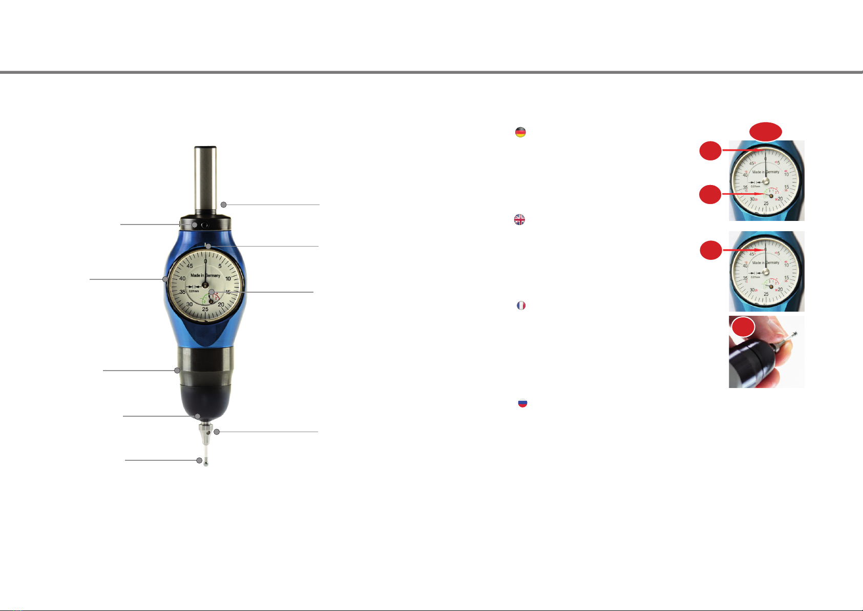
Die Bezugslänge des 3D-Tasters auf einem Voreinstellgerät
ermitteln. Dabei sind 1,5 mm für den Messweg des 3D-Tas-
ters zu subtrahieren.
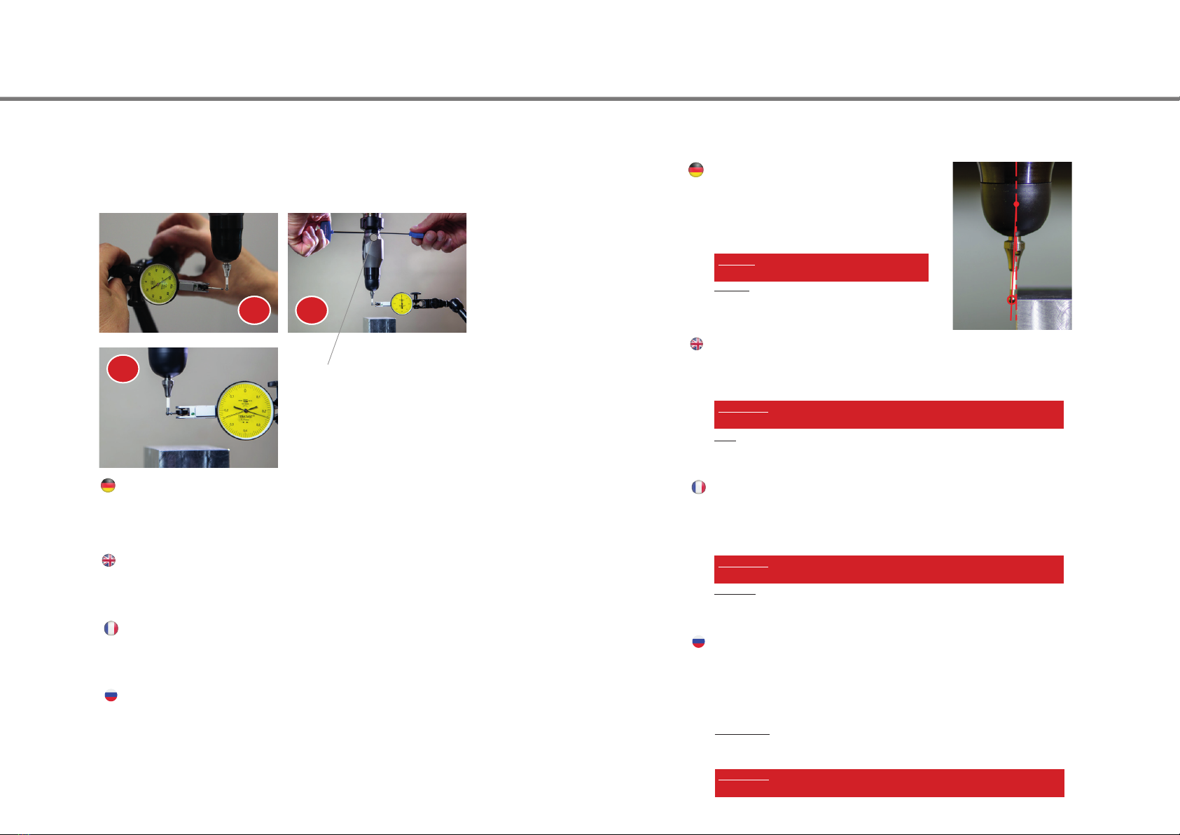
Den Taster in die Spindel einsetzen. Kühlmittelzufuhr und
Spindel abschalten.
Bitte exakt senkrecht zum Werkstück antasten, sonst könn-
ten Messfehler entstehen.
Mit dem Taster vorsichtig der Oberäche des Werkstücks
nähern, bis sich der große Zeiger zu bewegen beginnt. Dann
so lange weiter tasten bis beide Zeiger (klein und groß) exakt
„0“ anzeigen.
Die Spindel steht nun in Höhe der ermittelten Bezugslänge
über dem Werkstück.
1.
2.
3.
4.
5.
Hinweis:
Ein Überfahren der Werkstückkante um bis zu 1,5 mm (klei-
ner Zeiger im roten Bereich) ist problemlos. Nach 1,5 mm
kommen mechanische Endanschläge, welche den Tasteinsatz
zum Bruch an der Sollbruchstelle führen um den 3D-Taster zu
schützen.
Determine the 3D-Tester reference length with a pre-setting device. Please note that 1,5 mm must be
subtracted from this length.
Insert the 3D-Tester into the spindle. Cut-o the coolant supply and turn o the spindle.
Please make sure that the probing is exactly perpendicular. Otherwise, measurement failures may
occur.
Move the 3D-Tester carefully towards the work piece surface until the large indicator starts moving.
Continue until both indicators (large and small) show exactly „0“.
Now, the spindle is located at the height of the determined reference length above the work piece.
1.
2.
3.
4.
5.
Note:
It is not a problem to overrun the edge of the work piece up to 1.5 mm (small pointer in the red area).
After 1.5 mm, there are mechanical limit stops which lead to the probe tip halting at the predetermined
breaking point in order to protect the 3D-Tester.
La longueur de référence du palpeur 3D est à élaborer avec un appareil de préréglage. Sous-
traire 1,5 mm pour la voie de mesure du palpeur 3D.
Incorporer le palpeur dans la broche. Mettre l’approvisionnement en uide de refroidissement
et la broche hors marche.
Veuillez s’il vous plaît veiller à une position verticale exacte à l’outil an de contrecarrer les
erreurs de mesure.
Approcher prudemment la surface de l’outil avec le palpeur jusqu’à ce que la grande aiguille
commence à se déplacer. Avancer ensuite en tâtonnant jusqu’à ce que les deux aiguilles (petite
et grande) se trouve exactement sur la position « 0 ».
La broche se trouve alors au-dessus de l’outil à la hauteur de la longueur de référence.
1.
2.
3.
4.
5.
Indication:
Un passage de 1,5 mm du bord de l’outil (petite aiguille dans la zone rouge) n’est pas problémati-
que. Des coups naux mécaniques apparaissent après 1,5 mm, ces derniers peuvent provoquer
une coupure au point de choc prévisionnel an de protéger le palpeur 3D.
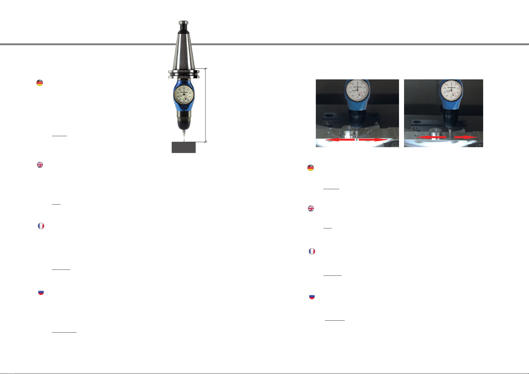
Bezugslänge
reference length / Longueur de référence
abzlg. 1,5 mm / less 1,5 mm / moins de 1,5 mm
Antasten axial
Axial probing
Palpage axial
Аксиальное измерение
Den Taster in die Spindel einsetzen. Kühlmittelzufuhr und Spindel abschalten.
Mit dem Taster vorsichtig der Werkstückkante nähern, bis sich der große Zeiger zu be-
wegen beginnt. Dann so lange weiter tasten bis die gewünschte Position erreicht ist.
Nun können Sie die Parallelität entlang Ihrer Werkstückkante abfahren. Dies ist in allen
Achsen X, Y oder Z möglich.
Hinweis: Ein Überfahren der Werkstückkante um bis zu 1,5 mm (kleiner Zeiger im roten
Bereich) ist problemlos. Nach 1,5 mm kommen mechanische Endanschläge, welche den
Tasteinsatz zum Bruch an der Sollbruchstelle führen, um den 3D-Taster zu schützen.
Insert the 3D-Tester into the spindle. Cut-o the coolant supply and turn o the spindle.
Move the 3D-Tester carefully to the edge of the work piece until the large indicator starts
moving. Continue until your requested position is reached.
Now you can start moving along the edge of the work piece to check parallelism in all axis
X, Y or Z.
1.
2.
3.
Note:
It is not a problem to overpass the edge of the work piece up to 1.5 mm (small pointer in the red
area). After 1.5 mm, there are mechanical limit stops which lead to the probe tip halting at the
predetermined breaking point to protect the 3D-Tester.
Indication:
Un passage de 1,5 mm du bord de l’outil (petite aiguille dans la zone rouge) n’est pas pro-
blématique. Des coups naux mécaniques apparaissent après 1,5 mm, ces derniers peu-
vent provoquer une coupure au point de choc prévisionnel an de protéger le palpeur 3D.
1.
2.
3.
Insérez le palpeur 3D dans la broche. Arrêtez le uide de refroidissement.
Approcher avec précaution le bord de la pièce avec le palpeur 3D jusqu‘à ce que la gran-
de aiguille commence à se déplacer. Continuez jusqu‘à ce que la position désirée est
atteinte.
Maintenant, vous pouvez laisser le parallélisme le long de votre arête de la pièce. Ceci
est possible dans tous les axes X, Y, ou Z.
1.
2.
3.
X / Y Z
Определите предварительную длину установки 3D-тестера. Обратите внимание, что
для определения базовой длины, необходимо вычесть 1,5 мм.
Установите 3D-тестер в шпиндель. Остановите подвод СОЖ и вращение шпинделя.
Пожалуйста, убедитесь, что измерение проводится строго перпендикулярно. В противном
случае, может возникнуть погрешность измерения.
Аккуратно переместите 3D- тестер к краю заготовки, пока большой индикатор не начнет
двигаться. Продолжайте, пока оба индикатора (большой и маленький) установятся на «0».
Теперь, шпиндель расположен на высоте определено выше опорной длины заготовки.
1.
2.
3.
4.
5.
Примечание:
Допускается пересечение кромки обрабатываемой детали до 1,5 мм (маленький указатель в
красной зоне). После 1.5мм, есть механические упоры, которые приводят к остановке щупа
в заданной критической точке для защиты 3D-тестера.
Внимание:
Ничего страшного если Вы превзойдете край обрабатываемого изделия на 1,5 мм
(маленький указатель в красной зоне). Через 1,5мм расположены механические
ограничители хода, которые приводят к остановке измерительного наконечника в
заданной точке останова для защиты 3D тестера.
Установите зD тестер в шпиндель. Прервите подачу СОЖ и выключите шпиндель.
Осторожно продвигайте 3D тестер к краю обрабатываемого изделия, пока
большой индикатор не прийдет в движение. Продолжайте, пока не достигните
необходимого положения
Теперь можно начинать движение вдоль края обрабатываемого изделия для
проверки параллельности всех осей: X, Y или Z.
1.
2.
3.
Paralleles Abfahren X/Y/Z
Parallel running X/Y/Z
Palpage en parallèle X/Y/Z
Параллельное перемещение по X/Y/Z