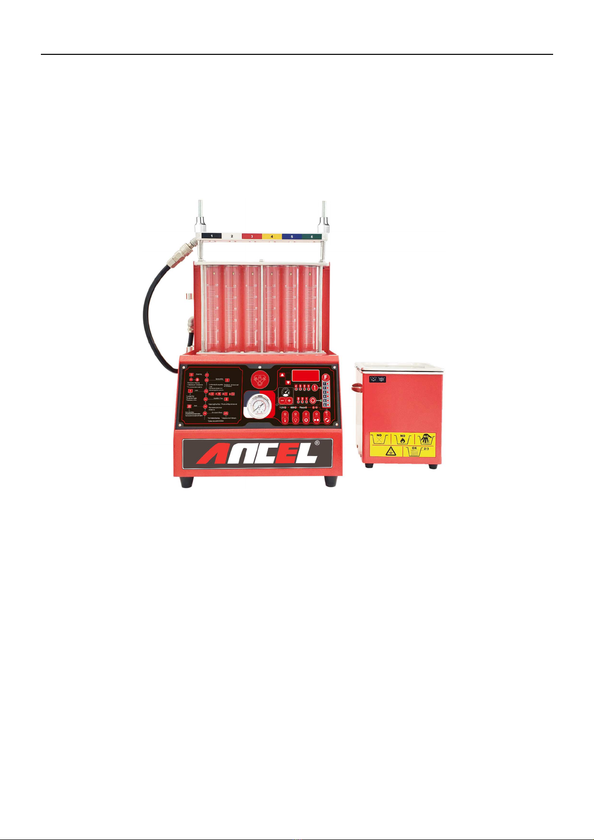
AJ600 GDI Piezo Injector Cleaner & Tester
6
4) Wi e the table to of the machine with a soft dry cloth.
5) To avoid volatilization, all the test solution in the fuel tank should be discharged. If it can be used again, store it
in a safe lace. If it is dirty and cannot be used any more, dis ose it according to relevant regulations.
V. Operation
Important reminder: Before the test o eration, Press the key to choose the correct injector ty e for ro er
o erating. When test the Piezo injector, MAKE SURE TO USE THE “Piezo Cable” FOR TESTING. There will
be an E1 error on the screen for wrong cable, and an E2 error when connect non-Piezo injectors on Piezo test mode.
Safety reminder: During the testing or cleaning rocess of the iezoelectric fuel injector, IT IS FORBIDDEN TO
DIRECTLY PLUG AND UNPLUG THE PULSE SIGNAL LINE WITHOUT STOPPING THE OPERATION. Be
sure to sto running first!
5.1 esistance Test
1) Connect one end of the resistance measurement line to the interface on the right side of the device, and the other
end to the two electrodes of the fuel injector.
2) Start the machine, and ress the key until the light of the
key is ON. Press t
he RUN key
and the
resistance value will be dis layed on the screen.
3) If needed, measure several times to confirm the measured value.
4) After the measurement is com leted, remove the fuel injector and the resistance measurement line.
5.2 Ultrasonic Cleaning
Injector Cleaner takes advantage of the enetrability and cavitation im act wave caused by ultrasonic wave traveling
through the medium to rovide owerful cleaning on objects with com lex sha es, cavities and ores, so that the
stubborn carbon de osits can be removed from the injectors.
Procedures
1) Place the injector/ um which has gone through surface cleaning in the launder.
2) Add enough injector detergent into ultrasonic cleaner so that the liquid level is about 20mm above the needle valve
of injectors / whole um .
3) Plug the ulse signal wire to injector / um res ectively.
4) Select ultrasonic cleaning function and then set the time.
5) Press RUN key to start the rocedure.
6) When the time is u , it will sto automatically as the bee er rings.
7) Take the injector / um out of the launder and wi e them with a dry soft cloth. Get ready for next o eration.
Note:
1) It is strictly forbidden to o en the ultrasonic system under the circumstances that cleaning agent has not been added
into the ultrasonic cleaning ool. Otherwise, the ultrasonic equi ment may be damaged easily.
2) It is strictly rohibited to immerse the ulse signal line connector along with the injector into the ultrasonic ool
for cleaning. Otherwise, the ulse signal line connector can be damaged easily.
5.3 Uniformity/Sprayability Test
Uniformity test is to find out the difference of the injectors injecting at the same working condition. This test can
indicate the com rehensive influences on the injector caused by electrical nature, bore variation and clogging. S ray
ability test is to ins ect the s raying erformance by observing the injectors.
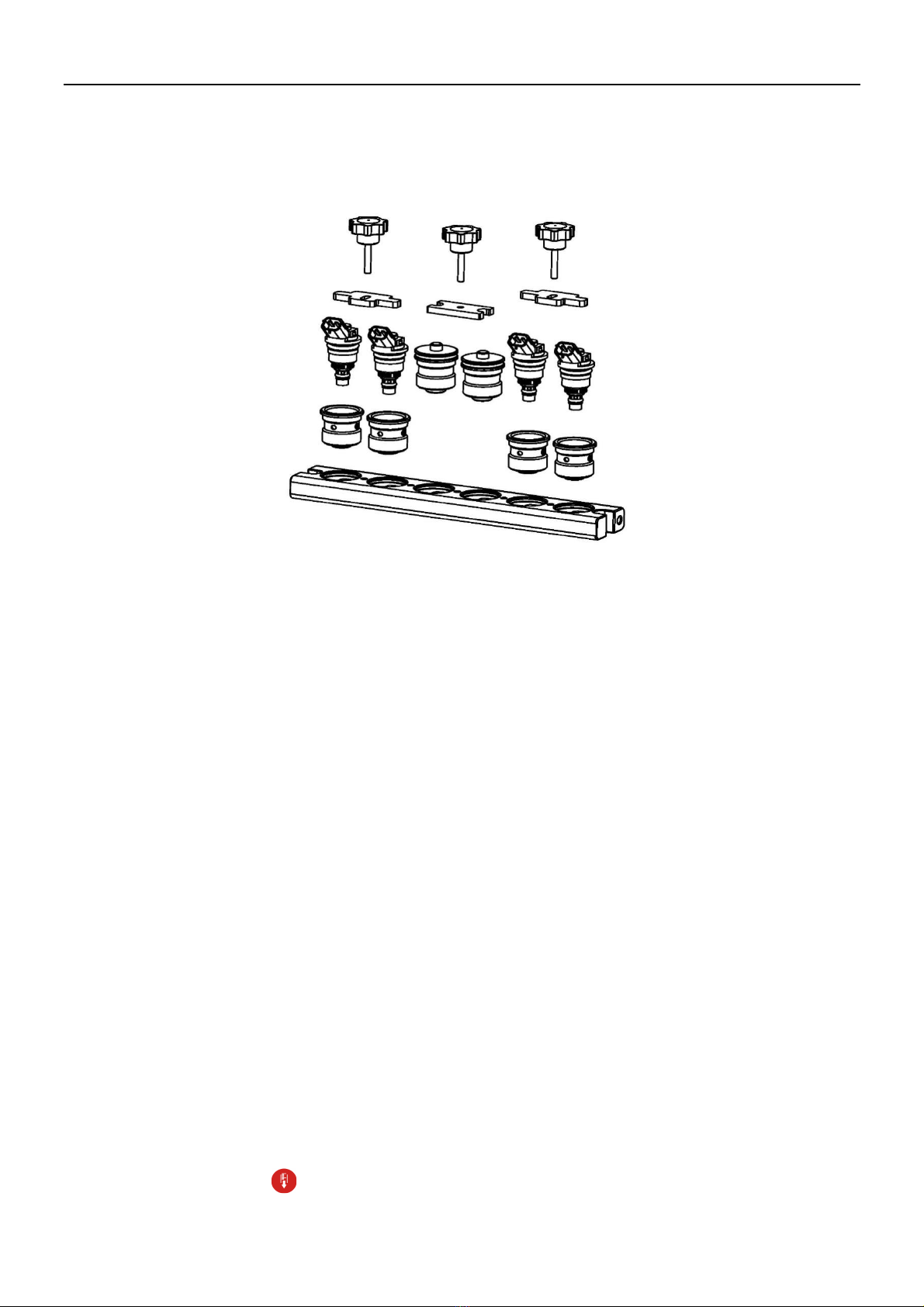
Installing and testing procedures for injectors
1) Choose a ro er ada tor according to the injector ty e and mount it to the fuel se arator.
2) Install the injectors in forward direction (A ly a little lubricating grease on the O-ring.)
3) Install the fuel se arator with injector onto the late of the test tube.
4) Connect the injector ulse signal wire.
5) Before doing this test, ress DRAIN icon to drain the test liquid from the measuring cu if there is any.