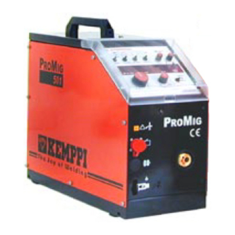
Kemppi HF 10E User manual

Operating manual
操作手册
EN
ZH
HF
10E, 10P


OPERATING MANUAL
English

EN
CONTENTS
1. Introduction................................................................................................. 3
1.1 General ....................................................................................................................................... 3
1.2 About HF wire feeder............................................................................................................ 3
2. Installation.................................................................................................... 4
2.1 Before use.................................................................................................................................. 4
2.2 Power source connection.................................................................................................... 4
2.3 Shielding gas connection.................................................................................................... 4
2.4 Welding gun connection..................................................................................................... 5
3. Using the machine ..................................................................................... 6
3.1 Machine introduction........................................................................................................... 6
3.1.1 Wire feeder front and side view...................................................................................... 6
3.1.2 Wire feed mechanism...................................................................................................... 7
3.2 Installing ller wire................................................................................................................. 7
3.2.1 Mounting the wire spool................................................................................................. 7
3.2.2 Feeding the welding wire ............................................................................................... 7
3.3 Setting the pressure of the feed rolls.............................................................................. 8
3.4 Setting the spool brake force ............................................................................................ 8
3.5 Changing the feed rolls........................................................................................................ 8
4. Controlling welding functions ................................................................ 9
4.1 Control panel functions in basic operation.................................................................. 9
4.2 Control panel functions in automatic operation........................................................ 9
5. Maintenance.............................................................................................. 10
5.1 Regular maintenance..........................................................................................................10
5.2 Disposal of the machine ....................................................................................................10
6. Technical data............................................................................................ 10
7. Ordering codes.......................................................................................... 11
HF 10E, 10P
2

EN
1. INTRODUCTION
1.1 General
Congratulations on choosing the Kemppi HF wire feeder. Used correctly, Kemppi products
can signicantly increase the productivity of your welding, and provide years of economical
service.
This operating manual contains important information on the use, maintenance and safety of
your Kemppi product. The technical specications of the device can be found at the end of the
manual.
Please read the manual carefully before using the equipment for the rst time. For your
own safety and that of your working environment, pay particular attention to the safety
instructions in the manual.
For more information on Kemppi products, contact Kemppi Oy, consult an authorised Kemppi
dealer, or visit the Kemppi web site at www.kemppi.com.
The specications presented in this manual are subject to change without prior notice.
NOTE! Items in the manual that require particular attention in order to minimise damage and
personal harm are indicated with this symbol. Read these sections carefully and follow their
instructions.
Disclaimer
While every eort has been made to ensure that the information contained in this guide
is accurate and complete, no liability can be accepted for any errors or omissions. Kemppi
reserves the right to change the specication of the product described at any time without
prior notice. Do not copy, record, reproduce or transmit the contents of this guide without
prior permission from Kemppi.
1.2 About HF wire feeder
Kemppi’s HF wire feeder in designed to be used especially with Kemppi’s HiArc power sources.
They are inverter MIG/MAG welding power sources to be used in 3-phase mains power
supply. There are two power classes available, the 350-ampere version (HiArc 350A), and the
500-ampere version (HiArc 500A).
The HiArc power sources are equipped with automatic adjustment features. This means that
you can use either manual mode or automatic mode when adjusting the welding parameters.
In automatic mode, the HiArc chooses automatically the suitable preset welding parameters
according to your wire and gas selections.
Welding gun connection:
• HF 10E is equipped with a Euro connector
• HF 10P is equipped with a Panasonic connector
Enjoy welding with your Kemppi product!
3
© Kemppi Oy / 1217

EN
2. INSTALLATION
2.1 Before use
The product is packed in cartons designed specically for them. However, always make sure
before use that the products have not been damaged during transportation.
Check also that you have received the components you ordered and the instruction manuals
needed. Product packaging material is recyclable.
NOTE! When moving the welding machine, always lift it from the handle, never pull it from the
welding gun or other cables.
Operating environment
This machine is suitable for both indoor and outdoor use. Always make sure that the air ow in
the machine is unrestricted. The recommended operating temperature range is -20…+40 °C.
Please read also the safety instructions concerning the operating environment earlier in this
manual.
2.2 Power source connection
The HF wire feeder is recommended to be used with the Kemppi HiArc power source, but it
can be used with other power source brands as well.
To connect the wire feeder to the power source, do the following:
1. Attach the wire feeder interconnection cable to the plus connector of the power source.
2. Attach the wire feeder control cable to the control connector of the power source.
NOTE! Normally the wire feeder should be connected to the plus pole. However, with some ller
wires and shielding gases, you should connect the feeder to the minus pole, and the earth return
cable to the plus pole.
2.3 Shielding gas connection
The shielding gas hose is xed to the magnet valve of the HF wire feeder.
Connect the other end of the gas hose to a gas cylinder’s control valve or to the shielding gas
distribution network at your worksite.
The thickness of the parent material, joint type and welding power dene the required
shielding gas ow rate.
NOTE! Make sure that you are using the correct type of shielding gas for the welding application.
To connect the shielding gas hose to a suitable regulator for MIG/MAG welding
1. Connect the shielding gas hose to the gas cylinder’s control valve and tighten the
connector (connector is not supplied in the package).
2. Adjust the shielding gas ow rate with the control valve screw.
3. Always close the cylinder valve after use.
HF 10E, 10P
4

EN
Parts of the gas ow regulator
5
2
4
7
16
3
1. Gas bottle valve
2. Flow regulation screw
3. Connecting nut
4. Hose tail
5. Hose tail nut
6. Gas bottle pressure gauge
7. Shielding gas ow meter
2.4 Welding gun connection
HF 10E
Connect the welding gun cable to the Euro adapter socket located on the front of the machine
and hand tighten only. Do not over tighten the collar.
HF 10P
Attach the gun current cable to the connector on the wire feeder, and tighten the Allen screw.
Attach the 2-pin connector of the control wire to the wire feeder connection. Connect the
shielding gas hose to the wire feeder, and tighten the connection.
The welding gun leads the ller wire, shielding gas and electric current to the weld piece.
When you press the welding gun trigger, shielding gas will ow and ller wire will begin to
feed.
5
© Kemppi Oy / 1217

EN
3. USING THE MACHINE
3.1 Machine introduction
3.1.1 Wire feeder front and side view
1
2
3
47
8
9
1
2
3
47
65
8
9
10 1
2
3
4
6
5
8
9
1
2
3
47
65
8
9
10
1. 5.
6.
7.
2.
3.
4.
HF 10E front
1. EURO connector for welding gun
2. Amperage/WFS control knob
3. Voltage control knob
4. Wire inch button
HF 10P front
5. Panasonic connector for welding gun
6. Connector for trigger wires of gun
7. Gas connector for gun
8.
9.
10.
11.
Side
8. Wire feed mechanism
9. Wire spool hub
10. Shielding gas connector
11. Spool locking lever
HF 10E, 10P
6

EN
3.1.2 Wire feed mechanism
2.
3.
4.
6.
5.
1.
1. Pressure arm
2. Front wire conduit
3. Wire drive roll
4. Straightening rolls adjustment knob
5. Straightening rolls
6. Top feed roll holder
3.2 Installing ller wire
With HF you can use 0.8 to 1.6 mm ller wires. The wire spool can be up to 300 mm in diametre
and 105 mm in width.
When choosing the ller wire, remember that the wire must have approHiArcately the same
melting point as the base material to be welded.
NOTE! When changing the ller wire, always check that the feed rolls, their groove shape and size
and the wire liner inside the welding cable are suitable for the wire you are using. Also check that
you are using right polarity for the ller wire.
3.2.1 Mounting the wire spool
To mount the wire spool:
1. Turn the locking lever to open position.
2. Check the rotating direction of the wire spool and push the spool into its place so that it
rotates in the right direction.
3. Turn the locking lever to closed position and tighten the securing screw.
3.2.2 Feeding the welding wire
NOTE! Remember to remove the sharp cut tip of the ller wire before loading the wire to the
welding gun, so preventing damage to the liner inside the welding gun cable. It will also improve
feed quality and increase the service life of your gun liner.
NOTE! When feeding the welding wire into the gun, be sure that you are not pointing the gun at
anyone and that there isn’t anything in front of the gun.
7
© Kemppi Oy / 1217

EN
To feed the wire from the spool to the welding gun:
1. Open the pressure arm of the wire feed mechanism and lift the top roll holder to its up
position.
2. Draw some loose wire from the spool and push it through the straightening rolls at
the back of the mechanism. You can loosen the bottom straightening roll with the
adjustment screw located below it.
3. Adjust the straightening rolls so that the wire is rmly fed into the drive roll.
4. Push the wire over the feed roll groove and through the front wire guide until it comes
out from the Euro connector by about 150mm.
5. Replace the top feed roll holder over the wire and close the pressure arm.
6. Cut away any deformed wire section and dress the sharp wire tip as described above.
7. Connect the welding gun and tighten the collar.
8. Press the Wire inch button and allow the ller wire to feed through the gun cable to the
contact tip.
3.3 Setting the pressure of the feed rolls
To make ller wire run smoothly into the wire liner and to the welding gun you can adjust the
pressure of the feed rolls of the wire feed mechanism.
To increase the pressure applied to the welding ller wire, turn the black pressure
adjustment knob in a clockwise direction.
To decrease the pressure applied to the welding ller wire, turn the black pressure
adjustment knob in an anti-clockwise direction.
There is a graduation scale marked on the arm of the adjustment knob. The more pressure
applied, the greater the number of graduation marks visible.
For hard steel and stainless steel ller wires, make sure there is sucient pressure applied, so
avoiding ller wire slippage in the feed rolls.
NOTE! Too much pressure may atten the ller wire, damage its coating, cause friction and
excessive wear to drive roll bearings and therefore reduced life.
3.4 Setting the spool brake force
To prevent the ller wire from uncoiling on overrun following use at high feed speeds, you can
change the brake force of the welding spool.
The spool brake adjustment screw is located inside the spool hub. To adjust the brake force,
unscrew the spool locking mechanism on the tip of the wire spool hub.
To increase the force turn the screw clockwise, and to decrease it, by turn the screw
anticlockwise.
NOTE! Do not over tighten, and reduce the pressure for light ller wire types.
3.5 Changing the feed rolls
The drive roll has two dierent sized grooves in it. You can choose which groove to use by
opening the drive roll securing screw and turning the drive roll other way round. The size of
the groove currently in use is facing outward.
HF 10E, 10P
8
EN
4. CONTROLLING WELDING FUNCTIONS
1
2
3
4
6
5
8
9
1
2
3
47
65
8
9
10
WIRE INCH
MANUAL
AUTOMATIC
个别 一元化
In the HF control panel you can adjust the welding current and welding voltage (V). The
functions of these adjustments depend on whether you are using the power source in
automatic or basic operating mode.
With the Wire inch button you can feed the ller wire into the welding gun.
4.1 Control panel functions in basic operation
If you are using the power source in basic operating mode without automatic functions, the
control knobs have the following functions:
With the amperage knob (A) you can adjust the welding current and the wire feed speed.
The wire feed speed increases with the amperage level.
With the voltage knob (V) you can adjust the welding voltage level. The voltage level
determines the arc length.
4.2 Control panel functions in automatic operation
If you are using the power source in automatic operating mode, the power source takes care
of adjusting the wire feed speed and the welding voltage according to the welding power you
adjust.
In automatic operating mode the control knobs have the following functions:
With the amperage knob (A) you can set the welding power. The welding current, wire feed
speed and the welding voltage are adjusted automatically according to this setting.
With the voltage knob (V) you can make ne adjustments to the welding voltage. The
middle position of the knob is the default value.
9
© Kemppi Oy / 1217

EN
5. MAINTENANCE
5.1 Regular maintenance
Check regularly the electrical connections of the machine. Clean any oxidised connections,
and tighten the loosened cable connections. Remove regularly any dust and lings from the
wire conduit tip and feed rolls.
Do not try to open the motor and the reductor of the machine for repair or lubrication. They
do not need maintenance.
NOTE! Remember that the machine may be repaired only by an electrical contractor or installer
authorised to perform such operations.
5.2 Disposal of the machine
Do not dispose of electrical equipment with normal waste!
In observance of European Directive 2002/96/EC on waste electrical and electronic
equipment, and its implementation in accordance with national law, electrical equipment
that has reached the end of its life must be collected separately and taken to an appropriate
environmentally responsible recycling facility.
The owner of the equipment is obliged to deliver a decommissioned unit to a regional
collection centre, per the instructions of local authorities or a Kemppi representative. By
applying this European Directive you will improve the environment and human health.
6. TECHNICAL DATA
HF 10E/10P
Operating voltage 24V
Rated power 65W
Load capacity 60% ED 500 A
100% ED 390 A
Feed mechanism 2-roll feed
Diametre of feed roll
Wire feed speed 0…21 m/min
Filler wires 0.8…1.6 mm
Gun connection HF 10E Euro
HF 10P Panasonic
Operating temperature -20…+40°C
Storage temperature -40…+60°C
External dimensions L xW x H 480 x 200 x 280 mm
Weight 9 kg
HF 10E, 10P
10

EN
7. ORDERING CODES
Wire feeder
HF 10E 6300110
HF 10P 6300120
Wire feeder consumables
Remote control box SP004650
Pressure arm assembly W004642
Pressure roller assembly W004643
Wire guide tube, Euro adapter (HF 10E only) W004644
Wire guide tube, Panasonic adapter (HF 10P only) W005046
Euro adapter / HF 10E only W004648
Panasonic adapter / HF 10P only W005047
Wire feeder roll 1.0 / 1.2 mm W004645
Wire feeder roll 1.2 / 1.6 mm W004646
Straightening roll assembly W004647
Wire spool shaft W004649
Welding guns
MTP 350, 3 m 6258353
MTP 350, 4.5 m 6258354
MTP 500, 3 m 6258503
MTP 500, 4.5 m 6258504
Welding guns (Panasonic connector)
MTP 350P, 3 m 6258351
MTP 350P, 4.5 m 6258352
MTP 500P, 3 m 6258501
MTP 500P, 4.5 m 6258502
Interconnection cables – optional extensions
HiArc 10-70-G 6310710
HiArc 15-70-G 6310715
HiArc 10-50-G 6310510
HiArc 15-50-G 6310515
11
© Kemppi Oy / 1217

KEMPPI OY
Kempinkatu 1
PL 13
FIN-15801 LAHTI
FINLAND
Tel +358 3 899 11
Telefax +358 3 899 428
www.kemppi.com
Kotimaan myynti:
Tel +358 3 899 11
Telefax +358 3 734 8398
myynti.@kemppi.com
KEMPPI SVERIGE AB
Box 717
S-194 27 UPPLANDS VÄSBY
SVERIGE
Tel +46 8 590 783 00
Telefax +46 8 590 823 94
sales.se@kemppi.com
KEMPPI NORGE A/S
Postboks 2151, Postterminalen
N-3103TØNSBERG
NORGE
Tel +47 33 346000
Telefax +47 33 346010
sales.no@kemppi.com
KEMPPI DANMARK A/S
Literbuen 11
DK-2740 SKOVLUNDE
DANMARK
Tel +45 4494 1677
Telefax +45 4494 1536
sales.dk@kemppi.com
KEMPPI BENELUX B.V.
Postbus 5603
NL-4801 EA BREDA
NEDERLAND
Tel +31 765717750
Telefax +31 765716345
sales.nl@kemppi.com
KEMPPI (UK) Ltd
Martti Kemppi Building
Fraser Road
Priory Business Park
BEDFORD, MK44 3WH
UNITED KINGDOM
Tel +44 (0)845 6444201
Telefax +44 (0)845 6444202
sales.uk@kemppi.com
KEMPPI FRANCE S.A.S.
65 Avenue de la Couronne des Prés
78681 EPONE CEDEX
FRANCE
Tel +33 1 30 90 04 40
Telefax +33 1 30 90 04 45
sales.fr@kemppi.com
KEMPPI GmbH
Otto-Hahn-Straße 14
D-35510 BUTZBACH
DEUTSCHLAND
Tel +49 6033 88 020
Telefax +49 6033 72 528
sales.de@kemppi.com
KEMPPI SPÓŁKA Z O.O.
Ul. Borzymowska 32
03-565WARSZAWA
POLAND
Tel +48 22 7816162
Telefax +48 22 7816505
KEMPPI AUSTRALIA PTY LTD.
13 Cullen Place
P.O. Box 5256, Greystanes NSW 2145
SMITHFIELD NSW 2164
AUSTRALIA
Tel. +61 2 9605 9500
Telefax +61 2 9605 5999
OOO KEMPPI
Polkovaya str. 1, Building 6
127018 MOSCOW
RUSSIA
Tel +7 495 739 4304
Telefax +7 495 739 4305
ООО КЕМППИ
ул. Полковая 1, строение 6
127018 Москва
Tel +7 495 739 4304
Telefax +7 495 739 4305
KEMPPI, TRADING (BEIJING) COMPANY,
LIMITED
Room 420, 3 Zone, Building B,
No.12 Hongda North Street,
Beijing Economic Development Zone,
100176 Beijing
CHINA
Tel +86-10-6787 6064
+86-10-6787 1282
Telefax +86-10-6787 5259
sales.cn@kemppi.com
肯倍贸易(北京)有限公司
中国北京经济技术开发区宏达
北路12号
创新大厦B座三区420室 (100176)
电话:+86-10-6787 6064
+86-10-6787 1282
传真:+86-10-6787 5259
sales.cn@kemppi.com
KEMPPI INDIA PVT LTD
LAKSHMITOWERS
New No. 2/770,
First Main Road,
Kazura Garden,
Neelankarai,
CHENNAI - 600 041
TAMIL NADU
Tel +91-44-4567 1200
Telefax +91-44-4567 1234
sales.india@kemppi.com
www.kemppi.com
1921790
1217
This manual suits for next models
3
Table of contents
Other Kemppi Wire Feeder manuals