Kencove Solar Dolly User manual

Solar Dolly™
Assembly
Manual

1. Battery Box
2. Stabilizer Legs (R,L)
3. Uprights (R, L)
4. Adjustable Angle
Brackets
5. Panel Brackets (R,L)
6. Controller Mounting
Bracket
7. Energizer Mounting
Brackets
1. Handlebar
2. Axle
3. Semi-Pneumatic Wheels
4. Rubber Grips
5. Wheel Washers
6. 11 mm Bolts- 18
7. 11 mm Nuts-18
8. Wheel cotter pins
9. Compass
10. Anchoring Stakes
(Use as shown below)
3a.
1.
2a. 2b.
3b.
5a. 5b.
4a.
6.
7a.
7b.
4b.
Tools needed for assembly:
• 11 mm wrench
• Large Phillips screwdriver
• Needle nose pliers for
bending wheel cotter pins
Components and Hardware
1.
2.
3.
4.
5.
6.
7. 8.
9.
Page 1
10.

Assembly Instructions
Page 2
Fig. 1
Step 1: Attach left and right stabilizer legs to
battery box. Be sure to face the bolts outward
as shown in Fig. 1. Note: This is the only attach-
ment where bolts should face outward.
Step 2: Attach left and right
uprights to the battery box and
the stabilizer legs.
Step 3: Attach adjustable angle
brackets using the holes on side
of the uprights. The holes used
to mount these brackets are
dependent upon geographic
location. See page 3 for
more details.
Fig. 2
Step 4: Attach the panel brackets. Use the first
and third bolt holes to attach the brackets to
the uprights and adjustable angle brackets (Fig.
2). The middle hole is used for the controller
mounting bracket.
Step 5: Attach controller
mounting bracket using the
middle holes on the panel
brackets. The ends should
point toward front of dolly
as shown below.
Step 6: Attach energizer
mounting brackets
via the holes on the
backside of the uprights.
Note: Spacing of the
energizer brackets
depends on size of the energizer.
Step 7: Insert the axle into the bottom holes
on the uprights. Attach each wheel by sliding a
washer onto the axle, then sliding the wheel
onto the axle with the hub facing inward as
shown. On the outer side, insert another washer
and place cotter pin in the hole. Bend the cotter
pin to fasten wheel on the axle.
Step 8: Place the handlebar through the top holes
in the panel mounting brackets and slide on the
rubber grips.
Hub

Properly Adjusting the Angle Brackets
30°
25°
35°
40°
45°
To determine proper angle of the adjustable angle
brackets in Step 3, you must determine which angle
will provide optimal sunlight. This differs according
to geographic location and season. An easy way to
calculate an optimal year-round angle for your solar
panel is the following formula:
Latitude x 0.76 + 3.1= Optimum panel mounting angle
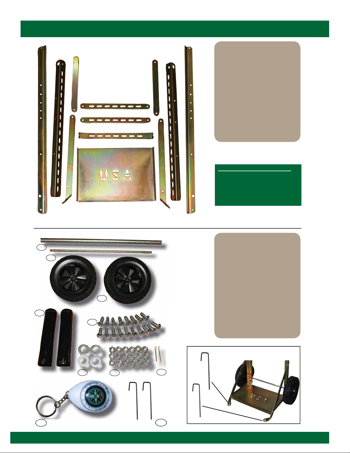
The photo in Fig. 3 shows the holes in the uprights of
the dolly for proper mounting of the angle adjustment
brackets in Step 3. Fig. 3 shows 30°, which is the
optimal angle for Kencove’s Blairsville, PA headquarters.
The included compass allows you to maintain proper
orientation of your solar panel. Panels should
always face true south if you are located in the
northern hemisphere, or true north if in the southern
hemisphere.
Fig. 3
Outtting the Solar Dolly™
The Kencove Solar Dolly™ is designed for
maximum portability, durability and performance
and is an excellent choice for portable and
rotational grazers. Kencove can outfit your solar
dolly with the very best solar panels, energizers
and voltage controllers. For more information
on components and solar powered fencing, call
800-KENCOVE.
The solar dolly at right is outfitted with a 30-
watt panel, 3 J Stafix Dual-Purpose Energizer, 5
amp controller and a deep cycle marine battery
(recommended). All components sold separately.
Page 3

HowtoOutfit the Solar Dolly™
Step 2: Attach the controller
Figure 1a and 1b: To install panel, flip the dolly upside
down as shown. Orient the panel lengthwise across the
panel mounting brackets. Center the panel and make sure
to leave roughly four inches between the panel and the
handlebars for adequate handling of the dolly. Attach panel
via the underside of the panel using a power drill and the
four self-tapping screws included with the dolly.
To attach the solar controller, run the supplied black
zip ties through the holes in the top of the controller
and then through the slots on the controller mounting
bracket. Secure the zip ties.
4”
Step 1: Attach the solar panel
Fig. 1
a.
b.
Deep Cycle Marine Battery
Solar Panel
Solar Controller
12 v Energizer
Battery Cable
le
M
ar
in
e
Ba
tt
er
y
Battery Box
Panel Brackets
Controller
mounting bracket
Energizer
mounting brackets
Prior to initial assembly, be sure battery is fully charged.

Step 3: Attach the energizer
Figures 2a and 2b: Attach energizer to mounting
brackets with supplied white zip ties.
Figures 4a, 4b and 4c: Connect the controller to the battery
with the battery cable. Use a small straight screwdriver to loosen
the middle pair of screws on the front of the controller so the
bare ends of the battery cable can be inserted into the bottom of
the controller (Be sure the battery is already charged). Be sure
the positive/negative wires correspond with the correct slots
on the controller. After securing the wires, attach the jumper
ends of the cable to the battery terminals. The “Bat” light and
the red light in the corner of the controller will show when the
connection is made.
Figures 5a and 5b: Connect the solar panel cable to the controller.
Install the bare wires in the corresponding slots on the left side
of the controller. Once the cable is installed, the “Sun” light will
show.
Figures 6a and 6b: Connect the wires from the energizer to the
controller by inserting them in the slots on the right side of the
controller. After connecting the wires, turn the energizer on to
ensure correct connections. Your Solar Dolly™ electric fencing
system is now ready to be connected to the fence.
Fig. 2
a. b.
Fig. 6
Step 4: Connect the components
Fig. 3
b.
a.
Fig. 4
a.
b.
c.
Fig. 5
b.
a.
a. b.
Figures 3a and 3b: If using a Stafix Dual
Purpose Energizer, remove of alligator clips (mark
positive and negative wires prior to removal). Strip
insulation from wire ends.
Remove