manuals.online logo
Brands
  1. Home
  2. •
  3. Brands
  4. •
  5. Kenmore
  6. •
  7. Air Conditioner
  8. •
  9. Kenmore 25371124012 User manual

Kenmore 25371124012 User manual

READ BEFORE INSTALLING UNiT
For SLO3 Air Conditoner (8K~12K BTU)
To avoid risk of personal injury, property damage, or product damage due to the weight of this device and sharp
edges that may be exposed:
Air conditioners covered in this manual pose an excessive weight hazard. Two or more people are needed to
move and install the unit. To prevent injury or strain, use proper lifting and carrying techniques when moving unit.
Carefully inspect location where air conditioner will be installed. Be sure it will support the weight of the unit over
an extended period of time.
Handle air conditioner with care. Wear protective gloves whenever lifting or carrying the unit. AVOID the sharp
metal fins of front and rear coils.
Make sure air conditioner does not fall during installation.
Tools and Parts:
Gather the required tools and parts before starting installation. Read and follow the instructions provided with any tools
listed here.
TOOLS NEEDED
• Flat-blade and Phillips screwdrivers
• Level
• Tape measure
o Drill and 3/16", 1/8"_ 3/32", or smaller drill bit
Through-the-wall Installation:
In addition to the tools listed above, the following tools are needed for through-the-wall installation.
TOOLS NEEDED
• saw
• 1" (2.5 cm) or thicker lumber
• caulk • #10 X 1" wood screws (7)
Parts Supplied
Check that all parts are included in parts package:
Hardware Qty. Hardware
#10 X 1/2" pan - head
Phillips screws
#10 X 1/2" round - headscrews
#10 X 1/4" pan - head
Phillips screws
Top channel
side curtains
5
2
Window sash seal
Foam seal
window lock bracket
Safety Lock
(for Vinyl-Clad window)
weather seals
(6"X3/4"X1/12")
Qty.
1
2
5
2020217A2086
• Installation parts are supplied for double-hung windows up to 36" (91.4 cm) wide. A special Wide Window Kit is
available from your dealer or service center. See "Accessories."
• Do not use any screws other than those specified here.
Location Requirements:
IMPORTANT:Observe all governing codes and ordinances. Check the location where air conditioner will be installed,
Proper installation is your responsibility, Make sure you have everything necessary for correct installation,
Grounded electrical outlet within 4 ft (122 cm) of where the power cord exits the air conditioner.
Free movement of air in room to be cooled.
A large enough opening for the air conditioner.
Adequate wall support for weight of air conditioner. Air conditioner weights between 70 and 85 Ibs (32 to 40 kgs).
• Do not use an extension cord.
• Cabinet louvers must not be obstructed. Air must be able to pass freely through the cabinet Iouvers.(FIG.1 )
Window Installation:
Window opening measurements (FIG.2) :
26-7/8" to 36" (68.3 cm to 91.4 cm) opening width.
16-1/2" (41.9 cm) minimum opening height.
FIG.1 FIG.2
A
A. Cabinet louvers
r- J
[ !
A. 26-7/8" (68.3 cm) minimum
B. 16-1/2" (41.9 cm) minimum
Remove packaging material:
Remove and dispose of/recycle packaging materials. Remove tape and glue residue from surfaces before installing
the air conditioner. Rub a small amount of liquid dish soap over the adhesive with your fingers. Wipe with warm water
and dry.
Do not use sharp instruments, rubbing alcohol, flammable fluids, or abrasive cleaners to remove tape or glue. These
products can damage the surface of your air conditioner.
Handle the air conditioner gently.
1. Remove the air conditioner from the carton and place it on cardboard.
2. Remove 1 shipping screw from each side of the cabinet (FIG.3).
3. Remove front panel by removing 1 Phillips screw from each side of the front panel. Set screws aside and save
(FIG.4).
4. Pull on the handles to slide the air conditioner out of the cabinet. Place the air conditioner on cardboard (FIG.5).
FIG.3 FIG.4 FIG.5
B
A B
A.shippingscrew B.frontpanelscrew C.handle
C
• Handletheairconditionergently.
• Besureyourairconditionercabinetdoesnotfalloutoftheopeningduringinstallationorremoval.
• Theplacewherethepowercordexitstheairconditonershouldbenomorethan4ft(122cm)fromagrounded
3prongoutlet.
• Donotblockthelouversonthefrontpanel.
o Donotblockthelouversontheoutsideofairconditioner.
® Donotlift,pullorremoveanyexpandedpolystyrene(foam)frominsideoftheairconditioner.Itisnotpacking
material
Attach Top Channel (FIG.6): B FIG.6
• Attach the top channel and side curtains to the air conditioner cabinet before
placing the cabinet in the window.
1. Locate provided bag of screws.
2. Place the top channel on top of the air conditioner cabinet, lining up the three
holes in the top channel with the three holes on top of the air conditioner cabinet.
3. Using three #10 X 1/4" pan-head Phillips thread cutting screws, attach the top
channel to the air conditioner cabinet.
Attach Side Curtains :
1. Locate provided bag of screws.
A. #10 X 1/4" pan-head Phillips
thread cutting screws
B. Top channel
2. Insert the right-hand curtain connector tab into the curtain housing channels on the air conditioner (FIG.7A).
3. Insert the top and then the bottom of the right-hand curtain housing in the top and bottom curtain channels on the
air conditioner (FIG.7B, FIG.7C).
4. Slide the curtain housing into the curtain guides as far as it could go.
5. Repeat the above steps for the left-hand curtain.
FIG.7A A FIG.7B Top view
A B FIG.7C Bottom view
B_
A. Side Curtain A. Curtain housing
B. Curtain top channel
on air conditioner
A. Curtain housing
B. Curtain bottom channel
on air conditioner
Attach foam adhesive seal:
Attach foam adhesive seal along the bottom of the curtain bottom channel (FIG.8).
A. Curtain housing
B. Foam adhesive seal
FIG.9 _g_ket fsCeacbuineetyseated
on edge of inner silt.
_binet
_'neUr°_,, wintdow [--J Bracket
outer sill
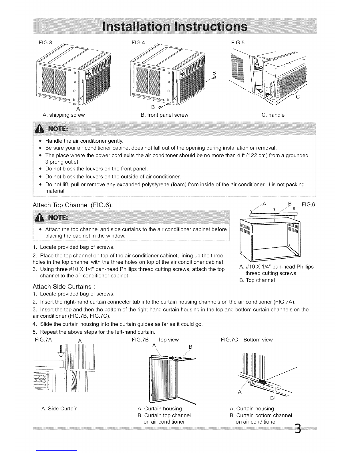
Install Cabinet into Window:
1. Center empty cabinet in window:
FIG.10
I
IA. Window sash
II......................................A
...................B
......................C
I
B. Empty cabinet
C. Window channel
Check that lower rail of air conditioner cabinet is behind and against back side of window sill. Maintain a firm hold on
the air conditioner cabinet (FIG.9). Lower window sash to hold the cabinet in place. Measure the distance between the
right side of the cabinet and the inside of the window channel (FIG.10). Repeat for the left side. Adjust the cabinet until
the distance on each side is the same.
2. Attach the cabinet to window:
A: For wooden window:
Use a 3/16" drill bit to drill three starter holes 3/8" deep through the three holes in the cabinet and into the window sill,
and drill one starter hole 318"deep through the hole in the middle of top rail and into the window frame (FIG.11). Attach
cabinet to window with three #10 x 1/2" pan-head Phillips screws and one #10 X 1/2" round-head screw (FIG.11).
B: For Vinyl-Clad window:
Use a 1/8" drill bit to drill one hole through the hole in the middle of top rail and into the window frame. Attach cabinet
to window with one #10 x 1/2" round-head Phillips screw (FIG.11). Place two safety locks into the holes that located
in the bottom of the cabinet and drive two locking screws through the safety locks into the cabinet as shown (FIG.12)
3. Check that air conditioner cabinet is tilted back 5/16" to 3/8" so that water could run to the outside (See FIG.13).
FIG.11 ..... FIG.12
A A A
A. #10 X 1/2" pan-head Phillips screws A.
B. #10 X 1/2" round-head screw B.
C. Window channel Only for Vinly-Clad Window
FIG.13
w Sash
', ide Louvers
#10 X 1/4" pan-head Phillips screws
Safety Lock Window Sill
Attach Side Curtains to Window Frame:
1. Extend the side curtains out against the window frame
(FIG.11).
2. Drill holes and drive locking screws:
A: For wooden windows:
Use a 3/32" drill bit to drill 4 starter holes through the holes in
the side curtains into the window. Drive four #10 X 1/2" locking
screws through the holes in the side curtains into the window
sill and window frame(FIG.14A, FIG.14B).
B: For Vinyl-Clad windows:
Use a 118"drill bit to drill two holes through the holes in the
side curtains into the window frame as shown (FIG.14A).
Drive two #10 X 112"locking screws through the holes in the
FIG.14B
FIG.14A
B _
A. Window channel A. #10 X 1/2" round-head
B. left-hand curtain
C. #10 X 112"round-head screw
B. Slotted hole in the
side curtains into the window sash (FIG. 14A) screw bottom of the curtain
3. Trim the weather seal (6"X314"X1112") with a proper length, peel off the protective backing and plug any gaps if
needed as shown (FIG.14B).
Complete Installation:
1. Insert window sash seal behind the top of the lower window sash and against
the glass of the upper window (FIG.15).
2. Place the window-lock bracket on top of lower window and against upper
window sash on right side of the window (FIG. 15).
3. Use a 3/32" drill bit to drill starter holes through the holes in the bracket into
the window sash (FIG.15).
4. Attach the window lock-bracket to the window sash with two #10 X 1/2"
round-head screws to secure window in place (FIG.15).
5. Insert air conditioner into cabinet (FIG.16).
6. Insert front tabs of front panel into top of cabinet and swing front into place,
7. Attach bottom front of panel with front panel screws (FIG.17).
8. Plug into a grounded 3 prong outlet.
9. Press RESET on the power supply cord.
FIG.16 FIG.17
FIG.15
D
A. Window lock bracket
B. Upper window glass
C. Window sash seal
D. #10Xl/2" round-head screws
I
Through-the-Wall Cabinet Installation:
Option 1--wood, metal or plastic molding:
When using a wood, metal or plastic molding, the wood frame should line up with the inside wall as shown FIG.18.
Option 2--Plastered wall with no molding:
If the plastered wall is to be flush with the cabinet and no molding is used, the wood frame must be set 1/2" (13mm).
into the inside wall FIG.19.
FIG.18 ABC AB C FIG.19
_i ii iiiii
A. Molding C. Wood frame A. Plastered wall C. Wood frame
B. Inside wall D. Louvers B. Inside wall D. Louvers
Install Wood Frame:
FIG.20
1' _ c
t
A. 16" (40.6 cm) C
B. 22-5/8" (57.5 cm)
C. Wood thickness
D. 2-1/2" (6.4 cm) minimum to
6-1/2"(16.5 cm) maximum
1. Construct the wood frame. See FIG.20 for dimensions.
2. Measure the outside width and height of frame to determine wall opening dimensions, The wall opening
measurements should be :
Width : 22-5/8" (57.5 cm) plus twice thickness of wood used to build frame,
Height: 16" (40.6 cm) plus twice thickness of wood used to build frame,
Depth : 2-1/2" (6.4 cm) minimum to 6-1/2" (16.5 cm) maximum.
3. Cut the opening through the wall. Remove and save insulation.
4. Apply the wood preservative to the outside exposed surface.
5. Insert the frame in the wall opening. Square and level frame.
6. Attach frame securely to the wall.
• Dimensionfordepthdependsonwallthicknessandtypeofmolding
(FIG.21).
o Donotblocklouversinairconditionercabinet.
• Use1"(2.5cm)orthickerlumberforwoodframe. FIG.
A.Outsidewidth C.Depth
B.Outsideheight
Install Cabinet into Wood Frame:
1. Insert cabinet into the framed wall opening. The top of the cabinet should extend 3/4" (19.1 mm) into the room. If
there is trim, the cabinet should extend 3/4" (19.1 mm) past trim (FIG.22).
2. Use a level to check that cabinet is level side to side (FIG.23).
3. Check that air conditioner cabinet is tilted to the outside so that water could run to the outside. The cabinet should
slop at least half-a-bubble towards the rear.
4. Reuse the insulation to seal opening between cabinet and frame.
5. Use existing holes in sides and top of cabinet and seven #10 X 1" wood screws (not provided) to attach cabinet to
frame.
6. Caulk all outside wall openings around cabinet.
• Do not overtighten screws or the cabinet will distort and provide a poor air seal between cabinet and air
conditioner.
...............................a FIG.22
A. 3/4" (19.1 mm) extending into room
B. Trim A. level
Complete Installation:
1. Insert air conditioner into cabinet (FIG.24).
2. Insert front tabs of front panel into top of cabinet and swing front into place.
3. Attach bottom front of panel with front panel screws (FIG.25).
4. Plug into a grounded 3 prong outlet.
5. Press RESET on the power supply cord.
• Handle the air conditioner gently.
• For through-the-wall installations, if needed, install molding around the room side of cabinet.
FIG.24 FIG.25

This manual suits for next models

2

Other Kenmore Air Conditioner manuals

Kenmore 580.71184 User manual

Kenmore

Kenmore 580.71184 User manual

Kenmore 580.76081 User manual

Kenmore

Kenmore 580.76081 User manual

Kenmore 580.73083 User manual

Kenmore

Kenmore 580.73083 User manual

Kenmore Kenmore 580.76129 User manual

Kenmore

Kenmore Kenmore 580.76129 User manual

Kenmore 309000845 User manual

Kenmore

Kenmore 309000845 User manual

Kenmore 580.71122 User manual

Kenmore

Kenmore 580.71122 User manual

Kenmore Air Conditioner User manual

Kenmore

Kenmore Air Conditioner User manual

Kenmore 580.74121 User manual

Kenmore

Kenmore 580.74121 User manual

Kenmore 580.75100 User manual

Kenmore

Kenmore 580.75100 User manual

Kenmore 580.72066 User manual

Kenmore

Kenmore 580.72066 User manual

Kenmore 78073 User manual

Kenmore

Kenmore 78073 User manual

Kenmore 580.74066 User manual

Kenmore

Kenmore 580.74066 User manual

Kenmore 580.76100 User manual

Kenmore

Kenmore 580.76100 User manual

Kenmore 25370062011 User manual

Kenmore

Kenmore 25370062011 User manual

Kenmore 25376150410 User manual

Kenmore

Kenmore 25376150410 User manual

Kenmore 580.74125 User manual

Kenmore

Kenmore 580.74125 User manual

Kenmore 253.71123 User manual

Kenmore

Kenmore 253.71123 User manual

Kenmore Kenmore 580.73093 User manual

Kenmore

Kenmore Kenmore 580.73093 User manual

Kenmore 35915 User manual

Kenmore

Kenmore 35915 User manual

Kenmore 580.75050 User manual

Kenmore

Kenmore 580.75050 User manual

Kenmore 253.76125 User manual

Kenmore

Kenmore 253.76125 User manual

Kenmore 78122 User manual

Kenmore

Kenmore 78122 User manual

Kenmore 580.75281 User manual

Kenmore

Kenmore 580.75281 User manual

Kenmore 35090 User manual

Kenmore

Kenmore 35090 User manual

Popular Air Conditioner manuals by other brands

Carrier Fan Coil 42B Installation, operation and maintenance manual

Carrier

Carrier Fan Coil 42B Installation, operation and maintenance manual

CLIMAVENETA a-CHD U-2T 606+2209 OPERATING AND INSTALLATION Manual

CLIMAVENETA

CLIMAVENETA a-CHD U-2T 606+2209 OPERATING AND INSTALLATION Manual

Frigidaire FRS09PYW1 installation guide

Frigidaire

Frigidaire FRS09PYW1 installation guide

Mitsubishi Electric MSZ-LN18VG2W operating instructions

Mitsubishi Electric

Mitsubishi Electric MSZ-LN18VG2W operating instructions

Maplin A75TB user manual

Maplin

Maplin A75TB user manual

Fujitsu General ASHH30KMTB Service manual

Fujitsu

Fujitsu General ASHH30KMTB Service manual

Mitsubishi Electric Mr.SLIM MS24WN Service manual

Mitsubishi Electric

Mitsubishi Electric Mr.SLIM MS24WN Service manual

Panasonic CU-QE12MKE Service manual

Panasonic

Panasonic CU-QE12MKE Service manual

Daikin FFQ25B9V1B Operation manual

Daikin

Daikin FFQ25B9V1B Operation manual

GE AHE18 Series Owner's manual and installation instructions

GE

GE AHE18 Series Owner's manual and installation instructions

Trane TTK060K4 Product bulletin

Trane

Trane TTK060K4 Product bulletin

Mitsubishi Electric MSC-GE20VB operating instructions

Mitsubishi Electric

Mitsubishi Electric MSC-GE20VB operating instructions

LG LMU365HV Specifications

LG

LG LMU365HV Specifications

Beko BEP 09C user manual

Beko

Beko BEP 09C user manual

Whirlpool BHAC1000XS0 Use & care guide

Whirlpool

Whirlpool BHAC1000XS0 Use & care guide

Lennox FLEXY FX 025 Application guide

Lennox

Lennox FLEXY FX 025 Application guide

Samsung AS07P2GE/XCH Owner's instructions

Samsung

Samsung AS07P2GE/XCH Owner's instructions

Sanyo THX2452 user manual

Sanyo

Sanyo THX2452 user manual

manuals.online logo
manuals.online logoBrands
  • About & Mission
  • Contact us
  • Privacy Policy
  • Terms and Conditions

Copyright 2025 Manuals.Online. All Rights Reserved.