Kenmore 233.5996 Series User manual

Use & Care / Installation Manual
Manual de Uso y Cuidado / Instalación
English / Español
Models/Modelos 233.5996*
Kenmore Elite®
Downdraft Blower
Ventilador de tiro descendente
* = color number, número de color
P/N 99044658A
Sears Brands Management Corporation,
Homan Estates, IL 60179 USA
www.kenmore.com
www.sears.com
TM

2
TABLE OF CONTENTS
SECTION ....................................................................... PAGE
Warranty ............................................................................................ 2
Safety Instructions ............................................................................ 3
Operation ........................................................................................... 3
Cleaning, Servicing ..........................................................................4
Parts Included With Downdraft ..................................................... 4
Tools Needed For Installation ........................................................ 4
Equivalent Duct Length Chart ........................................................ 5
Prepare The Downdraft Location .................................................. 6
Prepare The Downdraft ...................................................................7
Install The Downdraft ....................................................................... 8
Connect The Wiring ......................................................................... 9
Complete The Installation ..............................................................10
Master Protection Agreements .....................................................10
Service Parts ......................................................................................11
READ AND SAVE THESE INSTRUCTIONS
When this appliance is installed, operated and maintained according to all
supplied instructions, the following warranty coverage applies. To arrange for
warranty service, call 1-800-4-MY-HOME® (1-800-469-4663).
• For one year from the date of purchase, any part of this product that fails
due to a defect in material or workmanship will receive free repair or replace-
ment if repair proves impossible. The length of this coverage does not apply
to the nish of any painted or bright metal part.
• For thirty days date of purchase, any painted or bright metal part of this
product will be replaced free of charge if its nish is defective in material or
workmanship.
All warranty coverage is void if this product is ever used for other than private
household purposes.
This warranty covers only defects in material and workmanship, and will
NOT pay for:
1. Consumable parts that can wear out from normal use, including but not
limited to lters, belts, light bulbs, and bags.
2. A service technician to instruct the user in correct product installation,
operation or maintenance.
3. A service technician to clean or maintain this product.
4. Damage to or failure of this product if it is not installed, operated or
maintained according to the all instructions supplied with the product.
5. Damage to or failure of this product resulting from accident, abuse, misuse
or use for other than its intended purpose.
6. Damage to or failure of this product caused by the use of detergents,
cleaners, chemicals or utensils other than those recommended in all instruc-
tions supplied with the product.
7. Damage to or failure of parts or systems resulting from unauthorized
modications made to this product.
Disclaimer of implied warranties; limitation of remedies
Customer’s sole and exclusive remedy under this limited warranty shall be
product repair as provided herein. Implied warranties, including warranties
of merchantability or tness for a particular purpose, are limited to one year
or the shortest period allowed by law. Sears shall not be liable for incidental
or consequential damages. Some states and provinces do not allow the
exclusion or limitation of incidental or consequential damages, or limitation
on the duration of implied warranties of merchantability or tness, so these
exclusions or limitations may not apply to you.
This warranty gives you specic legal rights, and you may also have other
rights which vary from state to state.
Sears Brands Management Corporation, Homan Estates, IL 60179
KENMORE LIMITED WARRANTY

3
OPERATION
Warranty Safety CleaningOperation Installation Service Parts
Always turn the downdraft blower on before you begin cooking
to establish an air ow in the kitchen. Let the blower run for a few
minutes to clean the air after you turn the cooktop o. This will
keep the whole kitchen cleaner and brighter.
CONTROLS
NOTE
For most convenient operation, set the blower to your favorite
speed. The blower will come on to this speed whenever the
activating switch is pressed and the air vent rises.
HEAT SENTRY
When chimney is UP and blower is ON (at any speed) or OFF:
If the exhaust temperature becomes higher than expected, the Heat
Sentry mode will activate and increase the blower speed to HIGH.
Lowering the chimney will turn blower OFF - even if Heat Sentry
is active.
WARNING
TO REDUCE THE RISK OF FIRE, ELECTRIC SHOCK, OR INJURY TO PER-
SONS, OBSERVE THE FOLLOWING:
1. Use this unit only in the manner intended by the manufacturer. If you
have questions, contact the manufacturer at the address listed in the
warranty.
2. Before servicing or cleaning unit, switch power o at service panel
and lock the service disconnecting means to prevent power from being
switched on accidentally. When the service disconnecting means cannot
be locked, securely fasten a prominent warning device, such as a tag,
to the service panel.
3. Installation work and electrical wiring must be done by a qualied
person(s) in accordance with all applicable codes and standards,
including re-rated codes and standards.
4. Sucient air is needed for proper combustion and exhausting of
gases through the ue (chimney) of fuel burning equipment to prevent
backdrafting. Follow the heating equipment manufacturer’s guideline and
safety standards such as those published by the National Fire Protection
Association (NFPA), and the American Society for Heating, Refrigeration
and Air Conditioning Engineers (ASHRAE), and the local code authorities.
5. When cutting or drilling into wall or ceiling, do not damage electrical
wiring and other hidden utilities.
6. Do not use this unit with an additional speed control device.
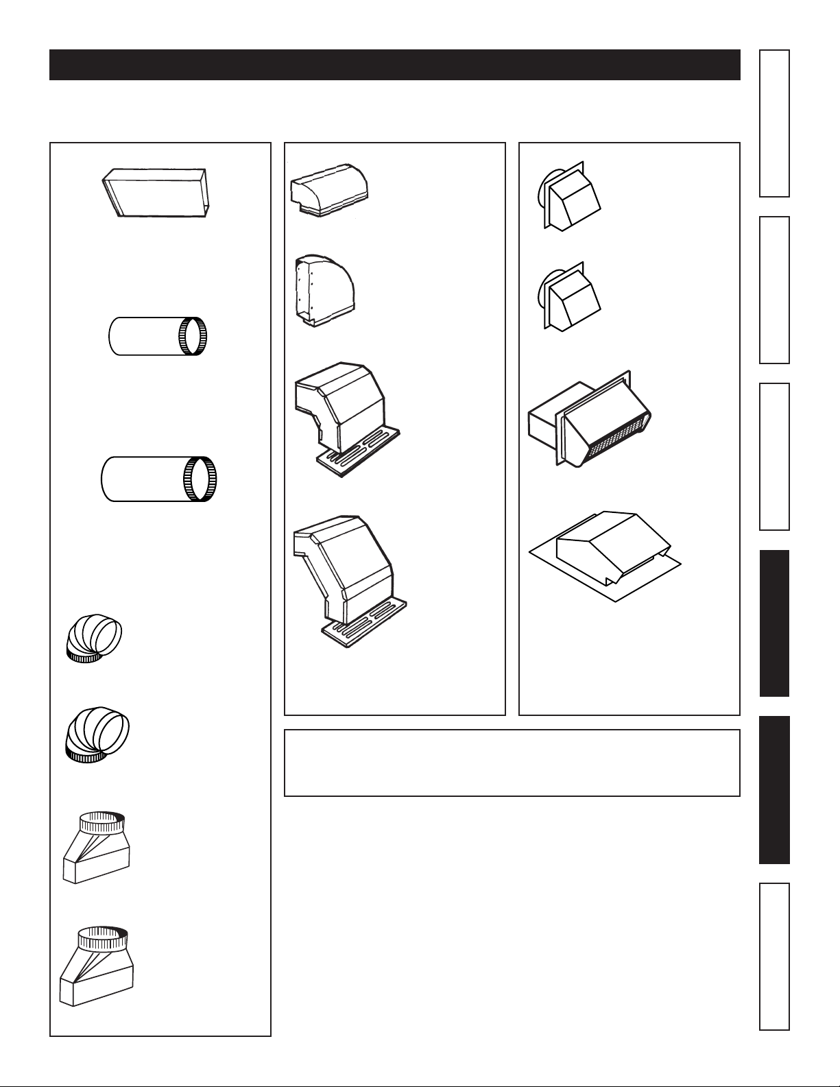
7. Ducted fans must always be vented to the outdoors.
8. To reduce the risk of re, use only metal ductwork.
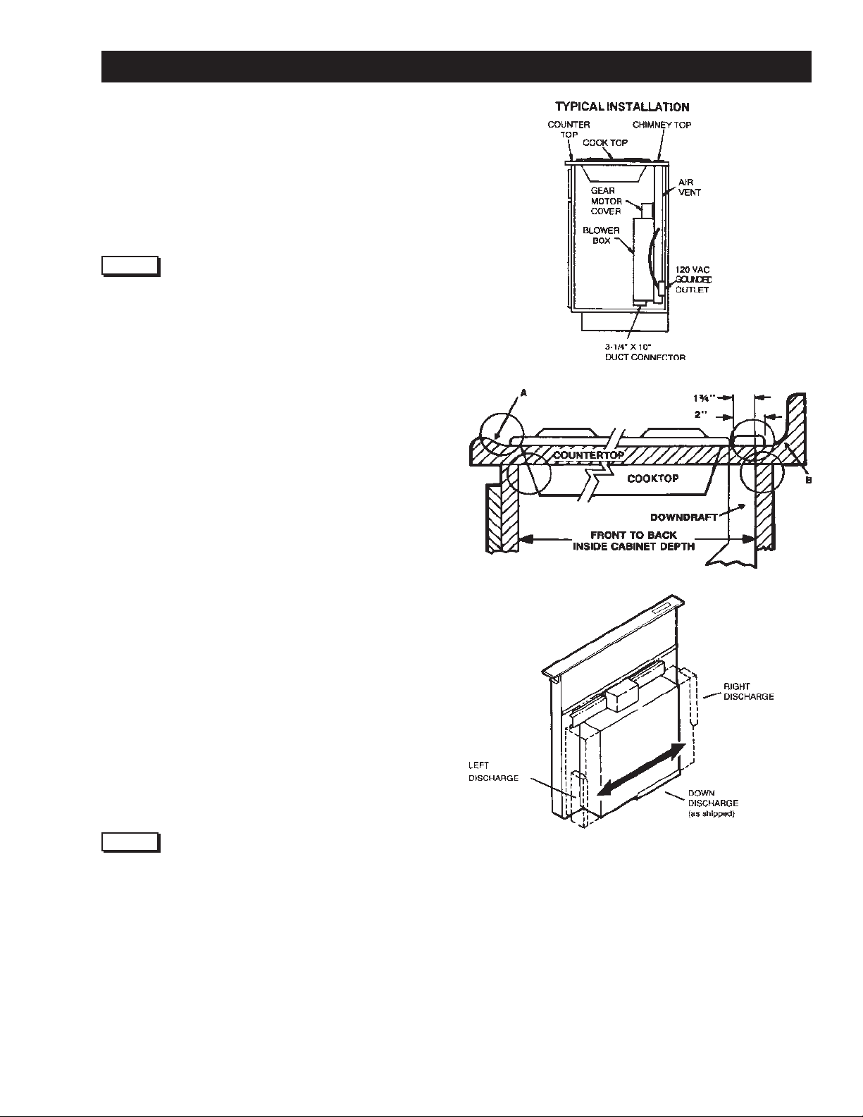
9. Do not install this product with the activating switch directly behind a
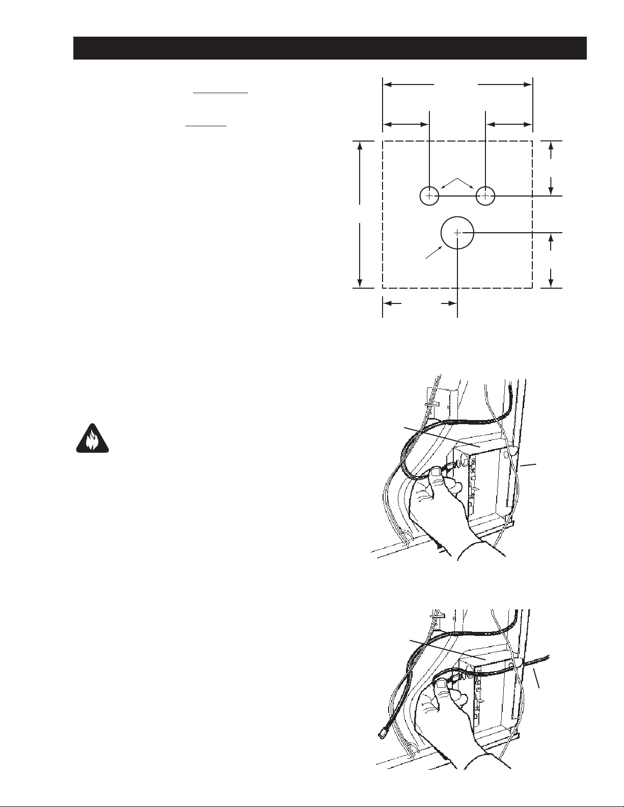
burner or element. Minimum distance between the switch and the edge
of the burner should be 4 inches.
10. Loose-tting or hanging clothing should never be worn when operating
this appliance. They may be ignited by burners/elements on cooktop.
11. Children should not be left alone or unattended in the area where this
appliance is in use.
12. This unit must be grounded.
TO REDUCE THE RISK OF A RANGE TOP GREASE FIRE:
1. Never leave surface units unattended at high settings. Boilovers cause
smoking and greasy spillovers that may ignite. Heat oils slowly on low
or medium settings.
2. Always turn hood ON when cooking at high heat or when cooking
aming foods.
3. Clean ventilating fans frequently. Grease should not be allowed to
accumulate on fan or lter.
4. Use proper pan size. Always use cookware appropriate for the size of
the surface element.
TO REDUCE THE RISK OF INJURY TO PERSONS IN THE EVENT OF A
RANGE TOP GREASE FIRE, OBSERVE THE FOLLOWING:*
1. SMOTHER FLAMES with a close-tting lid, cookie sheet, or metal
tray, then turn o the burner. BE CAREFUL TO PREVENT BURNS. If the
ames do not go out immediately, EVACUATE AND CALL THE FIRE
DEPARTMENT.
2. NEVER PICK UP A FLAMING PAN - You may be burned.
3. DO NOT USE WATER, including wet dishcloths or towels - a violent steam
explosion will result.
4. Use an extinguisher ONLY if:
A. You know you have a Class ABC extinguisher and you already know
how to operate it.
B. The re is small and contained in the area where it started.
C. The re department is being called.
D. You can ght the re with your back to an exit.
* Based on “Kitchen Firesafety Tips” published by NFPA.
CAUTION
1. For general ventilating use only. Do not use to exhaust hazardous or
explosive materials and vapors.
2. To avoid motor bearing damage and noisy and/or unbalanced impellers,
keep drywall spray, construction dust, etc. o power unit.
3. Clean lters and grease-laden surfaces frequently.
4. Do not repair or replace any part of this appliance unless specically
recommended in this manual. All other servicing should be done by a
qualied technician.
5. Please read specication label on product for further information and
requirements.
SAFETY INSTRUCTIONS
INTENDED FOR DOMESTIC COOKING ONLY
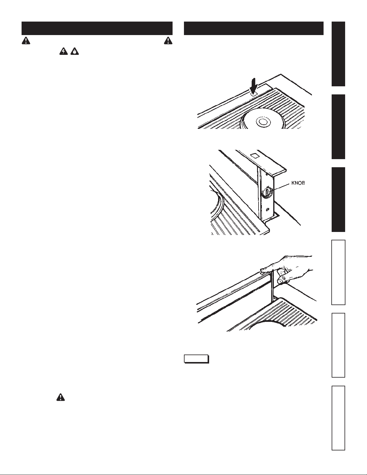
Turn the downdraft blower ON by pressing down on the activating
switch. The air vent will rise.
The blower can be turned ON or OFF and its speed can be adjusted
with the recessed knob on the right side of the air vent.
Turn the downdraft blower OFF by pressing the activating switch
again. The air vent will go down and the blower will shut OFF.

4
PARTS INCLUDED WITH DOWNDRAFT
TOOLS NEEDED FOR INSTALLATION
Screwdriver
(Flat & Phillips) Pencil
Tape
Measure
Drill
Sabre
Saw
Keyhole
Saw
-or-
1/4"
Nutdriver
Duct Tape Wire
Stripper
Aluminum Grease Filters
(Qty. 2)
Parts Bag
(Contains leveling brackets
& mounting hardware.)
WARNING: Always disconnect electric power supply
before cleaning unit.
Use a mild detergent suitable for painted surfaces. DO NOT USE
ABRASIVE CLOTH, STEEL WOOL PADS, OR SCOURING POWDERS.
Vacuum blower to clean. Do not immerse blower in water.
Wash the 2 aluminum grease lters in a mild detergent solution or
a dishwasher. Remove them from the air vent by grasping the tab at
the top of each lter.
CLEANING
NOTE
The lters are dierent sizes. Be sure to replace them as removed
(wider one on the left), with tabs UP.
It may be necessary to remove the downdraft blower system from
the cabinet in order to service components such as the blower motor
or air vent mechanism.
Disconnect power to the cooktop and remove it rst. Reverse the steps
under “MOUNT THE UNIT” to remove the downdraft from the cabinet.
WARNING: Always disconnect electric power supply
before servicing unit.
SERVICING

5
EQUIVALENT DUCT LENGTH CHART
Broan Model 401
Straight Duct
3¼-in. x 10-in. x 2-ft. long
Equivalent length
2 ft.
Broan Model 406
Straight Duct
6-in. round x 2-ft. long
Equivalent length
2 ft.
Broan Model 415
7-in. Round Elbow
Equivalent length
8 ft.
Sears Model 59581
3¼-in. x 10-in. to
6-in. Round Transition
Equivalent length
5.5 ft.
Broan Model 428
3¼-in. x 10-in.
Right-angle Elbow
Equivalent length
8.5 ft.
Broan Model 429
3¼-in. x 10-in.
Right-angle Flat Elbow
Equivalent length
24 ft.
Broan Model 430
3¼-in. x 10-in.
Right-angle
Short
Eave Elbow
Equivalent length
15 ft.
Broan Model 431
3¼-in. x 10-in.
Right-angle
Long
Eave Elbow
Equivalent length
15 ft.
Sears Model 59691
6-in. Round
Wall Cap
Equivalent length
34 ft.
(6-ft. w/o damper)
Sears Model
59391
3¼-in. x
10-in.
Wall Cap
Equivalent
length
45 ft.
(7-ft. w/o damper)
Sears
Model 59091
Roof Cap
(accepts 7-in. round
or 3¼-in. x 10-in. duct)
Equivalent length
30 ft. (7-ft. w/o damper)
Warranty Safety CleaningOperation Installation Service Parts
Kenmore downdrafts are designed to perform eciently when attached to long runs of duct. As a point of reference, this hood will func-
tion at approximately 80% of its rated air ow when 200 equivalent feet of 7" round ductwork is attached. Use this chart to calculate the
equivalent duct length of your system.
Broan Model 407
Straight Duct
7-in. round x 2-ft. long
Equivalent length
2 ft.
Broan Model 419
6-in. Round Elbow
Equivalent length
8 ft.
Broan Model 412H
3¼-in. x 10-in. to
7-in. Round
Transition
Equivalent length
5.5 ft.
Broan Model 647
7-in. Round
Wall Cap
Equivalent length
34 ft.
(6-ft. w/o damper)
Sears Model “Ducting Accessories” available by calling Sears at
1-800-4-MY-HOME®
Broan Model “Ducting Accessories” available by calling:
1-800-558-1711.

6
PREPARE THE DOWNDRAFT LOCATION
PLANNING
This downdraft blower system is designed to be used to exhaust
airborne contaminants when cooking with a variety of gas or electric
cooktops. It can be mounted in island, peninsula, or conventional
wall locations.
This unit can be easily installed following these basic steps:
Cut out the countertop opening.
Mount the unit in the cabinet.
Connect the ductwork and electrical.
Install the cooktop.
NOTE
The high level of air ow of this appliance may aect the gas ame
on some types of gas cooktops. This is NORMAL and will cause no
harm, but can be corrected by lowering the speed of the blower.
TAKE MEASUREMENTS
1. Refer to the cooktop installation instructions for dimensions of
cooktop, countertop cut-out, and cabinet requirements. The Model
59960 will t in most 30" wide cabinets and the Model 59966
will t in most 36" wide cabinets. However, it is recommended
that oversized cabinets be used for easier installation.
2. Cooktop depth can vary greatly from one to another. This may
cause the t of these two appliances to be rather tight.
Pay special attention to the areas of potential interference highlighted
above. A countertop with (A) a raised lip and/or (B) a backsplash
may not allow enough at countertop for a proper installation. Note
that 2" of at countertop is required behind cooktop and that 1-3/4"
is necessary between the back edge of the cooktop and the inside
of cabinet back.
PLAN THE DUCTWORK
1. This downdraft blower system is designed for use with
3-1/4" x 10" ductwork (can be transitioned to 6" round). Three
dierent discharge directions are available with side-to-side
adjustment for accurate alignment of ductwork.
2. For best performance: Choose the ducting option which allows
the shortest length of ductwork and a minimum number of elbows
and transitions. Check location of oor joists, wall studs, electrical
wiring or plumbing for possible interference. NOTE: The unit is
shipped with the 3-1/4" x 10" discharge facing DOWN. See
“CHANGING BLOWER DISCHARGE” on page 7, if necessary.
3. The system will operate most eciently when the ductwork does
not exceed 40 feet of equivalent duct. The chart, above, shows
equivalent feet of elbows and transitions. The number of feet of
straight duct plus the equivalent feet of transitions and/or elbows
to be used should equal 40 feet or less.
NOTE
The equivalent feet of various roof and wall caps has been taken into
consideration. Do not include them in this calculation.
PLAN THE WIRING
1. The downdraft blower system draws 4 AMPS and requires a 120
VAC, 60 Hz circuit.
2. The unit has a 2 ft. long power cord with a 3-pronged plug. Plan to
provide a grounded outlet in a location which will allow the unit’s
power cord to reach. (Note: If the Model 59940 is being installed
in a 30" wide cabinet or the Model 59946 is being installed in a
36" wide cabinet, the outlet cannot be located on the back wall
of cabinet.) Outlet may also be wall-mounted, with access hole
in cabinet.

7
PREPARE THE DOWNDRAFT
Warranty Safety CleaningOperation Installation Service Parts
CHANGING BLOWER DISCHARGE (Optional)
The blower is shipped with its discharge facing DOWN. Follow these
steps ONLY if:
• the position of the blower discharge needs to be moved so
ductwork does not interfere with oor joists, plumbing or
wiring below.
• it is necessary to rotate the blower discharge to the RIGHT
or LEFT.
Place the unit on its back on a table or work surface.
DOWN DISCHARGE - MOVING BLOWER LEFT OR RIGHT
1. Loosen the 4 nuts and 2 clamp channels.
2. Slide blower to desired position.
3. Use supplied cover plate to close open space (if any).
4. Tighten nuts to secure top of blower and use sheet metal screws
through bottom ange to secure bottom of blower.
LEFT OR RIGHT DISCHARGE
1. Removethe 4 nuts and 2 clamp channels.
2. Carefully lift blower and disconnect motor plug if necessary.
Reposition blower and RECONNECT MOTOR PLUG.
3. Use supplied cover plate to close open space (if any).
4. Replace clamp channels and use nuts to secure the blower in its
new position.
5. Use sheet metal screws through bottom ange to secure bottom
of blower.

8
INSTALL THE DOWNDRAFT
6" RD.
ELBOW &
DUCTWORK
CUT COUNTERTOP OPENING
1. Lay out and cut the cooktop cut-out far enough FORWARD so
downdraft will t behind it.
2. Set cooktop in place and slide it as far forward as possible. Center
and square it with edges of countertop.
3. Place the plastic template against the back ange of the cooktop
and center it. Trace around template to mark the downdraft
opening.
4. Remove cooktop from countertop.
5. Cut downdraft opening. Be careful not to chip edges of countertop.
MOUNT THE UNIT
1. Set downdraft into opening. Extend leveling brackets to oor of
cabinet so downdraft sits straight. (Note: Leveling brackets can
be removed and re-attached in other positions. Bottom ange
may have to face inward in tight cabinet installations.)
2. Secure the downdraft to the countertop as follows: Hold the
downdraft against the back of countertop cut-out and tightening
the 2 mounting screws (one on each end of unit) on underside of
countertop. Use a wood shim between screw and underside of
granite countertops.
3. Screw leveling brackets to bottom of cabinet. Tighten screws
holding leveling bracket to unit on each side.
INSTALL DUCTWORK
CAUTION: BEFORE CUTTING HOLE IN CABINET FOR
DUCTWORK: Check for interference with oor joists, wall
studs, electrical wiring or plumbing.
NOTE
A 3-1/4" x 10" collar is provided for installers who prefer to rivet
the ductwork to the unit. This will allow blower to be removed and
replaced easily in service situations without disturbing ductwork.
1. Cut hole in cabinet as well as holes in wall or oor as necessary.
2. Mount the roof or wall cap and work back towards the cabinet,
attaching all ductwork, elbows and transitions as previously
planned. Tape all ductwork connections to make them secure
and air tight.
3. Connect ductwork (and transition, if required) to downdraft. If
necessary, LOOSEN nuts and screws that hold the blower in place,
and slide blower left or right to meet ductwork. Re-tighten screws
and nuts.

9
Warranty Safety CleaningOperation Installation Service Parts
CONNECT THE WIRING
WIRING DIAGRAMINSTALL ELECTRICAL WIRING
1. The Downdraft Blower system draws 4 AMPS and requires a 120
VAC, 60 Hz circuit.
2. The unit has a 18 in. long power cord with a 3-pronged plug. Plan
to provide a grounded outlet in a location which will allow the
unit’s power cord to reach.
IMPORTANT - LOCATION OF ELECTRICAL OUTLET:
If Model 59960 is being installed in a 30" wide cabinet...
- or -
If Model 59966 is being installed in a 36" wide cabinet...
...the outlet cannot be located on the back wall of cabinet.
In these cases, the width of the downdraft covers nearly the
entire width of the back wall of the cabinet. So you must
either:
• mount the electrical box to a side wall or cabinet
oor - at least 12 inches from the back wall.
• mount the electrical box to a wall stud behind the
cabinet - where it will not be covered by the downdraft.
Then provide a clearance hole in the back wall of the
cabinet.
3. Mount a standard wiring box, with 3-pronged receptacle, inside
the cabinet. Make sure the downdraft’s power cord can easily
reach it.
4. Run appropriate power cable into cabinet and connect it to
receptacle.
5. Plug the downdraft’s power cord into the outlet.
COMPLETE THE INSTALLATION
WARNING: To avoid possible electrical shock, per-
sonal injury or death - Disconnect electrical power.
INSTALL COOKTOP
1. Align the cooktop with the downdraft and fasten cooktop in place.
NOTE
Accurate alignment of cooktop and downdraft is necessary to ensure
that there is no interference when air vent is raised and lowered.
There should be a gap of 1/32"-1/16" between the back of the cooktop
and the front of the downdraft cover.
ADJUSTMENT
The downdraft is factory-adjusted for proper operation. However,
shipping and handling may aect the position of the activating switch.
To adjust position of activating switch:
1. If downdraft is plugged into electrical outlet, unplug it.
2. Lift air vent straight up and cock it slightly so it remains in the UP
position.
3. Remove switch cover from right end of air vent.
4. Loosen the 2 screws holding the switch bracket in place. Position
switch bracket so that activating switch just comes in contact with
underside of switch membrane. Tighten screws.
5. Replace switch cover, gently lower air vent into chimney, and plug
in power cord. Re-connect electrical power and check operation.
a

10
Installation
1. Using the template at right, lay out the 3-hole pattern on the
counter top. Mark the centers of the three holes to be drilled.
2. Carefully drill the three holes through the counter top. Be careful
not to damage or chip the counter top surface when drilling the
holes.
3. Remove the control from the plastic bag. Line the control up with
the three holes and position the control so it is parallel with the
front of the counter top.
4. Remove the two nylon thumbnuts from the plastic bag and thread
onto the two studs on the control from below the counter top.
Hand tighten only.
WARNING: To reduce the risk of burns or ignition of cloth-
ing by reaching across burners, the remote control must
be mounted at least 4" away from any cook top burner.
CUT OUT ON DOTTED LINE
0.250
DIA. HOLES
0.438
DIA. HOLE
2.000
2.000
.750
.750
1.000
.625 .625
5. Remove the blower, clamp channels, and gearmotor cover from
downdraft (see"Prepare the Downdraft" on page 5). Remove the
large panel to expose the downdraft's wiring.
6. At the lower right hand corner of downdraft, unplug the cable
from the left side of the wiring box.
7. Remove remote cable from the plastic bag and plug into back of
control from below counter top. Route cable through cabinet to
lower right hand corner of downdraft and through the clearance
holes in the side of downdraft and wiring box. Plug cable into
circuit board plug, as shown.
8. Stu excess cable out of the way, secure the cable so it is not
damaged by items stored in the cabinet, and reassemble down-
draft.
When to use the Remote UP/DOWN Control
The Remote UP/DOWN Control should be used when your cooktop
has a burner that is within 4 inches of the UP/DOWN Button on the
downdraft chimney.
The Remote UP/DOWN Control can be used for convenient UP/DOWN
operation of the downdraft chimney (even when a burner is more
than 4 inches from the UP/DOWN Button of the downdraft chimney).
How to use the Remote UP/DOWN Control
Do not place the remote control where it will interfere with cooking,
where hot pans could be set, or where hot liquids could be spilled
on the control.
The Remote UP/DOWN Control disables the UP/DOWN function of
the UP/DOWN Button on the downdraft chimney.
CABINET
FLOOR
LOWER
RIGHT
SIDE
OF
DOWNDRAFT
CUT OUT ON DOTTED LINE
WIRING
BOX
REMOTE
CABLE
WIRING
BOX
REMOTE UP/DOWN CONTROL INSTALLATION (optional)

11
Warranty Safety CleaningOperation Installation Service Parts
MASTER PROTECTION AGREEMENTS
Congratulationsonmakingasmartpurchase.Your new Kenmore®
product is designed and manufactured for years of dependable
operation. But like all products, it may require preventive mainte-
nance or repair from time to time. That’s when having a Master
Protection Agreement can save you money and aggravation.
PurchaseaMasterProtectionAgreementnowandprotectyourself
fromunexpectedhassleandexpense.
The Master Protection Agreement also helps extend the life of your
new product. Here’s what’s included in the Agreement:
Expert service by our 12,000 professional repair specialists
Unlimited service and no charge for parts and labor on all
covered repairs
“No-lemon” guarantee – replacement
of your covered product if four or more product failures occur
within twelve months
Product replacement if your covered product can’t be xed
Annual Preventive Maintenance Check at your request – no
extra charge
Fast help by phone – phone support from a Sears technician
on products requiring in-home repair, plus convenient repair
scheduling
Power surge protection against electrical damage due to
power uctuations
Rental reimbursement if repair of your covered product takes
longer than promised
Once you purchase the Agreement, a simple phone call is all that
it takes for you to schedule service. You can call anytime day or
night, or schedule a service appointment online.
Sears has over 12,000 professional repair specialists, who have
access to over 4.5 million quality parts and accessories. That’s the
kind of professionalism you can count on to help prolong the life
of your new purchase for years to come. Purchase your Master
Protection Agreement today!
Some limitations and exclusions apply.
For prices and additional information call
1-800-827-6655.
Sears Installation Service
ForSearsprofessionalinstallation of home
appliances, garage door openers, water heaters, and other major
home items, in the U.S.A. call 1-800-4-MY-HOME®
SERVICE PARTS
KEY 30N 36N
NO. WIDTH WIDTH DESCRIPTION
1 97018403 97018404 TOPCOVER
2 99140195 99140195 FILTERSPRING
3 99230345 99230345 POPRIVET
4 97015970 97015971 CHIMNEYWELDMENT
5 97015874 97015874 ENDCAPRH
6 98009358 98009358 ENDCAPLR
7 97015973 97015973 MACHINEDCHIMNEYSLIDE
8 98010013 98010013 MACHINEDAIRBOXSLIDE
9 99160421 99160421 SCREWRHM8-32x.375
10 99160419 99160419 SCREW8-32x..500PHL
11 99271218 99271218 GROUNDWIRE
12 99150471 99150471 SCREW10-32x.500TYPCAPH
13 97015841 97015842 FILTER
14 99710032 99710032 SPACER
15 99111184 99111184 SLIDESTRIPS
16 97015974 97015975 AIRBOXWELDMENT
17 99271210 99271210 CORDSET
18 99400060 99400060 STRAINRELIEFBUSHING
19 99271295 99271295 WIREHARNESS
20 99271292 99271292 SWITCHASSEMBLY
21 99271291 99271291 CONTROLBOARD
22 97015674 97015674 CRANKASSEMBLY
23 97017023 97017023 GEARMOTORBRACKET
24 97017014 97017015 GEARMOTORKIT(INCLUDES
KEYNOS.23&27ON36NMODEL)
26 98009802 97017024 FRONTAIRBOXBOTTOM
27 97017012 97017013 GEARMOTORCOVER
28 98008158 98008158 AIRBOXOPENINGCOVER
29 98009773 98009773 AIRBOXCLAMP
30 99260488 99260488 WHIZNUT10-24
31 97017025 97017025 SCROLLBOXASSEMBLY
32 98008150 98008150 SCROLLBOXCOVER
33 98008157 98008157 CAPACITORCLAMP
34 98008167 98008167 EXT-SCROLLBOXWELDMENT
35 99080362 99080362 MOTORW/CAPACITOR
36 99020247 99020247 BLOWERWHEEL
37 99100484 99100484 MOTORMOUNTISOLATOR
38 99260477 99260477 WHIZNUT1/4-20
39 99030323 99030323 THERMOSTAT
46 98010010 98010010 THERMOSTATBRACKET

12
TABLA DE CONTENIDO
SECCIÓN ........................................................................... PÁGINA
Garantía ......................................................................................................12
Instrucciones de seguridad ......................................................................13
Operación ...................................................................................................13
Limpieza y servicio ....................................................................................14
Piezas incluidas con el ventilador de tiro
descendente ................................................................................................14
Herramientas necesarias para la instalación ......................................14
Cuadro de longitudes equivalentes de ducto ......................................15
Prepare la ubicación del ventilador de tiro
descendente ................................................................................................16
Prepare el ventilador de tiro descendente ...........................................17
Instale el ventilador de tiro descendente .............................................18
Haga las conexiones eléctricas ..............................................................19
Termine la instalación ..............................................................................20
Acuerdos de Protección Maestros .........................................................20
Piezas de servicio ......................................................................................21
LEA Y CONSERVE ESTAS INSTRUCCIONES
GARANTÍA LIMITADA DE KENMORE
Si se instala, opera y mantiene este electrodoméstico con-
forme a todas las
instrucciones suministradas, se aplica la siguiente cobertura
de garantía. Para disponer servicio bajo garantía, llame al
1-800-4-MY-HOME® (1-800-469-4663).
• Durante un año desde la fecha de compra, cualquier parte
de este producto que falle debido a un defecto en material o
mano de obra recibirá reparación o sustitución gratuita si se
hace imposible repararlo. La duración de esta cobertura no
es aplicable al acabado de ninguna pieza de metal brillante
o pintada.
• Durante treinta días desde la fecha de compra, se reem-
plazará sin cargo toda parte de metal brillante o pintada
de este producto si está defectuoso su acabado en cuanto a
material o mano de obra.
Toda cobertura de garantía queda nula si se utiliza este pro-
ducto para otro n que no sea su uso en una casa particular.
Esta garantía cubre solamente defectos en material y mano
de obra, y NO abarca:
1. Piezas consumibles que pueden desgastarse por el uso
normal, como ltros, correas, bombillas y bolsas, entre otras.
2. Un técnico de servicio para indicar al usuario la insta-
lación, operación o el mantenimiento correcto del producto.
3. Un técnico de servicio para estar a cargo de la limpieza y
el mantenimiento de este producto.
4. Daños o fallas de este producto si no se instala, opera o
mantiene conforme a todas las instrucciones entregadas con
el producto.
5. Daños o fallas de este producto resultantes de accidente,
maltrato, uso indebido o utilización distinta del propósito del
producto.
6. Daño o avería de este producto causada por el uso de de-
tergentes, limpiadores, agentes químicos o utensilios que no
sean los recomendados en todas las instrucciones entregadas
con el producto.
7. Daño o falla de piezas o sistemas resultante de modica-
ciones no autorizadas realizadas a este producto.
Limitación de garantías implícitas; limitación de remedios
El único y exclusivo remedio del cliente conforme a esta
garantía limitada será la reparación del producto como se
indica aquí. Las garantías implícitas, como garantías de co-
merciabilidad o idoneidad para un n particular, se limitan a
un año o el menor periodo que permita la ley. Sears no será
responsable de daños fortuitos o consecuentes. Algunos esta-
dos y provincias no permiten excluir o limitar daños fortuitos
o consecuentes, ni limitar la duración de garantáis implícitas
de comerciabilidad o idoneidad, de tal modo que es posible
que estas exclusiones o limitaciones no correspondan a su
caso.
Esta garantía le concede derechos legales especícos, y
usted puede tener también otros derechos que varían de un
estado a otro.
Sears Brands Management Corporation, Homan Estates,
Illinois 60179

13
OPERACIÓN
Garantía Seguridad LimpiezaOperación Instalación Piezas de servicio
Siempre encienda el ventilador de tiro descendente antes de co-
menzar a cocinar, para establecer un ujo de aire en la cocina.
Después de apagar la estufa deje que el ventilador funcione unos
minutos más para limpiar el aire. Esto mantendrá toda la cocina
más limpia y brillante.
CONTROLES
Encienda el ventilador de tiro descendente (posición ON) oprimien-
do el interruptor de activación. La ventila de aire se levantará.
Usted puede encender o apagar el ventilador (posiciones ON y
OFF) y con la perilla empotrada en el lado derecho de la ventila
de aire puede ajustar su velocidad.
Apague el ventilador de tiro descendente (posición OFF)
oprimiendo de nuevo el interruptor de activación. La ventila de
aire descenderá y el ventilador se apagará.
NOTA
Para la operación más adecuada, ajuste el ventilador en la velocidad
de su preferencia. El ventilador funcionará a esta velocidad cada vez
que se oprima el interruptor de activación y se levante la ventila de aire.
PERILLA
TERMOSTATO HEAT SENTRY
Cuando la chimenea está ARRIBA y el ventilador está encendido (a cu-
alquier velocidad) o apagado:
Si la temperatura de descarga aumenta más de lo esperado, el modo Heat
Sentry se activará y aumentará la velocidad del ventilador al ajuste ALTO.
Si se desciende la chimenea se apagará el ventilador, incluso si el Heat
Sentry está activo.
ADVERTENCIA
PARA REDUCIR EL RIESGO DE INCENDIO, CHOQUE ELÉCTRICO O LESIONES A
PERSONAS, CUMPLA CON LAS SIGUIENTES INDICACIONES:
1. Utilice esta unidad sólo en la manera prescrita por el fabricante. Para cualquier
pregunta, póngase en contacto con el fabricante en la dirección o al télefono
indicados en la garantía.
2. Antes de efectuar algún servicio o limpieza, desconecte la corriente eléctrica
en el tablero de servicio y cierre con llave el medio de desconexión del servicio
para evitar que la corriente sea conectada accidentalmente. Cuando el medio
de desconexión del servicio no pueda cerrarse con llave, ponga en el tablero
de servicio un dispositivo de advertencia muy visible, como por ejemplo, una
etiqueta.
3. Todo trabajo de instalación y cableado eléctrico debe ser realizado por
personal calicado y de acuerdo con todos los códigos y normas pertinentes,
incluyendo los códigos y normas relacionados con la construcción clasicada
para incendio.
4. Se necesita de la cantidad suciente de aire para la adecuada combustión
y evacuación de gases por la chimenea de la unidad y para evitar que se
formen corrientes gaseosas de tiro invertido. Siga las instrucciones y medidas
de seguridad del fabricante del equipo, tales como las publicadas por la
National Fire Protection Association (NFPA) y la American Society for Heating,
Refrigeration and Air Conditioning Engineers (ASHRAE) y las autoridades
locales de códigos de seguridad.
5. Al cortar o perforar la pared o el techo, tenga cuidado para no dañar el
cableado eléctrico u otros servicios públicos ocultos.
6. No utilice en esta unidad otros dispositivos de control de velocidad adicionales.
7. Los ventiladores canalizados deberán siempre descargarse hacia el exterior.
8. Para reducir el riesgo de incendio, use sólo ductos de metal.
9. Cuando instale este producto, tenga cuidado de que que el interruptor de
activación no quede directamente encima de ningún elemento u hornilla. La
distancia mínima que debe existir entre el interruptor y la orilla de una hornilla
debe ser de al menos 10 cm (4 pulg.).
10. Nunca use accesorios sueltos ni ropa holgada cuando haga uso de este
aparato. Las hornillas/elementos de la supercie de la estufa pueden hacer
que se incendien.
11. Cuando esté utilizando este aparato nunca deje a los niños solos o sin vigilar
en el área donde éste se encuentra.
12. Esta unidad se debe instalar con conexión a tierra.
PARA REDUCIR EL RIESGO DE UN INCENDIO POR GRASA EN LA ESTUFA:
1. Nunca deje las unidades de supercie sin supervisión cuando tengan ajustes
altos. Los reboses pueden provocar humo y derrames grasosos que se pueden
incendiar. Caliente lentamente el aceite en un ajuste bajo o medio.
2. Siempre ENCIENDA la campana cuando cocine con alta temperatura o cuando
cocine alimentos que se puedan incendiar.
3. Limpie con frecuencia los ventiladores. No debe permitir que la grasa se
acumule en el ventilador ni en el ltro.
4. Utilice un sartén de tamaño adecuado. Siempre utilice el utensilio adecuado
al tamaño del elemento de supercie.
PARA REDUCIR EL RIESGO DE LESIONES A PERSONAS EN CASO DE INCENDIO
DE LA GRASA DE LA ESTUFA, OBEDEZCA LAS SIGUIENTE INDICACIONES*:
1. SOFOQUE LAS LLAMAS usando una tapa ajustada, una plancha para galletitas
o una charola metálica, y luego apague la hornilla. TENGA CUIDADO PARA
EVITAR QUEMADURAS. Si las llamas no se apagan de inmediato, EVACÚE
EL LUGAR Y LLAME AL DEPARTAMENTO DE BOMBEROS.
2. NUNCA LEVANTE UNA SARTÉN QUE ESTÉ EN LLAMAS - Ya que podría
quemarse.
3. NO UTILICE AGUA, esto incluye toallas o trapos de cocina mojados - puede
provocarse una violenta explosión de vapor.
4. Utilice un extintor SOLAMENTE si:
A. Usted sabe que tiene un extintor de clase ABC y ya sabe utilizarlo.
B. El incendio es pequeño y está connado dentro del área donde se inició.
C. Se dió aviso al departamento de bomberos.
D. Puede combatir el incendio siempre que detrás de usted haya una salida.
* Basado en “Consejos de Seguridad Contra Incendios en la Cocina” publicados
por la NFPA.
PRECAUCIÓN
1. Solamente para ventilación de uso general. No utilice para evacuar materiales
peligrosos o explosivos ni vapores.
2. Para evitar daños a los cojinetes del motor y evitar que las paletas del
ventilador emitan mucho ruido o estén desbalanceadas, mantenga el motor
libre de pelusa, polvo, etc.
3. Limpie con regularidad los ltros y las supercies donde se acumulen grasas.
4. No repare ni cambie ninguna pieza de este aparato a menos que este manual
lo recomiende de manera especíca. Todos los demás servicios deben ser
realizados por un técnico calicado.
5. Por favor, para más información y requisitos, lea la etiqueta de especicaciones
adherida al producto.
INSTRUCCIONES DE SEGURIDAD
PREVISTO PARA COCINAR DÉMSTICO SOLAMENTE.

14
PIEZAS INCLUIDAS CON EL VENTILADOR DE TIRO DESCENDENTE
HERRAMIENTAS NECESARIAS PARA LA INSTALACIÓN
Destornillador
(chato y Phillips) Lápiz
Cinta métrica
Perforadora
Sierra de
punta
Serrucho
de punta
- o -
Ajustador de
tuercas de 1/4"
Cinta adhesiva para
conductos
Pelador de
cable
Filtros de aluminio para grasa
(Cantidad: 2)
Bolsa con piezas
(Contiene las escuadras de nivelación
y los accesorios para el montaje)
ADVERTENCIA: Siempre desconecte el suministro de
energía eléctrica antes de limpiar la unidad.
Utilice un detergente suave adecuado para supercies pintadas.
NO UTILICE TELA ABRASIVA, FIBRA METÁLICA O POLVOS DESEN-
GRASANTES. Limpie el ventilador con una aspiradora. No sumerja
el ventilador en agua.
Lave los 2 ltros de aluminio para grasa en una solución de detergente
suave o en una lavaplatos. Quítelos de la ventila de aire sujetándolos
de la lengüeta que está en la parte superior de cada ltro.
LIMPIEZA
NOTA
Los ltros son de diferente tamaño. Asegúrese de colocarlos igual
que como fueron retirados (el más ancho a la izquierda) y con las
lengüetas hacia ARRIBA.
Es posible que sea necesario sacar del mueble al sistema ventilador
de tiro descendente para que se dé servicio a componentes tales
como el motor del ventilador o el mecanismo de la ventila de aire.
En primer lugar desconecte la energía eléctrica de la supercie de
la estufa y retírela. Para quitar el ventilador de tiro descendente
del mueble invierta los pasos que se describen en “MONTAJE DE
LA UNIDAD”.
ADVERTENCIA: Siempre desconecte el suministro de
energía eléctrica antes darle servicio a la unidad.
SERVICIO

15
CUADRO DE LONGITUDES EQUIVALENTES DE DUCTO
Broan Modelo 401
Conducto recto
3¼-pulg. x 10-pulg. x 2-pies
de largo
Largo equivalente
0.61 m (2 pies)
Broan Modelo 406
Conducto recto
6-pulg. alrededor x 2 pies de largo
Largo equivalente
0.61 m (2 pies)
Broan Modelo 415
Acodado redondo
de 7 pulg.
Largo equivalente
2.4 m (8 pies)
Sears Modelo 59581
Transición redonda de
3¼ pulg. x 10 pulg.
a 6 pulg.
Largo equivalente
1.7 m (5.5 pies)
Broan Modelo 428
Acodado de 90° de
3¼ pulg. x 10 pulg.
Largo equivalente
2.6 m (8.5 pies)
Broan Modelo 429
Acodado plano de 90°
de 3¼ pulg. x 10 pulg.
Largo equivalente
7.3 m (24 pies)
Broan Modelo 430
Acodado de 90°
con alero corto de
3¼ pulg. x 10 pulg.
Largo equivalente
4.6 m (15 pies)
Broan Modelo 431
Acodado de 90°
con alero largo de 3¼
pulg. x 10 pulg.
Largo equivalente
4.6 m (15 pies)
Sears Modelo 59691
Tapón de pared redondo de
6 pulg.
Largo equivalente
10 m (34 pies)
(1.8 m [6 pies] sin
regulador de tiro)
Sears Modelo
59391
Tapón de pared de
3¼ pulg. x
10 pulg.
Largo
equivalente
14 m (45 pies)
(2.1 m [7 pies] sin
regulador de tiro)
Sears
Modelo 59091
Tapón de techo
(acepta ducto redondo
de 7 pulg. o ducto
de 3¼ pulg. x 10 pulg.)
Largo equivalente
9.1 m (30 pies)
(2.1 m [7 pies] sin
regulador de tiro)
Garantía Seguridad LimpiezaOperación Instalación Piezas de servicio
Los ventiladores de tiro descendente Kenmore fueron diseñados para que funcionen de manera eficiente al conectarse a largos recorridos
de conducto. Como punto de referencia, esta campana funcionará a aproximadamente el 80% de su ujo de aire nominal cuando se conecte a 61 m (200
pies) equivalentes de conducto redondo de 17.8 cm (7 pulg.). Utilice este cuadro para calcular el largo equivalente de conducto de su sistema.
Broan Modelo 407
Conducto recto
7-pulg. alrededor x 2 pies de largo
Largo equivalente
0.61 m (2 pies)
Broan Modelo 419
Acodado redondo
de 6 pulg.
Largo equivalente
2.4 m (8 pies)
Broan Modelo 412H
Transición redonda de
3¼ pulg. x 10 pulg.
a 7 pulg.
Largo equivalente
1.7 m (5.5 pies)
Broan Modelo 647
Tapón de pared redondo de
7 pulg.
Largo equivalente
10 m (34 pies)
(1.8 m [6 pies] sin
regulador de tiro)
“Accesorios para conductos” modelo Sears disponibles llamando a Sears en
1-800-4-MY HOME®
“Accesorios para conductos” modelo Broan disponibles llamando a:
1-800-558-1711.

16
PREPARE LA UBICACIÓN DEL VENTILADOR DE TIRO DESCENDENTE
PLANEACIÓN
El diseño de este sistema ventilador de tiro descendente permite que se utilice
para evacuar los contaminantes transportados por el aire cuando cocina con
una variedad de cubiertas de estufa eléctricas o de gas. El montaje puede
ser de tipo isla, península o en una pared convencional.
Esta unidad puede ser fácilmente instalada siguiendo estos pasos básicos:
Corte una abertura en la cubierta.
Monte la unidad en el mueble.
Conecte los ductos y los cables eléctricos.
Instale la supercie de la estufa.
NOTA
El nivel alto en el ujo de aire de este aparato puede afectar la llama
en algunos tipos de supercies de estufas de gas. Esto es NORMAL y
no ocasiona ningún perjuicio, aunque puede corregirse disminuyendo la
velocidad del ventilador.
DESCARGA
IZQUIERDA
DESCARGA
DERECHA
DESCARGA HACIA ABAJO
(tal como sale de fábrica)
NOTA
Se ha tomado en cuenta la longitud equivalente de los diversos tapones
de techo y de pared. No los incluya en este cálculo.
MIDA
1. Consulte en las instrucciones de instalación las dimensiones de la supercie
de la estufa, del corte en la cubierta y los requisitos del mueble. El Modelo
59940 se ajusta a en la mayoría de los muebles de 76.2 cm (30 pulg.) de
ancho y el Modelo 59946 se ajusta a en la mayoría de los muebles de
91.4 cm (36 pulg.) de ancho. No obstante, para facilitar la instalación se
recomienda realizarla en muebles de mayor tamaño.
2. La profundidad de la supercie de la estufa puede variar mucho de un
tamaño a otro. Esto puede provocar que el ajuste de estos dos aparatos
sea muy apretado.
Ponga especial atención en las áreas de interferencia potencial mencionadas
arriba. Es posible que una cubierta que tenga un labio levantado (A) y/o un
tablero de protección contra salpicaduras (B) no sea lo sucientemente plana
para permitir una instalación adecuada. Observe que detrás de la supercie
de la estufa se necesitan 2 pulg. de la cubierta plana y que entre el borde
posterior de la supercie de la estufa y el interior de la parte posterior del
mueble se necesitan 1 3/4 pulg.
PLANEE EL SISTEMA DE DUCTOS
1. Este sistema ventilador de tiro descendente está diseñado para usarlo con
ductos de 3 1/4 pulg. x 10 pulg. (aunque puede ponerse una transición
a ducto redondo de 6 pulg.). Se cuenta con tres diferentes direcciones
de descarga con ajuste de lado con lado para la precisa alineación del
sistema de ductos.
2. Para el mejor desempeño: Elija la opción del sistema de ductos que tenga
la menor longitud y el menor número de codos y transiciones. Verique la
ubicación de vigas de piso, montantes de pared, canalizaciones eléctrica
o de plomería para evitar posibles interferencias. NOTA: La unidad sale de
fábrica con la descarga de 3 1/4 pulg. x 10 pulg. orientada hacia abajo.
En caso necesario, vea “CAMBIO DE LA DESCARGA DEL VENTILADOR”
en la página 17.
3. El funcionamiento más eciente del sistema se obtiene cuando el sistema
de ductos no excede una longitud equivalente de 12.2 m (40 pies). El
cuadro de arriba muestra la longitud equivalente de codos y transiciones.
El número de metros (o de pies) de ducto recto más la longitud equivalente
de codos y/o transiciones utilizados debe ser menor o igual a 12.2 m (40
pies).
PLANEE LA INSTALACIÓN ELÉCTRICA
1. El sistema ventilador de tiro descendente consume 4 amp y necesita un
circuito de 120 VCA y 60 Hz.
2. La unidad tiene un cable de alimentación de 0.61 m (2 pies) y una clavija
de 3 puntas. Planee colocar una toma de corriente puesta a tierra en un
lugar que permita tener acceso al cable de alimentación de la unidad.
(Nota: En caso de que el Modelo 59940 se instale en un mueble de 76.2
cm (30 pulg.) de ancho o el Modelo 59946 se instale en un mueble de
91.4 cm (36 pulg.), el enchufe no debe ubicarse en la pared posterior del
mueble.) El enchufe o toma de corriente también puede montarse en la
pared, a través de un oricio de acceso en el mueble.
CUBIERTA
SUPERFICIE
DE LA ESTUFA
TIRO DESCENDENTE
PROFUNDIDAD INTERNA DEL
MUEBLE, DEL FRENTE HACIA ATR¡S
INSTALACIÓN TÍPICA
CUBIERTA SUPERFICIE
DE LA ESTUFA
PARTE SUPERIOR
DE LA CHIMENEA
VENTILA
DE AIRE
ENCHUFE
PUESTO A TIERRA
DE 120 VCA
CONECTOR DE DUCTO
DE 8.25 x 25.4 cm
(3-1/4" x 10")
CUBIERTA DEL
MOTORREDUCTOR
CAJA
DEL
VENTILADOR

17
PREPARE EL VENTILADOR DE TIRO DESCENDENTE
Garantía Seguridad LimpiezaOperación Instalación Piezas de servicio
CAMBIO DE LA DESCARGA DEL VENTILADOR (Opcional)
El ventilador sale de fábrica con la descarga orientada hacia abajo.
Siga estos pasos SOLAMENTE en el caso de que:
• se necesite cambiar la posición de la descarga del ventilador,
de modo que el sistema de ductos no interera con las vigas
del piso o con las canalizaciones eléctrica o de plomería que
están debajo.
• sea necesario girar la descarga del ventilador hacia la DERECHA
o la IZQUIERDA.
Ponga la unidad apoyada sobre su parte posterior encima de una mesa
o supercie de trabajo.
DESCARGA HACIA ABAJO - DESPLACE EL VENTILADOR A LA IZQUI-
ERDA O A LA DERECHA
1. Aoje las 4 tuercas y los 2 canales de abrazadera.
2. Deslice el ventilador hacia la posición deseada.
3. Utilice la placa de cubierta suministrada para cerrar el espacio
abierto (en caso de que haya alguno).
4. Apriete las tuercas para asegurar la parte superior del ventilador
y use tornillos para lámina a través de la pestaña inferior para
asegurar la parte inferior del ventilador.
DESCARGA IZQUIERDA O DERECHA
1. Quite las 4 tuercas y los 2 canales de abrazadera.
2. Levante con cuidado el ventilador y, en caso necesario, desconecte
la clavija del motor. Vuelva a colocar el ventilador y A CONECTAR
LA CLAVIJA DEL MOTOR.
3. Utilice la placa de cubierta suministrada para cerrar el espacio
abierto (en caso de que haya alguno).
4. Vuelva a colocar los canales de abrazadera y utilice las tuercas
para asegurar el ventilador en su nueva posición.
5. Use tornillos para lámina a través de la pestaña inferior para
asegurar la parte inferior del ventilador.
CANAL DE
ABRAZADERA
TUERCAS
VENTILADOR
TORNILLO
PARA
LÁMINA
PESTAÑA
INFERIOR
CANAL DE
ABRAZADERA
TUERCA
VENTILADOR
CLAVIJA DEL
MOTOR
TORNILLO
PARA LÁMINA
PLACA DE CUBIERTA

18
INSTALE EL VENTILADOR DE TIRO DESCENDENTE
CORTE LA ABERTURA EN LA CUBIERTA
1. Distribuya y haga el corte en la supercie de la estufa lo
sucientemente alejado HACIA EL FRENTE, de modo que el
ventilador de tiro descendente quede detrás del mismo.
2. Ponga la supercie de la estufa en su lugar y deslícela lo más
que pueda hacia el frente. Céntrela y póngala a escuadra con
los bordes de la cubierta.
3. Ponga la plantilla de plástico contra la pestaña posterior de la
supercie de la estufa y céntrela. Trace el contorno de la plantilla
para marcar la abertura del ventilador.
4. Quite la supercie de la estufa de la cubierta.
5. Corte la abertura para el ventilador. Tenga cuidado de que no
se despostillen los bordes de la cubierta.
MONTAJE DE LA UNIDAD
1. Ponga el ventilador de tiro descendente dentro de la abertura.
Extienda las escuadras de nivelación hasta el piso del mueble,
de modo que el ventilador asiente en forma recta. (Nota: Las
escuadras de nivelación pueden quitarse y volver a colocarse en
otras posiciones. La pestaña inferior puede estar orientada hacia
adentro en instalaciones apretadas en el mueble.)
2. Asegure el ventilador de tiro descendente en la cubierta de
la siguiente forma: Sostenga el ventilador de tiro descendente
contra la parte posterior del corte de la cubierta y apriete los 2
tornillos de montaje (uno en cada extremo de la unidad) por el
lado inferior de la cubierta. Use una calza de madera entre el
tornillo y el lado inferior de cubiertas de granito.
3. Atornille las escuadras de nivelación en la parte inferrior del
mueble. Apriete a cada lado los tornillos que sostienen a la
escuadra de nivelación en la unidad.
INSTALE EL SISTEMA DE DUCTOS
PRECAUCIÓN: ANTES DE QUE CORTE EN EL MUEBLE EL
AGUJERO PARA EL DUCTO: Verique que no haya interfer-
encia con las vigas del piso, los montantes de pared, las
canalizaciones eléctrica o de plomería.
!
NOTA
Para los que preeran remachar el ducto a la unidad, se proporciona
un collarín de 8.25 x 25.4 cm (3¼" x 10"). Esto permitirá que el ven-
tilador se quite y se vuelva a colocar fácilmente para darle servicio
sin que se altere el sistema de ductos.
TORNILLOS
DE MONTAJE
ESCUADRA DE
NIVELACIÓN –
PESTAÑA ORIENTADA
HACIA AFUERA
ESCUADRA DE
NIVELACIÓN –
PESTAÑA ORIENTADA
HACIA ADENTRO
VENTILADOR
TORNILLOS COLLARÍN
TRANSICIÓN
RECTANGULAR
DE 8.25 x 25.4 cm
(3 1/4" x 10")
A CIRCULAR DE
15.2 cm (6")
CODO REDONDO
DE 15.2 cm (6")
Y DUCTOS
1. Corte el agujero en el mueble así como los agujeros en la pared
o el piso según sea necesario.
2. Monte el tapón del techo o de la pared y trabaje en sentido
inverso hacia el mueble, conectando todos los ductos, codos
y transiciones conforme al plan previsto. Ponga cinta en todas
las uniones del sistema de ductos para asegurarlas y hacerlas
herméticas al aire.
3. Conecte el sistema de ductos (y la transición, en caso de que se
necesite) al ventilador de tiro descendente. En caso necesario,
AFLOJE las tuercas y los tornillos que sostienen al ventilador
en su lugar y deslícelo hacia la izquierda o la derecha para
conectarlo con el sistema de ductos. Vuelva a apretar los
tornillos y las tuercas.

19
GRN = VERDE
WHT = BLANCO
BLK = NEGRO
YEL = AMARILLO
RED = ROJO
BLU = AZUL
ORG = ANARANJADO
MOTOR
REDUCTOR
INTERRUPTOR N.C.
INTERRUPTOR N.A.
MOTOR
VENTILADOR
CONTROL
DE
VELOCIDAD
INTERRUPTOR
N.A.
HAGA LAS CONEXIONES ELÉCTRICAS
Garantía Seguridad LimpiezaOperación Instalación Piezas de servicio
INSTALE EL CABLEADO ELÉCTRICO
1. El sistema de ventilación de tiro descendente interior consume 4
amperios y requiere un circuito de 120 VCA y 60 Hz.
2. La unidad tiene un cable de alimentación de 45 cm (18”) con
una clavija de tres patas. Planee colocar un tomacorriente con
conexión a tierra en un lugar que el cable de alimentación de la
unidad pueda alcanzar.
IMPORTANTE: UBICACIÓN DEL TOMACORRIENTE
ELÉCTRICO:
Si se va a instalar el modelo 59960 en un mueble de
76 cm (30”) de ancho…
- o bien, -
Si se va a instalar el modelo 59966 en un mueble de
91 cm (36”) de ancho…
...el tomacorriente no puede estar en la pared
posterior del mueble.
En estos casos, la anchura del tiro descendente cubre casi
la totalidad de la anchura de la pared posterior del mueble.
Debe hacer cualquiera de lo siguiente:
• montar la caja eléctrica en una pared lateral o en el
piso del mueble - a una distancia mínima de
30.5 cm (12”) de la pared posterior.
• montar la caja eléctrica al montante de la pared que
está detrás del mueble, en donde no quedará
cubierto por el tiro descendente. Luego proporcione
un oricio de separación en la pared posterior del
mueble.
3. Dentro del mueble instale una caja de conexiones estándar con
un receptáculo para 3 puntas. Asegúrese de que el cable de
alimentación del ventilador de tiro descendente pueda alcanzarse
fácilmente.
4. Tienda en el mueble el cable de alimentación adecuado y
conéctelo en el receptáculo.
5. Enchufe el cable de alimentación del ventilador de tiro
descendente en el tomacorriente.
DIAGRAMA DE CONEXIÓN ELÉCTRICA

20
TERMINE LA INSTALACIÓN
ADVERTENCIA:
Para evitar un posible choque eléctrico, lesiones personales
o la muerte - Desconecte la energía eléctrica.
INSTALE LA SUPERFICIE DE LA ESTUFA
1. Alinee la supercie de la estufa con el ventilador de tiro descendente y
sujete en su lugar la supercie de la estufa.
NOTA
Es necesaria la precisa alineación de la supercie de la estufa y el ventila-
dor de tiro descendente para asegurar que no haya interferencia cuando
la ventila de aire se levante y descienda. Debe existir una separación de
1/32"-1/16" entre la parte posterior de la supercie de la estufa y el
frente de la cubierta del ventilador de tiro descendente.
AJUSTE
El ventilador de tiro descendente se ajusta en la fábrica para un funciona-
miento adecuado. Sin embargo, el transporte y el manejo podrían afectar la
posición del interruptor de activación.
Para ajustar la posición del interruptor de activación:
1. En caso de que la campana esté conectada a la toma de corriente
eléctrica, desconéctela.
2. Levante verticalmente la ventila de aire e inclínela ligeramente de manera
que permanezca en la posición hacia ARRIBA.
MEMBRANA DEL
INTERRUPTOR
ABRAZADERA DEL
INTERRUPTOR
TORNILLOS
CUBIERTA DEL
INTERRUPTOR
3. Retire la cubierta del interruptor desde el extremo derecho de la ventila
de aire.
4. Aoje los 2 tornillos que sujetan la escuadra del interruptor en su lugar.
Coloque la abrazadera del interruptor de manera que el interruptor de
activación se ponga en contacto con la parte inferior de la membrana
del interruptor. Apriete los tornillos.
5. Vuelva a colocar la cubierta del interruptor, suavemente baje la
ventila de aire hacia el interior de la chimenea y enchufe el cable de
alimentación. Vuelva a conectar la corriente eléctrica y verique la
operación.
a
CUT OUT
ON DOTTED LINE
AGUJEROS
DE
0.250”
de DIÁM
AGUJERO
DE
0.438”
de DIÁM.
2.000
2.000
.750
.750
1.000
.625 .625
Cuándo usar el control remoto de ASCENSO/DESCENSO
El control remoto de ASCENSO/DESCENSO debe usarse cuando la
estufa tiene una hornilla que está a una distancia no mayor de 10
cm (4 pulg.) del botón de ASCENSO/DESCENSO de la chimenea
del tiro descendente.
El control remoto de ASCENSO/DESCENSO puede usarse para el
ASCENSO/DESCENSO conveniente de la chimenea del tiro descen-
dente (aún cuando una hornilla esté a una distancia mayor de 10
cm (4 pulg.) del botón de ASCENSO/DESCENSO de la chimenea
del tiro descendente).
Cómo usar el control remoto de ASCENSO/DESCENSO
No coloque el control remoto en un lugar en el que estorbe sus activi-
dades en la estufa, en donde se vayan a colocar cacerolas calientes,
ni en donde se puedan derramar líquidos calientes sobre el control.
El control remoto de ASCENSO/DESCENSO desactiva la función de
ASCENSO/DESCENSO del botón de ASCENSO/DESCENSO de la
chimenea del tiro descendente.
RECORTE SOBRE LA LÍNEA PUNTEADA
INSTALACIÓN DEL CONTROL REMOTO DE
ASCENSO/DESCENSO (opcional)
Table of contents
Languages:
Other Kenmore Blower manuals
Popular Blower manuals by other brands

GreenWorks Pro
GreenWorks Pro 2404802CA Operator's manual

Gardena
Gardena ErgoJet 3000 operating instructions

Gardena
Gardena ErgoJet 3000 operating instructions

BUSCH
BUSCH Samos SE 0085 D Installation and operating instructions

Troy-Bilt
Troy-Bilt FLEX 23AACAAX766 Operator's manual

Ryobi
Ryobi RY36BPXA Original instructions