Man-1121 Syncro Matrix Mimic 05 Page 5 of 15
4. Specifications
The information in the table below is for the standard range of Syncro Matrix Mimics with up to
56 LEDs in the standard 385mm X 520mm enclosure.
Some details are common to all models of Syncro Matrix Mimics.
Mains supply (230V Versions only) 230V AC +10% - 15% (100 Watts maximum)
Mains supply fuse (230 V Versions only) T2A L250V Replace only with similar type
Power supply rating (230 V Versions only) 4 Amps total including battery charge 28V +/ 2V
Maximum ripple current (230 V Versions only) 200 millivolts
Battery type (Yuasa NP) (230 V Versions only) Two 12 Volt sealed lead acid (7Ah maximum)
Battery charge voltage (230 V Versions only) 27.6VDC nominal (temperature compensated)
Battery charge current (230 V Versions only) 1.5A maximum
Maximum current draw from batteries (230 V
Versions only) 3 Amps. With mains power source disconnected
Quiescent current See section 8
Supply voltage (24V versions) 21 to 30V DC
Supply current See section 7
Terminal capacity 0.5mm2to 2.5mm2solid or stranded wire
Enclosure Size 385W X 520H X 110D
Mimic area 303W X 340H
Construction 1.2mm mild steel epoxy powder coated BS 00A 05 mid
grey fine texture (Mimic 3mm Perspex™)
Controls (if fitted) Enable controls, Lamp Test, Buzzer Silence, Reset,
Silence alarm
Common indicators (if fitted) Fire (red), Power On (green), Fault (yellow),
Disablement (yellow)
Enable keyswitch Standard 901 key
Cabinet locks Two, standard 801 key
Communications interface RS485 – Syncro/Syncro AS serial I/O bus protocol
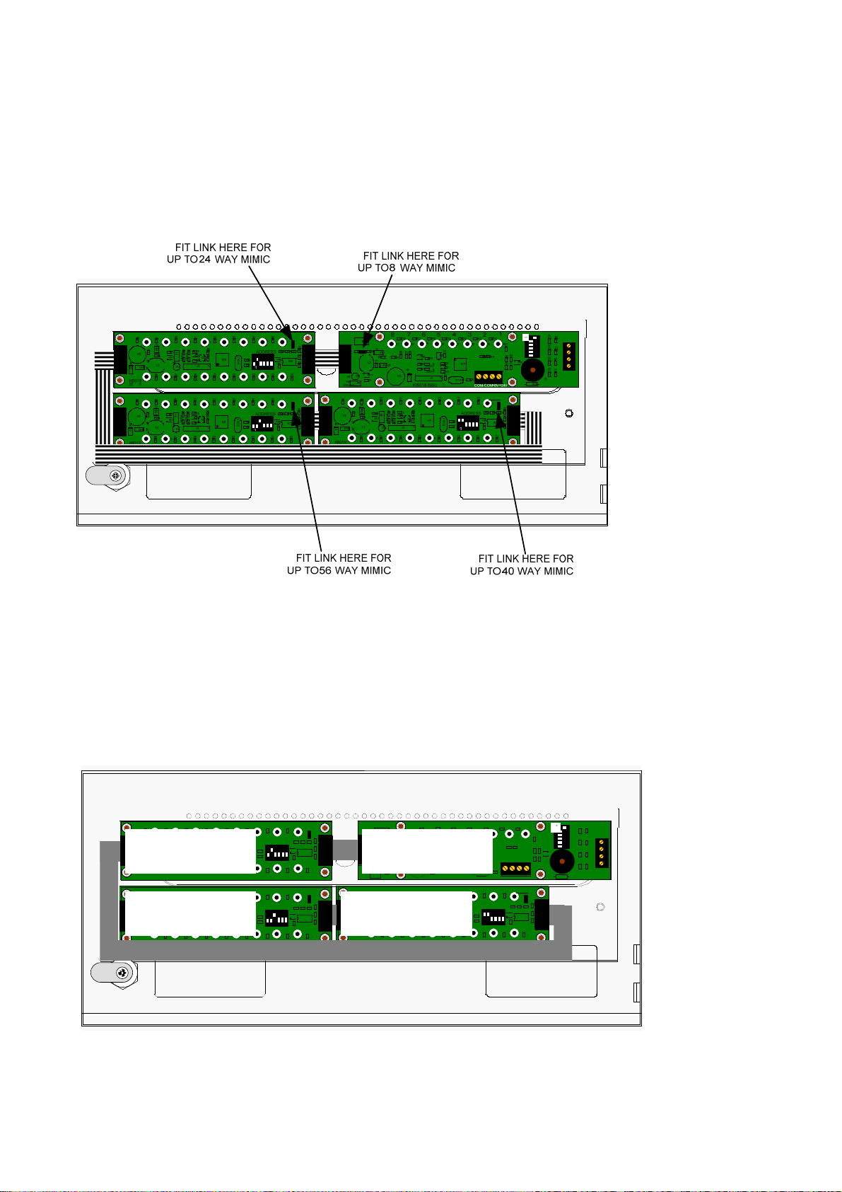
Number of indicators (standard models) up to 8, up to 24, up to 40 or up to 56
5. Common indications and controls
Versions of Syncro Matrix Mimic panels are available with or without common indications and
controls.
Versions with common indicators have the following standard indicators:
FIRE – Lights whenever a fire condition is present on the panel to which the mimic panel is
connected
POWER ON – Indicates that the mimic panel is supplied with power
FAULT- Lights whenever a fault condition is present on the panel to which the mimic panel is
connected
DISABLEMENT - Lights whenever a disablement condition is present on the panel to which the
mimic panel is connected
Versions with controls have the following switches:
ENABLE CONTROLS – Keyswitch which enables the RESET and ALARM SILENCE controls
LAMP TEST – Illuminates all indicators when pressed for testing purposes
BUZZER SILENCE – Silence the mimic’s internal buzzer
RESET – Resets the Syncro control panel to which the mimic panel is connected
ALARM SILENCE – Silences the sounders on the Syncro control panel to which the mimic panel is
connected.
www.acornfiresecurity.com
www.acornfiresecurity.com