Smartswitch FR-8000 User manual

SMARTSWITCH
FR-8000
Fire Alarm Monitor
Installation Manual

Introduction 1
System Components 2
Wiring Block Diagram 3
Connection Diagram for One Sensor 4
Connection Diagram for Multiple Sensors 5
Wiring Block Diagram –Single Engine Room Layout 6
Wiring Block Diagram –Twin Engine Room Layout 7
Wiring Diagram for FR-8000 8
Wiring Diagram for FR-100 9
Connection Diagram for FEC -6 & FEC-1 10
Installation & Electrical Specifications 11
Mounting Instructions 12
System Overview 13
Relay Operations 14
Programming Instructions 15
Programming Instructions Cont. 16
Programming Instructions Cont. 17
Programming Instructions Cont. 18
Operating Instructions 19
Installation Instructions 20
Table of Contents

1
Introduction
Thank you for purchasing the FR-8000 Fire Alarm Monitor. Smartswitch is very proud to be able
to provide this product to you. You have selected a capable system designed to provide years of
reliable service under the most demanding conditions.
Smartswitch is a pioneer in the design and development of distributable intelligence controller
systems for the marine industry. The FR-8000 Fire Alarm Monitor is a versatile, compact,
modern, stylish, user-friendly intelligent network system. Our Research and Development Team
have developed this system specifically for the marine environment using proven techniques
and materials, which will ensure a long life at sea.
The FR-8000 provides features found only in expensive computer-based systems on mega-
yachts, but does so for a fraction of the cost. It is an economical and capable alternative to
simplistic monitoring systems. The FR-8000 allows builders and retrofitters to offer a system
with maximum functionality thereby providing boat owners with excellent visibility into any alarm
condition.
The main features are:
•12/24 volt auto detect.
•Early detection and warning of engine room fire.
•Full machinery shutdown management for up to six devices.
•Fire detection throughout vessel.
•Full monitoring of extinguisher trigger cupboard door.
•Comprehensive fault monitoring.
•Cylinder pressure monitoring.
•Up to 8 zones

2
System Components
FR-8000 Master Display Unit (MDU)
Provides the following functions
•12/24 volt.
•Early detection and warning of engine room fire.
•Full machinery shutdown management for up to six devices (see FEC-6).
•Comprehensive fault monitoring.
•Cylinder pressure monitoring (see FEC-6).
•Latched display for up to 8 Alarms
oAll names are user programmable
oNetwork communication fault
oVisual alarm with tone
FR-100 Input/Output Unit (IOU)
The FR-100 is a controller, which provides 8 Zone Inputs for Smoke Sensors and 1
Output Relay.
•Each Input requires 4K7 end of line resistor for supervised line
•Minimum fault sense current = 8mA
•Output Relay’s
o10 A resistive @ 24VDC
oRelay 1 & Relay 2 close on Fire detection
oRelay 1 opens when alarm is muted
oRelay 2 opens when all zones are OK
FEC-1 Engine Relay Controller
The FEC-1 has one relay.
oOutput Relay 1 = 3 amp inductive
FEC-6 Engine Relay Controller
The FEC-6 has six relays.
oOutput Relay 1 to 4 = 10 A resistive @ 24VDC
oOutput Relay 5 & 6 = 1 A resistive @ 30VDC
Pyro-5 Pyrogen interface module
Monitor and release up to 5 Pyrogen extinguisher bottle’s
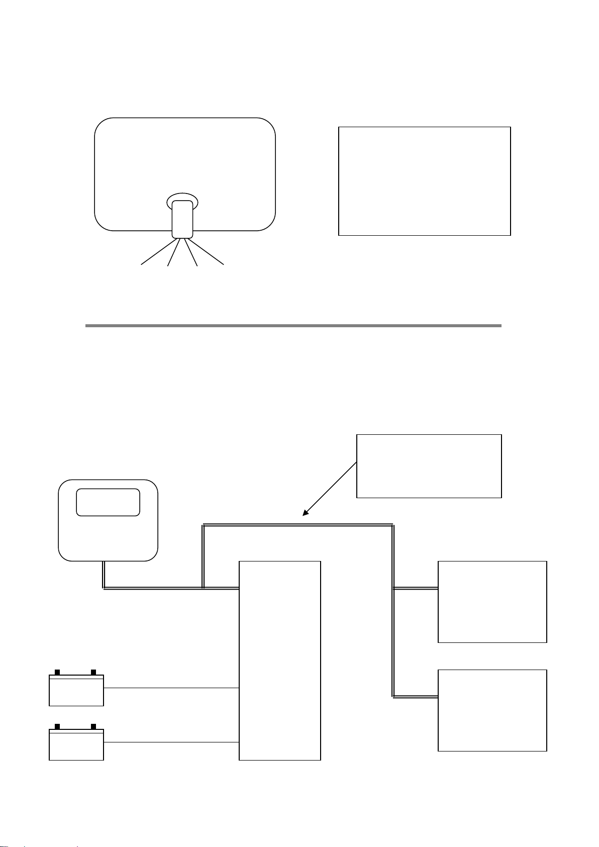
3
Optional FEC - 6
Engine Room Controller
Engine shut down
Fan shut down
Evacuate light
Relays
Relays
4 core cable e.g. cat 5 (max length = 1000m)
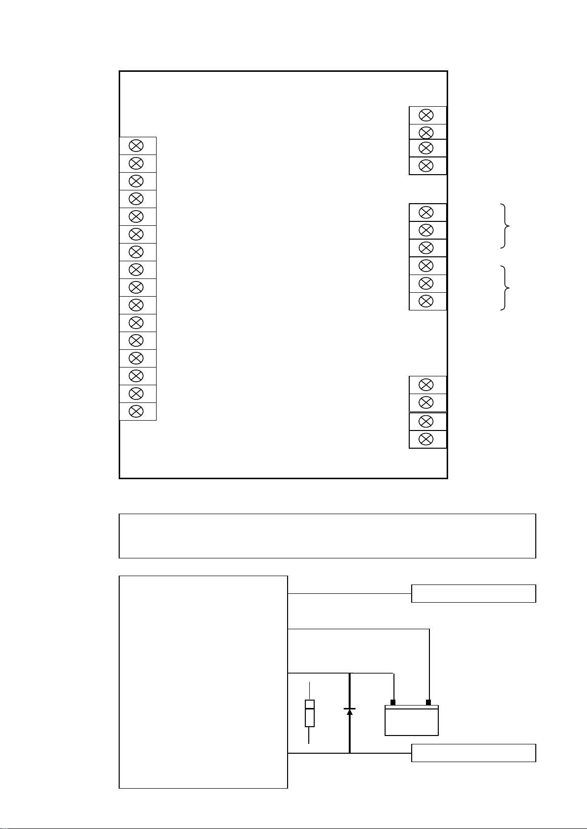
Wiring Block Diagram
FR-8000
Master Display Unit (MDU)
Optional Sensors
Sensor
NOTE:
Sensors must have
4K7 ohm end of line
resistor fitted.
Battery negative
Battery positive
Relay 1
FR-100
(IOU)
Aux battery negative
Aux battery positive
Total Zone
Inputs = 8
Sensor Input Unit
Relay
Single Relay
Unit
Optional FEC - 1
Relay 2
Inputs
+Vdc
GND
Coms +
Coms -

4
Gnd
Input
Connecting One Sensor Per Zone
L or Com –or 6
L1 or In + or 1
L2 or Out+ or 2
R
4K7
4K7 ohm end of line
resistor (EOL).
FR-100
(IOU)
Zone +
Zone -
Wiring for the extinguisher trigger
cupboard door
1k ohm
4K7 ohm
Normally open switch.
Switch closes when door
is opened.
FR-100
(IOU)
End of line resistor
Note: Detector manufactures use different terminal designators,
E.g. L1, L2 , L3 OR Com –, In + , Out + OR 1, 2, 3 ,4, 5, 6
Note: For HOCHIKI brand us terminals 1, 2, & 6

5
R
L or Com –or 6
L1 or In + or 1
L2 or Out + or 2
R
R
FR-100
(IOU)
Connecting Multiple Sensors Per Zone
Note: Detector manufactures use different terminal designators,
E.g. L1, L2 , L3 OR Com –, In + , Out +
4K7 Ohm end of line
resistor (EOL).
Zone +
Zone -
L1 or In + or 1
L1 or In + or 1
L or Com –or 6
L or Com –or 6
L2 or Out + or 2
L2 or Out + or 2
Note: For HOCHIKI brand us terminals 1, 2, & 6
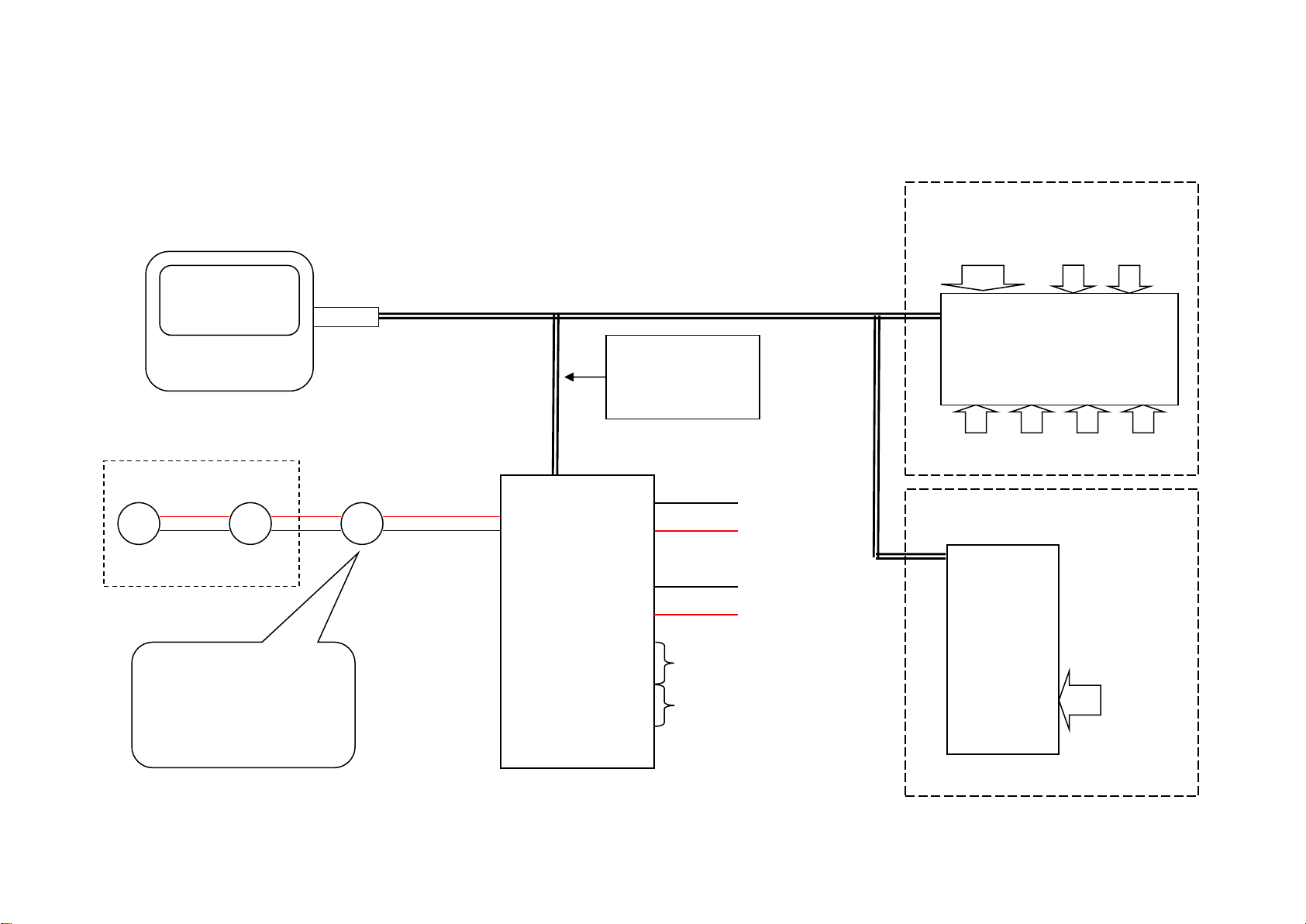
6
Single Engine Room Layout
FR-8000
Master Display Unit (MDC)
FR-100
Zone
Sensor
Input Unit
Relay 1
Relay 2
Sensor
Gas cylinder
release door
switch
FEC-6
Engine
Relay Unit
Relay 1
Relay 2
Relay 3
Relay 4
Relay 5
Relay 6
Gas cylinder
pressure switch
Optional FEC-6 or FEC-1
FEC-1
Relay 1
4 Core Cable
Battery + & Battery -
Coms + & Coms -
Optional: Pyro-5
Pyrogen interface
module
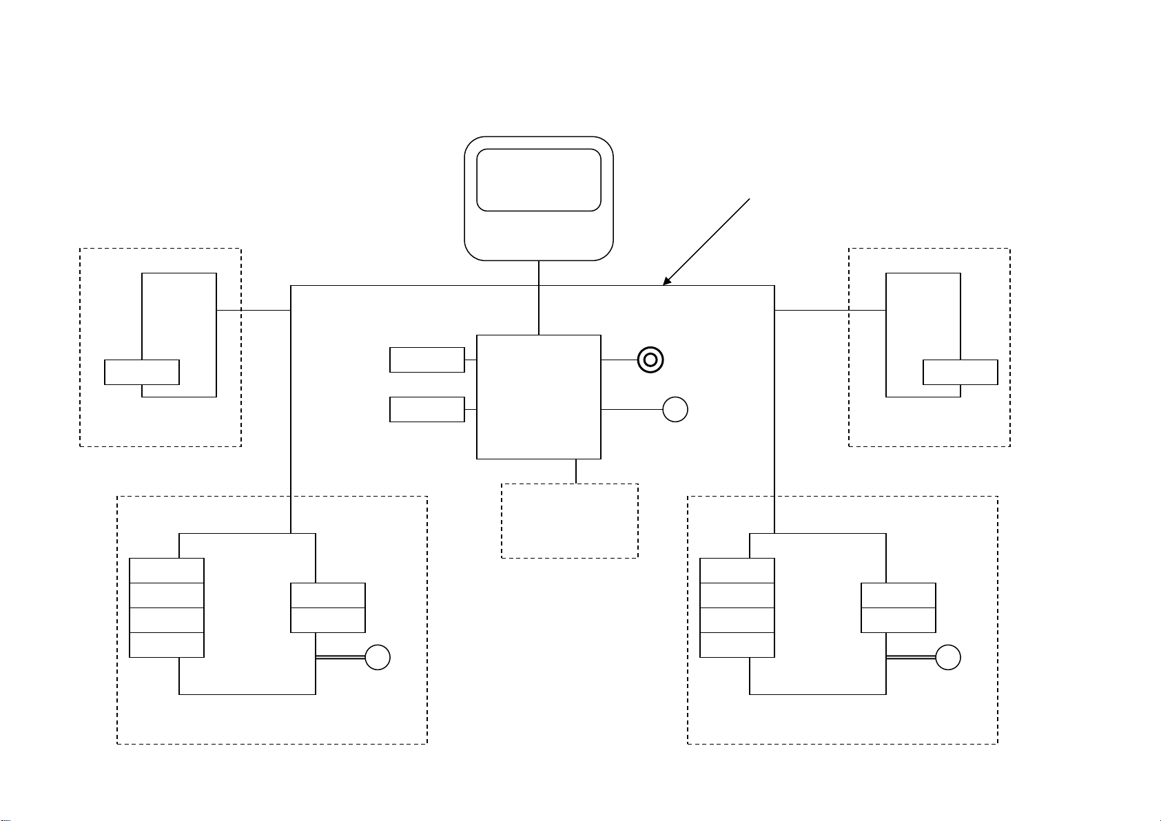
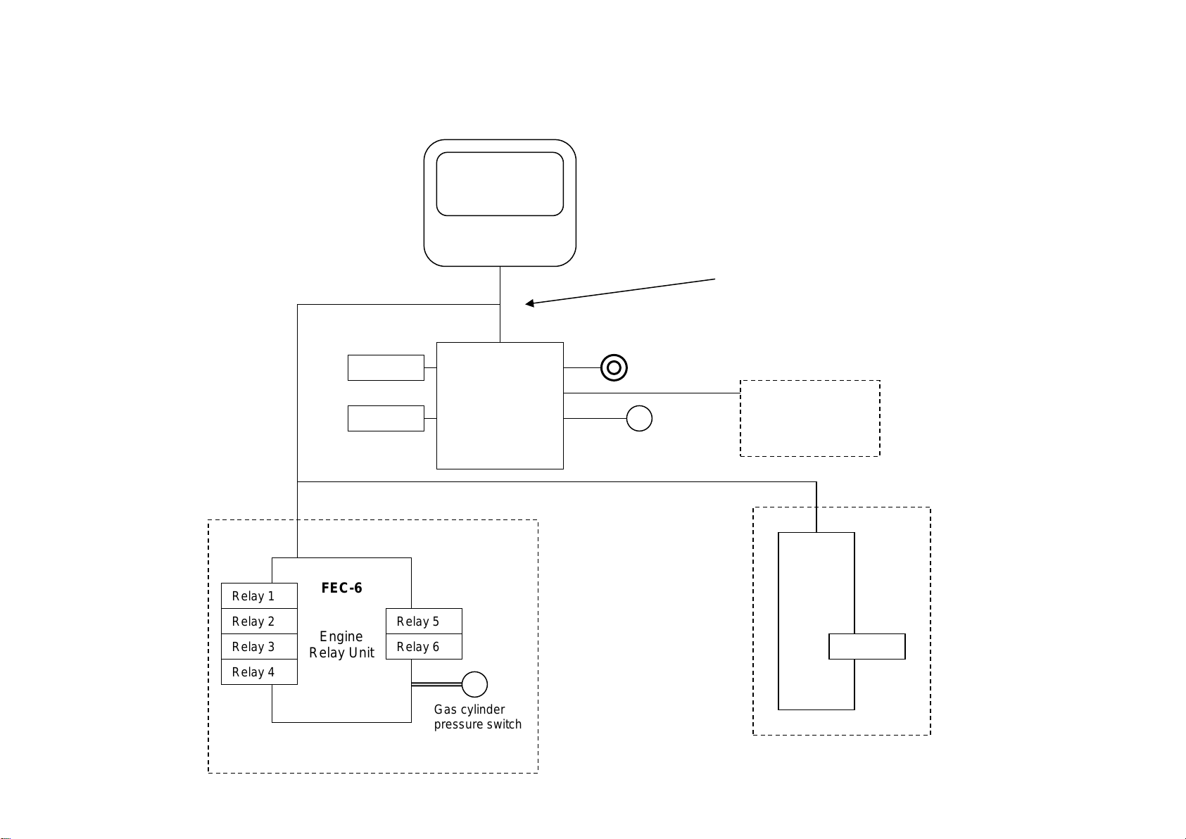
7
Optional FEC-6 or FEC-1
Twin Engine Room Layout
FR-8000
Master Display Unit (MDC)
FR-100
Zone
Sensor
Input Unit
Relay 1
Relay 2
Sensor
Gas cylinder
release door
switch
FEC-6
Engine
Relay Unit
Relay 1
Relay 2
Relay 3
Relay 4
Relay 5
Relay 6
Gas cylinder
pressure switch
FEC-6
Engine
Relay Unit
Relay 1
Relay 2
Relay 3
Relay 4
Relay 5
Relay 6
Gas cylinder
pressure switch
FEC-1
Relay 1
FEC-1
Relay 1
4 Core Cable
Battery + & Battery -
Coms + & Coms -
Optional: Pyro-5
Pyrogen interface
module
Use FEC-1 or FEC-6 optional
Use FEC-1 or FEC-6 optional
8
FR-8000 Display Wiring Connections:
Connections
Red = +Vdc
Black = GND
Blue = Coms +
White = Coms -
Back View
White
Blue
Black
Red
Power and Comms Wiring Connections:
FR-8000
FEC-6
(Optional)
FEC-6
(Optional)
4 Core Cable Supplying
+ Vdc
GND
Coms +
Coms -
+ -
+ -
Aux Battery
Main Battery
FR-100
GND
Com +
Com –
+ Vdc
Out
Aux In
In
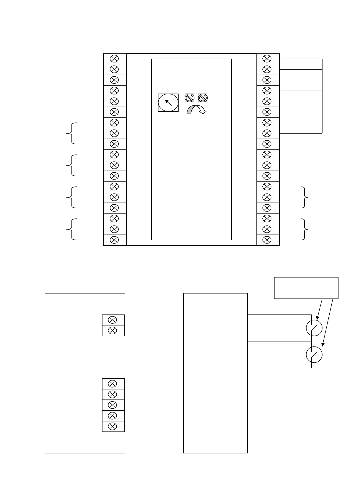
9
Wiring Diagram for Input/Output Unit FR-100
Note: If you require the Aux Battery to be charged by the Main Battery supply
then fit D1charging diode (IN 5404) as per below. The stripped band on the diode
should be connected to the Aux Battery + terminal.
Aux Battery
+ -
To Main Battery +
To Main Battery -
Main Battery +
Aux Battery -
Aux Battery +
Main Battery -
D1
Zone 5 -
Zone 5 +
Zone 6 -
Zone 6 +
Zone 7 -
Zone 7 +
Zone 8 -
Zone 8 +
Zone 1 -
Zone 1 +
Zone 2 -
Zone 2 +
Zone 3 -
Zone 3 +
Zone 4 -
Zone 4 +
+Vdc
GND
N/O
Common
N/C
+ Vdc
Coms -
GND
+ Vdc
N/O
Common
N/C
Coms +
GND
Relay 2
Relay 1
Main Battery +
Main Battery –
Aux Battery –
Aux Battery+
NOTE:
The Rotary Switch on the side
MUST be turned to position 2
10
Connections for FEC-6
1
2
3
4
5
6
7
8
9
10
11
12
13
14
15
16
17
18
19
20
21
22
23
24
25
26
27
28
29
30
31
32
33
34
35
36
Connections for FEC-1
FEC-1
Battery +
Battery -
N/C
N/0
Common
Com +
Com -
GND
+Vdc
N/O
N/C
Com
Relay 4
N/C
N/O
Com
Relay 3
N/C
N/O
N/O
Com
Com
N/C
Relay 2
Relay 1
N/O
Com
Relay 5
N/C
Com
N/O
N/C
Relay 6
Com –
Com +
Input 1
Input 2
Input 3
Input 4
Input Common
Links MUST be
installed
SmartSwitch
Address
FEC - 6
www.smartswitch.co.nz
Rel 2 Rel 3
FEC-6
Inputs
Input Common
Input 1
Extinguisher Bottle
Pressure Switch
Input 2
This can be repeated
for Input 3 and 4.
NOTE: The end of line
resistor is NOT
required for these
Inputs
Inputs for FEC-6

11
Smartswitch recommends that a Qualified Marine or Auto-Electrician install
this product.
Step 1:
Install and connect the Master Display Head Unit (FR-8000).
Step 2:
Install and connect the IOU (FR-100) and connect Sensors.
Step 3:
Install and connect FEC-1/FEC-6 if applicable.
Step 4:
Program the Display Unit (FR-8000).
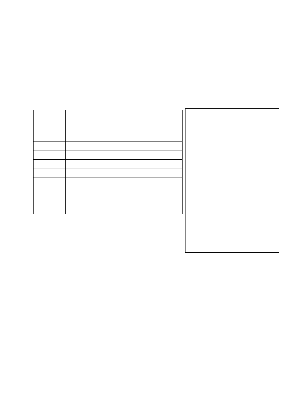
Electrical Specifications FR-8000
Supply Voltage 10 to 30 Volts DC (Auto-Sensing)
Quiescent Current 50mA (backlight off)
Data Retention 50 years (without power)
Electrical Specifications FR-100
Supply Voltage 10 to 30 Volts DC (Auto-Sensing)
Quiescent Curent 30 mA
Min fault sense current 8mA
Relay 1 10 A resistive @ 24VDC
Relay 2 10 A resistive @ 24VDC
Electrical Specifications FEC-1
Supply Voltage 10 to 30 Volts DC (Auto-Sensing)
Quiescent Curent 10mA
Relay 1 3 amps Inductive
Electrical Specifications FEC-6
Supply Voltage 10 to 30 Volts DC (Auto-Sensing)
Quiescent Curent 200 mA
Relay 1 to 4 10 A resistive @ 24VDC
Relay 5 & 6 1 A resistive @ 30VDC
Network Cable
The cable connecting the Display Unit to the Input/Output Units is referred to as the network cable
and may run up to 1000 meters in total length.
Installation Steps
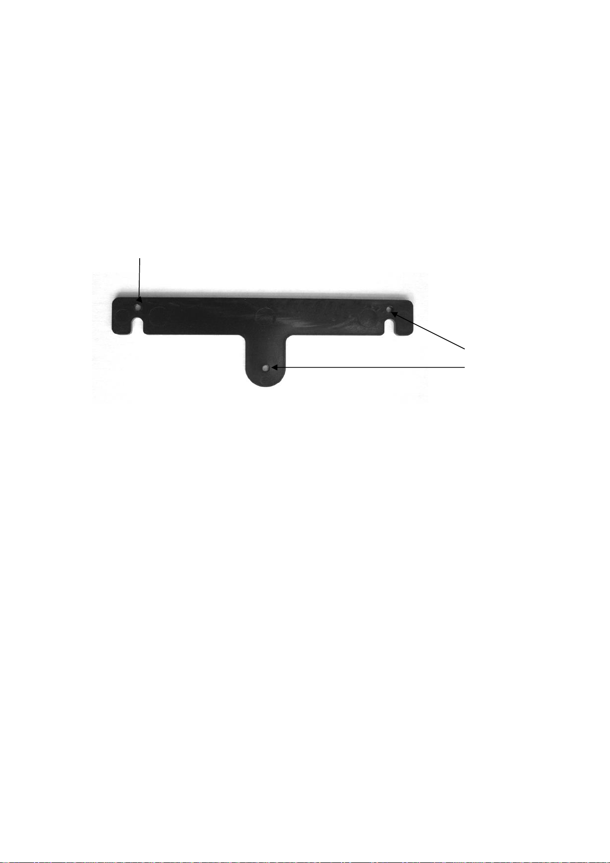
12
Position the mounting template tool provided and mark all three pilot holes. Drill a 3mm hole
on the two outside holes and fit the mounting screws provided. Place the template tool back
over the screws and tighten the screws until the template tool can just slip on and off the
screws (ensure the tool in not too loose).
Drill the bottom hole to 12 mm (cable hole).
Place the Display Unit keyholes over the two screws and gently pull down. If the screws have
been tightened to the correct depth the Display will clip down and self tighten.
Pilot Holes
Pilot Hole
Mounting Instructions
Mounting the FR-8000 Display Unit

13
System Overview
The FR-8000 Alarm Monitor has been developed to allow monitoring of up to 8 zones.
It is a network-based system consisting of a Master Display Unit (FR-8000), a Sensor
Input Unit (FR-100), Smoke Sensors and an optional Engine Room Relay Controller
(FEC-6).
A 4-wire network cable interconnects all devices. The Master Display Unit (MDU) controls
communication with the Input / Output Unit (IOU). System components may be located
anywhere on the network cable and the cable may be up to 1000 meters in length.
Each area which are referred to as zones, can have multiple sensors. An Engine
Room Relay Controller can be fitted (model FEC-6) and any zone can be associated
to that engine relay box.
If there is a fire in a zone associated to the engine relay box - in auto mode it will
automatically shut down fans, fuel pumps and/or any device attached to that relay
box (see page 14 for relay details). In manual mode it will ask you to press the enter
key to start this process.
An extinguisher trigger cupboard door or doors may be connected to a Sensor Input
Unit (FR-100).
This input is fully monitored and if the extinguisher trigger cupboard door is opened
then the alarm buzzer will sound, the Master Display Unit will display ‘Open’ and
relays 5 & 6 will close on the Engine Room Relay Controller (FEC-6) or relay 1 on
(FEC-001). See page 14 for relay details.
The extinguisher bottle pressure switch may be connected to the Engine Room Relay
Controller (FEC-6) see page 10 for details.
This input is monitored and if the extinguisher bottle is empty the Master Display will
display “Empty” if full it will display “OK”
Input 1, 2, 3 and 4 are all internally connected in the FEC-6 so multiple bottles may
be connected. If multiple bottles are connected and one is empty the display will
show “Empty” therefore all bottles will need to be inspected to locate the empty one.
Optional: Pyro-5 Pyrogen interface module
This module will monitor up to 5 Pyrogen extinguisher bottles, also has bottle release
input.

14
Model FEC –6:
An Engine Room Relay Controller can be fitted (model FEC-6) and any zone can be
associated to that engine relay box.
If there is a fire in a zone associated to the engine relay box - in auto mode it will
automatically shut down fans, fuel pumps and/or any device attached to that relay box, in
manual mode it will ask you to press the Ent key to start this process.
When a fire is detected in a zone that has been associated with the engine controller (FEC-6)
and the FR-8000 (MDU) is in Manual Mode the display will show:
When the Ent key is pressed the following will happen on the FEC-6:
Relay 1, 2, 3 and 4 will activate.
Relay 2 and 3 can be delayed by adjusting the trim pot (next to the address select rotary
switch) marked Rel 2 and Rel 3. Rel 2 adjusts the time for Relay 2 and Rel 3 adjusts the time
for Relay 3. Turn Anti-clockwise to increase time.
Relay 2 Min time = 0 seconds, max time = 1 minute.
Relay 3 Min time = 0 seconds, max time = 1.5 minute
Relay 4 has a delay associated to it called the Eng Stop Time, which is setup in the Controller
Menu on the FC-8000 (MDU). When the programmed time has elapsed Relay 4 will activate.
Example: If the solenoid on the extinguisher bottles is connected Relay 4 and the stop time is
set to 30 seconds, this would give a 30 second window for the fans and engine (connected to
Relay 1 & 2) to stop before the extinguisher is set off.
Relay 5 & 6 are associated with the manual extinguisher trigger cupboard door.
If the extinguisher trigger cupboard door is opened Relay 5 & 6 will activate. Relay 6 will stay
activated until the door is closed, Relay 5 will deactivate when the Mute key is pressed on the
FR-8000 (MDU). Example: Relay 6 connected to the evacuate engine room light and Relay 5
connected to a buzzer.
When a fire is detected in a zone that has been associated with the engine controller (FEC-6)
and the FR-8000 (MDU) is in Auto Mode the above will happen automatically.
Model FEC –1:
The FEC-1 is a single Relay unit, which could be used instead of the FEC-6 if only 1 Relay is
required. Example: To turn on the evacuate engine room light.
Model FR-100:
The FR-100 has two relays Relay 1 & Relay 2. Both Relay 1 and Relay 2 will only activate on
Fire detection. Relay 1 will de-activate when the alarm is muted while Relay 2 will stay
activated while Fire is displayed on the MDU.
Relay Operations
ENGINE ROOM FIRE
PRESS ENT KEY TO
STOP ENGINE & FANS
PUSH ISOL TO ISOL

15
Step 1: Placing the unit in Program Mode
Press and hold down the Mute & Select Up keys together for 3 seconds. This will bring you to
the Set-Up Menu and place the unit in program mode.
The display will show:
Scroll to PROGRAM ZONE and press the Ent key.
Step 2: Program Zone
The display will now show:
Use the Select Up or Down key to change the Input number, which corresponds to the Input
being programmed.
Once the Input number has been selected press the Ent key to accept.
Step 3: Selecting /Creating Zone Name’s
The display will now show:
Use the Select Up or Down key to scroll through the pre-named zone names. Once you have
found the one required press the Ent key.
If you would like to create your own name press the Mute key. Use the Select up or down key
to scroll through the alphabet and the Dim up or down key to change to the next character.
When finished press the Ent key.
Programming Instructions
SALOON
Select Alarm Text
Push MUTE to Change
Push ENT to Enter
Select Input 1
Push MUTE to Exit
Push ENT to Enter
SET-UP MENU
PROGRAM ZONE
REMOVE ZONE
EXTINGUISHER DOOR
ENGINE CONTROLLER
ERASE I/O BOX
EXIT MENU
16
For ease of reference please use the chart provided as this will enable quick
reference when programming the zone in the Display Unit.
PLEASE NOTE: You must use a different name for each zone, you can then change
that name but you MUST use a different name each time you program a zone.
Think of it as each zone has a memory look up position and in the memory position
is a name that the zone uses.
Rotary
Switch=2
Zone
Zone
Choose one “Zone name” designation from list
on right USE or CHANGE and record this
below
1
2
3
4
5
6
7
8
Pre-programmed Zone names
•SALOON
•MASTER CABIN
•GALLEY
•ENG ROOM
•AFT WALK THRU
•MACHINE ROOM
•ENG/ROOM PORT
•ENG/ROOM STBD
•MAIL DECK
•UPPER DECK
•LAZZARETTE
•CYLINDER DOOR
•STB CYLINDER
•PORT CYLINDER
•PORT CYL/DOOR
•STB CYL/DOOR

17
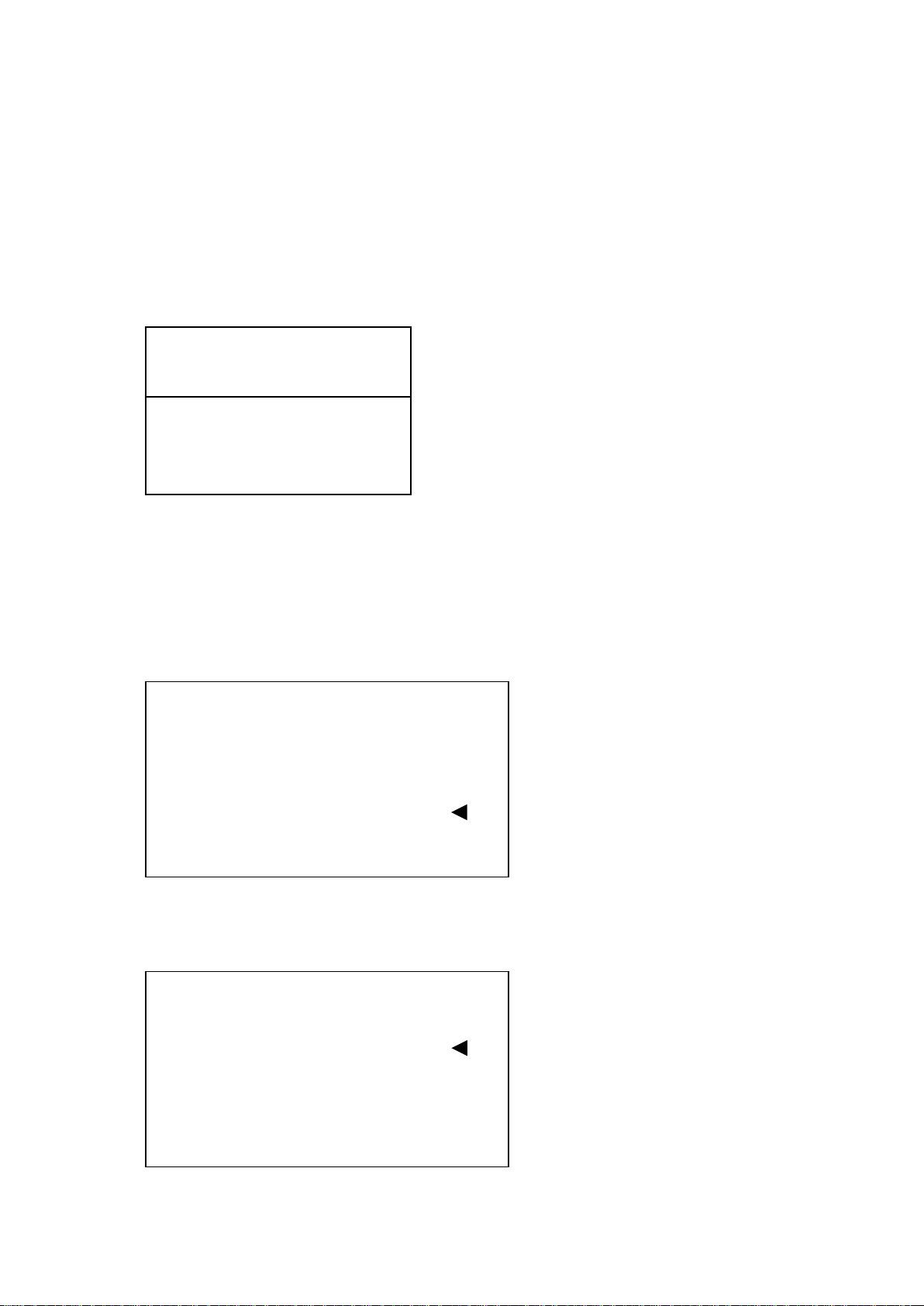
Step 4: Next or End
The display will now show:
Press the Select Up key to set-up the next Input or Select Down key to end and return to the
Set-Up Menu.
REMOVE ZONE:
Zones can be removed by scrolling to REMOVE ZONE, in the Set-Up Menu and pressing the
Ent key.
The display will now show:
Use the Select Up or Down key to change the Input number, until you find the one which
corresponds to the Zone you wish to remove.
Once the Input number has been selected press the Ent key to accept.
EXTINGUISHER DOOR:
If the vessel is fitted with an extinguisher cupboard holding the extinguisher trigger cable, the
door will need to be monitored. From the Set-Up Menu scroll to EXTINGUISHER DOOR and
press the Ent key.
The display will now show:
Use Select Keys
Next End
Select Input 1
Push MUTE to Exit
Push ENT to Enter
SET-UP MENU
PROGRAM ZONE
REMOVE ZONE
EXTINGUISHER DOOR
ENGINE CONTROLLER
ERASE I/O BOX
EXIT MENU
SALOON
Select Alarm Text
Push MUTE to Change
Push ENT to Enter
18
Use the Select Up or Down key to scroll through the pre-named zone names. Once you have
found the one required press the Ent key.
If you would like to create your own name press the Mute key. Use the Select up or down key
to scroll through the alphabet and the Dim up or down keys to change to the next character.
When finished press the Ent key.
You now need to associate the door switch with a relay controller (FEC-6 or FEC-1).
If a FEC-6 is installed Relay 5 & 6 will activate when the extinguisher door is opened. Relay 6
will stay activated until the door is closed, Relay 5 will deactivate when the Mute key is
pressed on the FR-8000 (MDU). If a FEC-1 is fitted the Relay will activate when the door is
open. The zone needs to be associated with either the Port or Stb (FEC-6) engine controller.
If there is only a FEC-1 fitted then you can choose either Port or Stb, as either will work.
The display will now show:
Use the Select Up or Down key to scroll between Port and Stb, (if the vessel is single engine
room then just select Port) and press the Ent key to accept.
ENGINE CONTROLLER:
If a FEC-6 or FEC-1 is installed, scroll down to ENGINE CONTROLLER and press the Ent
key.
You will now see a new Menu. This is the Engine Room Controller Set-Up Menu and is used to
associate a zone with the FEC-6 engine room controller
The system will now display:
SET THE ENGINE BOX
ASSOCATED WITH ZONE
Select Eng I/O Port
Push MUTE to Exit
Push ENT to Enter
SET-UP MENU
PROGRAM ZONE
REMOVE ZONE
EXTINGUISHER DOOR
ENGINE CONTROLLER
ERASE I/O BOX
EXIT MENU
ENGINE CONTROL MENU
SET ZONE
REMOVE ZONE
ENG STOP TIME
AUTO / MANUAL
EXTINGUISHER INPUT
EXIT MENU
Table of contents
Other Smartswitch Fire Alarm manuals

Popular Fire Alarm manuals by other brands

Z-Wave
Z-Wave SF812 user guide

Cooper Notification
Cooper Notification E60H-24MCCH installation instructions

Zeta
Zeta SP-64 User manual, maintenance guide & log book

SMS
SMS SenTRI Data and Installation Instructions

Simplex
Simplex 4002 Life Alarm Service instructions

Summit
Summit SFC-102 Series installation instructions


Aico
Aico Residential Fire Detection RFD Product guide

Ziton
Ziton ZP2 Series Quick operation guide

Johnson Controls
Johnson Controls IFC-1010 Technical manual

Honeywell
Honeywell NOTIFIER AM-8000 Programming manual

Bosch
Bosch FSM-2000 installation guide

System Sensor
System Sensor Innovair SSK451 Installation and maintenance instructions