Vighnaharta TSGR-21 User manual

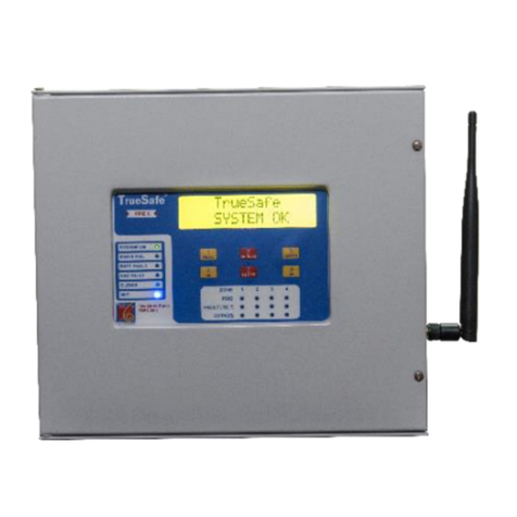
TSGR-21 GAS Release Panel User Manual
Vighnaharta Technologies Pvt. Ltd. Page 1of 43
TRUESAFE GAS RELEASE PANEL
TSGR-21
USER MA NUAL
Mfg. By:
Vighnaharta Technologies Pvt. Ltd.
2nd Floor,Karanjkar Estate,S.N.11/11,Nanded Gaon,Pune-411041
Contact no.: +919011033259 (Landline) Sales: +919011033260
Email: sales@vighnaharta.in | Website: http://www.vighnaharta.in
Vighnaharta Technologies Pvt. Ltd.
2nd Floor,Karanjkar Estate,
S.N.11/11,Nanded Gaon,
Pune-411041
Tel no.: +919011033259, Sales: +919011033260
Prepared By: SSK
Approved By: JVG
Doc No.: TSGR-21_UM_1_0
Rev.No.: 1_0
Eff.Date.: 02.09.2020

TSGR-21 GAS Release Panel User Manual
Vighnaharta Technologies Pvt. Ltd. Page 2of 43
Fire Alarm System Limitations
An automatic fire alarm system—typically
made up of smoke detectors, heat detectors,
manual pull stations, audible warning
devices, and a fire alarm control panel with
remote notification capability—can provide
early warning of a developing fire. Such a
system, however, does not assure protection
against property damage or loss of life
resulting from a fire.
The Manufacturer recommends that smoke
and/or heat detectors be located throughout
a protected premise following the
recommendations of the National Fire
Protection Association Standard 72 (NFPA
72), EN54 Standards, and manufacturer’s
recommendations.
Smoke detectors may not sense fire where
smoke cannot reach the detectors such as in
chimneys, in or behind walls, on roofs, or on
the other side of closed doors. Smoke
detectors also may not sense a fire on
another level or floor of a building. A
second-floor detector, for example, may not
sense a first-floor or basement fire.
Particles of combustion or “smoke” from a
developing fire may not reach the sensing
chambers of smoke detectors because:
• Barriers such as closed or partially closed
doors, walls, or chimneys may inhibit particle
or smoke flow.
• Smoke particles may become “cold,”
stratify, and not reach the ceiling or upper
walls where detectors are located.
• Smoke particles may be blown away from
detectors by air outlets.
• Smoke particles may be drawn into air
returns before reaching the detector. The
amount of “smoke” present may be
insufficient to alarm smoke detectors.
Smoke detectors are designed to alarm at
various levels of smoke density. If such
density levels are not created by developing
fire at the location of detectors, the detectors
will not go into alarm.
Heat detectors do not sense particles of
combustion and alarm only when heat on
their sensors increases at a predetermined
rate or reaches a predetermined level. Rate-
of-rise heat detectors may be subject to
reduced sensitivity over time for this reason,
the rate-of-rise feature of each detector
should be tested at least once per year by a
qualified fire protection specialist.
Audible warning devices such as bells may
not alert people if these devices are located
on the other side of closed or partly open
doors or are located on another floor of a
building. Any warning device may fail to alert
people with a disability or those who have
recently consumed drugs, alcohol or
medication. Please note that:
• Studies have shown that certain people,
even when they hear a fire alarm signal, do
not respond or comprehend the meaning of
the signal. It is the property owner's
responsibility to conduct fire drills and other
training exercise to make people aware of
fire alarm signals and instruct them on the
proper reaction to alarm signals.
A fire alarm system will not operate without
any Electrical power. If AC power fails, the
system will operate from standby batteries
only for a specified time and only if the
batteries have been properly maintained and
replaced regularly.
The most common cause of fire alarm
malfunction is inadequate maintenance. To
keep the entire fire alarm system in excellent
working order, ongoing maintenance is
required as per the manufacturer's
recommendations, and UL and NFPA
standards and EN54 standards. At a

TSGR-21 GAS Release Panel User Manual
Vighnaharta Technologies Pvt. Ltd. Page 3of 43
minimum, the requirements of NFPA 72 or
EN54 shall be followed. Environments with
large amounts of dust, dirt or high air
velocity require more frequent maintenance.
A maintenance agreement should be
arranged through the local manufacturer's
representative. Maintenance should be
scheduled monthly or as required by National
and/or local fire codes and should be
performed by authorized professional fire
alarm installers only. Adequate written
records of all inspections should be kept.
Installation Precautions
WARNING - Several different sources of
power can be connected to the fire alarm
control panel. Disconnect all sources of
power before servicing. Control unit and
associated equipment may be damaged by
removing and/or inserting cards, modules, or
interconnecting cables while the unit is
energized. Do not attempt to install, service,
or operate this unit until manuals are read
and understood.
CAUTION - System Re-acceptance Test after
Software Changes: To ensure proper system
operation, this product must be tested in
accordance with NFPA 72 after any
programming operation or change in site-
specific software. Reacceptance testing is
required after any change, addition or
deletion of system components, or after any
modification, repair or adjustment to system
hardware or wiring. All components, circuits,
system operations, or software functions
known to be affected by a change must be
100% tested.
This System meets NFPA & EN54
requirements for operation However, the
useful life of the system's standby batteries
and the electronic components may be
adversely affected by extreme temperature
ranges and humidity. Therefore, it is
recommended that this system and its
peripherals be installed in an environment
conditions specified.
Verify that wire sizes are adequate for all
initiating and indicating device loops.
Remove all electronic assemblies prior to any
drilling, filing, reaming, or punching of the
enclosure. When possible, make all cable
entries from the sides or rear. Before
making modifications, verify that they will
not interfere with battery, transformer, or
printed circuit board location.
This system contains static-sensitive
components. Always ground yourself with a
proper wrist strap before handling any
circuits so that static charges are removed
from the body. Use static suppressive
packaging to protect electronic assemblies
removed from the unit.
Like all solid state electronic devices, this
system may operate erratically or can be
damaged when subjected to lightning
induced transients. Due to such activity there
may be temporary degradation or damage
occurred. Although no system is completely
immune from lightning transients and
interference, proper grounding will reduce
susceptibility.
Follow the instructions in the installation,
operating, and programming manuals. These
instructions must be followed to avoid
damage to the control panel and associated
equipment. Fire Panel operation and
reliability is depend upon proper installation.

TSGR-21 GAS Release Panel User Manual
Vighnaharta Technologies Pvt. Ltd. Page 4of 43
Abbreviations
TSGR21: TrueSafe Gas Release Panel with 2 Input Zones, 1 Main RAC output, 1 Standby RAC
output.
RAC1: Main Cylinder Output
RAC2: Standby Cylinder Output
IDC: Initiating Device Circuit (for example, Smoke detector(Make - Vighnaharta, Apollo series 65,
GST and Orbis are compatible with TSGR-21) / Heat detector / MCP)
RAC: Releasing Appliance Circuit (for example, FM200)
FM 200: Gas Extinguisher which removes the free radicals or heat element from the fire triangle.
(Oxygen, Heat and Fuel)
NAC: Notification Appliance Circuit (NAC / sounder)
ACK: Acknowledge
MCP: Manual Call Point
RTC: Real Time Clock
PFC: Potential Free Contact
RTU: Remote Terminal Unit

TSGR-21 GAS Release Panel User Manual
Vighnaharta Technologies Pvt. Ltd. Page 5of 43
Table of Contents
Abbreviations.............................................................................................................................................................................4
1. Product Description .............................................................................................................................................7
1.1 Overview:.....................................................................................................................................................................7
1.2 System Features:...........................................................................................................................................................8
1.3 Technical Specifications...............................................................................................................................................9
1.4 Controls and Indications.............................................................................................................................................10
1.4.1 Controls....................................................................................................................................................10
1.4.2 LED Indications.......................................................................................................................................11
1.4.3 LCD Indication ........................................................................................................................................11
1.4.4 Buzzer Indication....................................................................................................................................11
1.5 Components................................................................................................................................................................12
2. Installation .........................................................................................................................................................13
2.1 Installation Precaution................................................................................................................................................13
2.2 Mounting Details........................................................................................................................................................13
2.3 Block Diagram of Panel..............................................................................................................................................14
2.3.1 Field Wiring Details..................................................................................................................................15
2.3.3 Initiating Device Circuit (IDC) ................................................................................................................17
2.3.4 Output Circuits..................................................................................................................................18
2.3.5 Release & Abort controls..................................................................................................................19
2.4 Maintenance ................................................................................................................................................................19
2.4.1 Maintenance mode through Key Switch ...................................................................................................19
2.4.2 Servicing..................................................................................................................................................20
2.4.3 Periodic inspection and test of system......................................................................................................20
2.5 Do’s and Don’ts..........................................................................................................................................................21
2.5.1 Do’s..........................................................................................................................................................21
2.5.2 Don’ts.......................................................................................................................................................22
3. System Configuration ........................................................................................................................................23
3.1 Programming menu: ....................................................................................................................................................23
Press Enter to Default the Panel settings ...........................................................................................................................26
3.2 Program Function:.......................................................................................................................................................26
3.2.1 System Config:..........................................................................................................................................26
3.2.2 Input Config:.............................................................................................................................................27
3.2.3 Output Config: ..........................................................................................................................................28
3.2.4 Event View: ..............................................................................................................................................29
3.2.5 Timer Setting: ...........................................................................................................................................30
3.2.6 Factory Reset: ...........................................................................................................................................31
4. System Operation...............................................................................................................................................32
4.1 Function keys..............................................................................................................................................................32
4.1.1 MENU key...............................................................................................................................................32
4.1.2 ACK key ..................................................................................................................................................32
4.1.3 key: (Left Key)...................................................................................................................................32
4.1.4 SILENCE key ..........................................................................................................................................33

TSGR-21 GAS Release Panel User Manual
Vighnaharta Technologies Pvt. Ltd. Page 6of 43
4.1.5 key: ( Right Key)................................................................................................................................33
4.1.6 Reset Key:................................................................................................................................................33
4.1.7 Enter Key..................................................................................................................................................33
4.1.8 Gas Inhibit:................................................................................................................................................33
4.2 Normal Mode Operation.............................................................................................................................................33
4.2.1 Fire Condition..........................................................................................................................................33
4.2.2 Fault Condition ........................................................................................................................................34
4.2.3 Pre Release Condition..............................................................................................................................35
4.2.4 RAC Released Condition .........................................................................................................................36
4.2.5 RAC Abort Condition ..............................................................................................................................36
4.2.6 System Silence.........................................................................................................................................37
4.2.7 System Reset............................................................................................................................................37
4.3 Zone Disable...............................................................................................................................................................38
4.4 NAC Operation...........................................................................................................................................................38
4.5 RAC Operation...........................................................................................................................................................39
4.5.1 Auto Mode Operation ..............................................................................................................................39
4.5.2 Manual Mode Operation ..........................................................................................................................39
4.6 Keypad Enable, Disable and Evacuate .......................................................................................................................40
4.8 View History Events...................................................................................................................................................40
4.8.1 Fire Alarm Events.....................................................................................................................................40
4.8.2 RAC Release/Abort Events......................................................................................................................41
4.8.3 Fault Events .............................................................................................................................................41
4.8.4 Sequence of Events..................................................................................................................................42

TSGR-21 GAS Release Panel User Manual
Vighnaharta Technologies Pvt. Ltd. Page 7of 43
1. Product Description
1.1 Overview:
TSGR-21 is basically used for fire detection as well as suppression panel to suppress fire using gas
release system. Main purpose of the system is to monitor fire and pressure switch of TSGR-21 gas
release system and if fire is detected, panel will activate the solenoid valve to release the gas
cylinder and display shows the fire zone. This system also has main and stand by gas cylinder
pressure monitoring. In case, the main gas cylinder consumed and gone for refilling then in that
case the stand by gas cylinder will be ready for use by selecting it from menu.
The panel includes local buzzer, LEDs for indications and with LCD display, keypad for manual
operation and configuration. The TSGR-21 allows the flexibility in most fire suppression
application. This TSGR-21 is compatible with smoke detectors and heat detectors that can
continuously monitor for trouble and fire condition.
TSGR-21 has following basic models with extra functionality.
No.
Model Name
Input
Smoke
Zones
Releasing Agent Outputs
Digital Inputs
1
TSGR-21
Two
Two (RAC1 –Main Cylinder,
RAC2 –Standby Cylinder)
Actuator, Pressure,
Release, Abort
2
TSGR-21+ (With
RS485 MODBUS
Output, Cloud
connectivity, USB)
Two
Two (RAC1 –Main Cylinder,
RAC2 –Standby Cylinder)
Actuator, Pressure,
Release, Abort, extra 4
DI

TSGR-21 GAS Release Panel User Manual
Vighnaharta Technologies Pvt. Ltd. Page 8of 43
1.2 System Features:
•Operated on 24 V/3A DC power supply.
•Battery low voltage 23 V DC and battery cut at 22 V.
•Stand by battery backup of up to 24 hrs.
•16 x 2 alpha numeric LCD Display.
•LED indications for various modes on front panel.
•Local buzzer indication for fire, fault, and testing operation.
•4 x 2 keypad for configuration and program the system.
•Real time clock.
•Programmable class B Initiating Device Circuits (IDCs) for smoke detectors & heat detectors.
•Normal fire detection.
•Zone Disable facility.
•Automatic and manual RAC release is available.
•Remote and manual release and abort is available.
•Programmable Releasing Appliance Circuits (RACs).
•Cross zone compatibility.
•Three Notification Appliance Circuits (NACs).
•Three PFC output one Fixed for fire, and two programmable relay for fault, Fire & RAC
released condition.
•External digital inputs for RAC release, abort, and Configurable Remote Input for Remote Fire
and Remote Silence
•Configurable time setting –Manual release time, RAC pre release time, Solenoid off Time,
RAC Abort Time, NAC silence time.
•Auto, Manual, Maintenance Key switch
•Keypad Enable , disable and Evacuate though key switch.

TSGR-21 GAS Release Panel User Manual
Vighnaharta Technologies Pvt. Ltd. Page 9of 43
•More than 200 records history events for fire alarm, fault condition, RAC release or abort
condition, sequence of events.
1.3 Technical Specifications
Power Supply
180 –265V AC, 3A, 60/50 Hz.
Input
Initiating Device Circuit (IDC)
•Voltage:24 VDC
•End of Line:4.7KΩ,1 W
•Digital Inputs: 3 inputs
Indication
Front panel LED indications
•SYSTEM ON
•MAINS FAIL
•BATTERY FAULT
•NAC FAULT
•RAC FAULT
•COMMUNICATION FAIL
•SILENCE
•REMOTE FIRE
•PRE RELEASE
•REMOTE RELEASE
•RAC ABORT
•RAC RELEASE
•Wi-Fi
•FIRE
•FAULT
•AUTO
•MANUAL
•MAINTENANCE
LED Indications for 2 zones
FIRE, SHORT FAULT, OPEN FAULT, DISABLE
16 x 2 LCD Dot Matrix Display Indication
Zone fire status, fault status, configuration menus, real time
clock

TSGR-21 GAS Release Panel User Manual
Vighnaharta Technologies Pvt. Ltd. Page 10 of 43
Buzzer Indication
Fire, Fault, Key press acknowledge
Output
Releasing Appliance Circuit (RAC1, RAC2)
Voltage: 24 VDC, Current: 500mA each.
Notification Appliance Circuit (NAC1, NAC2, NAC3)
Voltage: 24 VDC, Current: 250mA each.
PFC Relay outputs: 3
Dimensions
(365 x 90 x 327) mm (L x W x H)
Operating
Temperature
0℃~+50℃
Humidity
5 to 95% Rh
Enclosure
Mild Steel (thickness 1.2mm) with powder coating,
Colour:RAL7035
1.4 Controls and Indications
1.4.1 Controls
Key name
Key function
MENU
•Shows all system menus.
•Configures system as per requirements.
•Can view history events.
•Goes back to previous screen.
•Exits from the menu i.e. ESC.
ENTER
•Access the new menu.
•Saves configured data, mode or value of the system.
SILENCE
•Silence the NACs.
ACK
•Acknowledge the system.
•Put OFF local buzzer.
RESET
•Reset all the system
•Moves cursor of LCD right with the use of key.
•Moves cursor of LCD left with the use of key.
•Moves cursor up with the use of keys.
•Use to increment Count From 0 to 9
•Moves cursor down with the use of keys.
•Use to decrement Count From 9 to 0

TSGR-21 GAS Release Panel User Manual
Vighnaharta Technologies Pvt. Ltd. Page 11 of 43
1.4.2 LED Indications
There are different LED indications given on front panel of gas release system provided to user to alert from
different events occurred. Name of events along with colour of corresponding LED with description are as follows.
1.4.3 LCD
Indication
The 16 x 2 LCD
DOT matrix
display is used
in this TSGR-21
system to
display different
system fault
status, zone fire status, configuration menus, real time clock and so on. The LCD is mainly used for the
programming of the panel listed as below.
•Zone modes
•RAC configuration
•Pre release / remote release time set
•View history events
•RTC settings
•In idle mode, it shows current zone status, date, time
1.4.4 Buzzer Indication
A buzzer provides separate and distinct sounds for Fire and Faults.
•Fire: Continuous Buzzer ON.
•Fault: 1 sec ON and 2 sec OFF.
No.
Indication
LED Colour
Description
1
System ON
Green
This indication shows system is Power ON
2
Mains Fail
Yellow
When Mains Fail Occurs, ON
3
Battery Fault
Yellow
When Battery is Low, ON
4
NAC Fault
Yellow
NAC Fault has been occurred, ON
5
RAC Fault
Yellow
When RAC fault occurs, ON
6
Comm. Fail
Yellow
NA for TSGR-21
7
Silence
Yellow
System has been silenced, ON
8
Remote Fire
Red
Remote Fire Initiated, ON
9
Pre Release
Yellow
Pre Release time has been started, ON
10
Remote Release
Yellow
Remote/Ext. Release is taking place, ON
11
RAC ABORT
Yellow
When RAC operation aborted, ON
12
RAC Release
Yellow
RAC Release is taking place, ON
13
Twin Fire
Red
If any zone is in fire condition, ON
14
Fault
Yellow
If any system fault occurs(short/open), ON
15
Auto
Yellow
Auto Mode , ON
16
Manual
Yellow
Manual mode, ON
17
Maintenance
Yellow
Maintenance mode, ON
18
Zone1 Fire
Red
If zone1 in fire condition, ON
19
Zone1 Short
Yellow
If zone1 Short, ON
20
Zone1 Open
Yellow
If zone1 Open, ON
21
Zone1 Disable
Yellow
If zone1 Disable, ON
22
Zone2 Fire
Red
If zone2 in fire condition, ON
23
Zone2 Short
Yellow
If zone2 Short, ON
24
Zone2 Open
Yellow
If zone2 Open, ON
25
Zone2 Disable
Yellow
If zone2 Disable, ON

TSGR-21 GAS Release Panel User Manual
Vighnaharta Technologies Pvt. Ltd. Page 12 of 43
•Key press acknowledge.
1.5 Components
PCB Board: Consists of CPU, keypad, Display, zones, inputs, and outputs.
Power Supply: 24V, 3 A power supply with each TSGR-21 panel, mounted inside enclosure.
Enclosure: Metallic enclosure with powder coating RAL 7035, size as mentioned in Technical Specifications.
Battery: 24V, 7.5Ah sealed Lead acid battery (optional).
EOL Resistor:
•4.7k ohm 1W Resistor is connected in parallel with each input zones for sensing purpose.

TSGR-21 GAS Release Panel User Manual
Vighnaharta Technologies Pvt. Ltd. Page 13 of 43
2. Installation
2.1 Installation Precaution
WARNING:
Do not attempt to install, service, or operate this unit, until this manual is read and understood. Do not connect
other equipment to this unit.
CAUTION:
This system works at 0° C to +50° C and at a relative humidity of 5 to 90 ±2% RH.
However, the useful life of the system's standby batteries and the electronic
components may be adversely affected by extreme temperature ranges and
humidity.
2.2 Mounting Details
Backside of the panel

TSGR-21 GAS Release Panel User Manual
Vighnaharta Technologies Pvt. Ltd. Page 14 of 43
•Place the panel in its mounting position and fix the panel to the wall using the slots of the three screws.
•Ensure the enclosure and the inner parts of the panel are given sufficient protection during installation.
•Enter all external cables via the 10 numbers of preformed knockouts located at top of the panel.
•When the installation of all the cables has been completed, clean the interior of the enclosure ensuring all
machinery debris and drilling swords are removed.
2.3 Block Diagram of Panel
The following diagram shows basic components of TSGR-21 system. It consists of various smoke and heat
detectors, AC power source, Notification devices like NAC or sounder, Fire Suppression and Releasing agent Gas
based extinguishers, SCADA communication cables, all connected to control panel.
NOTE: Connect all EOL of 4.7K ohms
WARNING:
Several different sources of power can be connected to this panel. Disconnect all sources of power before
servicing. The panel and associated equipment may be damaged by removing and / or inserting cards, modules
or inter connecting while this unit is energized.
Primary Power source (AC) and Earth Ground Connection:
AC Power connections are made inside the control panel cabinet. A separate Earth Ground connection must be
made to ensure the proper panel operation and lightening and transient protection.
Standby Power Source (Batteries):

TSGR-21 GAS Release Panel User Manual
Vighnaharta Technologies Pvt. Ltd. Page 15 of 43
Use two 12V,7Ah sealed lead acid type Batteries. Observe polarity when connecting the battery. Connect the
battery to the provided cable. The battery charger is current - limited and capable of recharging sealed lead acid
type batteries up to 6Ah.
2.3.1 Field Wiring Details
The following diagram shows connector’s placement on Interface board.
Interface board
Connectors and their connections are mentioned in the following table.
Pin No.
Connection
Name
Description
Power Supply System
J1.1
B +
+Battery charging voltage from power supply
J1.2
B –
Battery charging ground from power supply
J1.3
BAT_-
Battery charging ground connection to battery
J1.4
BAT_+
Positive Battery charging connection to battery
J1.5
MF+
Mains Fail Input(+)( Not in Used)
J1.6
MF-
Negative(-)( Not in Used)
J1.7
V+ I/P SUPPLY -
DC Input Supply from SMPS(+)
J1.8
V- I/P SUPPLY -
Ground(-)
Resettable Power Supply
J12.1
RST-24 +
Resettable 24V output Positive (+)
J12.2
RST-24 -
Resettable 24V output Negative (-)
NAC1 & NAC2 & NAC3

TSGR-21 GAS Release Panel User Manual
Vighnaharta Technologies Pvt. Ltd. Page 16 of 43
Pin No.
Connection
Name
Description
J11.1
NAC 1 +
NAC1 Positive(+)
J11.2
NAC 1 -
Ground/NAC1 Negative(-)
J11.3
NAC 2 +
NAC2 Positive(+)
J11.4
NAC 2 -
Ground/NAC2 Negative(-)
J11.5
NAC 3 +
NAC3 Positive(+)
J11.6
NAC 3 -
Ground/NAC3 Negative(-)
RAC1
J14.1
RAC1+
RAC1 Positive(+)
J14.2
RAC1-
RAC1 Negative(-)
RAC2
J14.3
RAC2+
RAC2 Positive(+)
J14.4
RAC2-
RAC2 Negative(-)
Smoke Detector Zones
J3.1
Zone1+
Zone1 Positive(+)
J3.2
Zone1-
Zone1 Negative(-)
J3.3
Zone2+
Zone2 Positive(+)
J3.4
Zone2-
Zone2 Negative(-)
PFC Outputs
J13.1
NO
Normally Open of Fire Status Output
J13.2
C
Common for Fire Status Output
J13.3
NC
Normally Closed of Fire Status Output
J13.4
NO
Normally Open of Prg. Relay1 Status Output
J13.5
C
Common for Prg. Relay1 Status Output
J13.6
NC
Normally Closed of Prg. Relay1 Status Output
J13.7
NO
Normally Open of Prg. Relay1 Status Output
J13.8
C
Common for Prg. Relay1 Status Output
J13.9
NC
Normally Closed of Prg. Relay1 Status Output
Digital Inputs
J4.1
Rel.
Input for RAC1 Release
J4.2
GND
Ground
J4.3
Abort
Input for RAC1 Abort
J4.4
PS.1
Input for Pressure1
J4.5
GND
Ground
J4.6
PS.2
Input for Pressure2
J4.7
ACT.1
Actuator Input 1
J4.8
GND
Ground
J4.9
ACT.2
Actuator Input 2
J4.10
Rmt. I/P +
Digital Remote Input+
J4.11
Rmt. I/P -
Digital Remote Input-
J4.12
DI 1
Extra Digital Input 1 (Not used)
J4.13
DI 2
Extra Digital Input 2 (Not used)

TSGR-21 GAS Release Panel User Manual
Vighnaharta Technologies Pvt. Ltd. Page 17 of 43
Pin No.
Connection
Name
Description
J4.14
GND
Ground (Not used)
J4.15
DI 3
Extra Digital Input 3 (Not used)
J4.16
DI 4
Extra Digital Input 4 (Not used)
Add-on Supply
J15.1
24+
Add-on DC supply Positive(+) (Not used)
J15.2
24-
Add-on DC supply Negative(-) (Not used)
RS-485
J15.3
D+
RS485 D+ (Not used)
J15.4
D-
RS485 D- (Not used)
J15.5
RM_IN
Remote monitoring Input + (Not used)
J15.6
GND
Ground (Not used)
Modbus Communication
J15.7
D+
Modbus D+ (Not used)
J15.8
D-
Modbus D- (Not used)
2.3.3 Initiating Device Circuit (IDC)
•No. of Initiating circuit : 2 Zone
•Type : Class B
•Wire Size : 1.5 sq. mm max.
•Operating Voltage : 27.5 VDC nominal max
•Connector : J3
•Total No. of Devices : 20 smoke detectors per zone
•Monitoring Device : 4.7k ohm, 1 W(EOL)
All zones may be configured for general fire alarm or can be disabled.

TSGR-21 GAS Release Panel User Manual
Vighnaharta Technologies Pvt. Ltd. Page 18 of 43
2.3.4 Output Circuits
The panel has three types of output circuits.
•Notification Appliance Circuit (NAC)
•Releasing Appliance Circuit (RAC)
•Potential Free Contact Relay Outputs (PFC)
NAC
•No. of NAC : 3 circuits
•Type : Class B
•Output Voltage : 27.5 V max
•Current : <250mA (each)
•Terminals : J11
•Wire Size : 1.5 Sq. mm.
RAC
•No. of RAC : 2 circuits
•Type : Class B
•Output Voltage : 27.5 V max
•Current : 500mA (each)
•Terminals : J14
•Wire Size : 1.5 Sq. mm. Twisted pair wire
Fixed Output (PFC)
Four PFC outputs: J13 on Interface board has 9 pins.

TSGR-21 GAS Release Panel User Manual
Vighnaharta Technologies Pvt. Ltd. Page 19 of 43
1. Fire status output (J13.1 –NO, J13.2 –C, J13.3 - NC)
2. Prg.Relay1 status output (J13.4 –NO, J13.5 –C, J13.6 - NC)
3. Prg.Relay2 status output (J13.7 –NO, J13.8 –C, J13.9 - NC)
2.3.5 Release & Abort controls
2.4 Maintenance
2.4.1 Maintenance mode through Key Switch
It is maintenance purpose mode. There is provision in TSGR-21 panel that user can select maintenance
mode by using Key Switch. Remember without key you cannot change the mode. When panel is set as a

TSGR-21 GAS Release Panel User Manual
Vighnaharta Technologies Pvt. Ltd. Page 20 of 43
Maintenance Mode it gets visualized using LED for it. This mode is used to test smoke detector and NAC /RAC is
not get activated.
Maintenance mode Procedure
•First panel is set as Maintenance Mode.
•Then give smoke to the sensor.
•The sensor will detect smoke and LCD will display show fire to the particular zone.
•In this way multiple sensors in a single loop can be tested.
Note: Repeat Maintenance Mode after every 3 months.
2.4.2 Servicing
Following are the servicing check list of TSGR-21 panel. Maintenance / servicing is required twice a year for each
panel.
Sr.
No.
Check point or maintenance point
OK/Not
OK
Remark
1
Before Maintenance / Servicing please evacuate / clear all
the premises
2
Clean each smoke detector using soft cloth.
3
Check panel operation on battery backup mode (mains
OFF).
4
Check panel operation on mains supply (Battery
disconnected).
5
Check all connection of panel.
6
Check Smoke Detector.
7
Check NAC output.
8
Check battery supply.
9
Check panel mounting screw.
Note: Please send above servicing report after every 6 months.
2.4.3 Periodic inspection and test of system
For additional information on control panel faults, regular checking of the functionality of the control panel and fire
detection system by a person responsible for fire prevention in the company must ensure the availability of the fire
detection system.
Weekly Testing By The User
▪Ensure that all indicators are showing correctly.
▪Check that the internal buzzer are operating correctly.
▪LCD Display shows messages from the system.
Table of contents
Other Vighnaharta Fire Alarm manuals
Popular Fire Alarm manuals by other brands

INIM Electronics
INIM Electronics Praesidia series GUIDE TO NETWORKING

FIREGUARD GLOBAL
FIREGUARD GLOBAL FG-S01_AP quick start guide

Myalarm
Myalarm D1256 user guide

Mircom
Mircom MPS-800MP Series manual

FireClass
FireClass FC503 user manual

Potter
Potter PFC-6075RB Installation, operation, & programming manual

Honeywell
Honeywell NOTIFIER ONYX FirstVision Installation and operation manual

Siemens
Siemens FS720 Series Commissioning, Maintenance, Troubleshooting

Siemens
Siemens FDM223 Technical manual

AMG-Sicherheitstechnik
AMG-Sicherheitstechnik BMS 03 user manual

Panasonic
Panasonic Firetracker FT1020G3 CIE Technical and Programming Manual

Spectrex
Spectrex SharpEye 40/40 Duct Mount installation manual