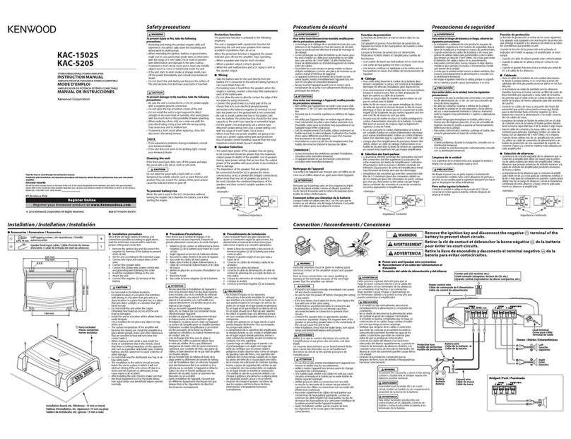
Kenwood KAC-8020 User manual

KACB020
«KENWOOD
TRIO-KENWOOD
CORPORATION
SERVICE
MANUAL
C
1986-3
PRINTED
IN
JAPAN
B51-1955-00(O)
1928
Heat
sink*
(FO1-)
KAC
-B8020
A
PRODUCT
OF
ADVANCED
REBEAREH
NTO
APRLIED
ELECTRONICS
ANO
THE
HUMAN
Y
REGPONSE
TO
BOUND
PHENOMENA
/
BULT
TO
KENWOOD
Tne
PAIS
CRONE
OF
ENGIECRAG
OMEN
STEREO
MAIN
AMPLIFIER,
Panel
*
Foot
(A29-)
(JO2-0183-08)
Connector
Fuse
Slide
switch
Cylindrical
receptacle
(DIN)
(E03-0080
-08)
(F05-2038-05)
{S31
-4021-08)
(E06-0809-08)
|
|h
—>_—=
———
Rear
panel
Terminal
board
Potentiometer
(A23-3190-08)
(E20
-0457-08)
(R29-3021-08)
*Refer
to
parts
list
on
pap
6.

KAC-8020
DISASSEMBLY
FOR
REPAIR
Disassembly
as
follow
(NO.
@
to
®).

KAC-8020
KAC-8020
BLOCK
LEVEL
DIAGRAM
ADJUSTMENT/REGLAGE/ABGLEICH/PACKING
5
ADJUSTMENT
a
5
INPUT
OUTPLT
AMPLIFIER
ALIGNMENT
eal
°
|
ITEM
SETTINGS
SETTINGS
SETTINGS
POINTS
ALIGN
FOR FIC.
|
IDLE
Connect
a
DC
VR101
(L)
!
1
CURRENT
voltmeter
to
TP,
VOLUME:
0
VR201
(R)
12nV
(a)
2
|
E
es
pee
as
|
S
2
b
|
REGLAGE
REGLAGE
DE
REGLAGE
DE
REGLAGE
DE
POINTS
DE
ee
3
ITEM
L°
ENTREE
LA
SORTIE
L'AMPLIFICATEUR
|
L*
ALIGNMENT
ALIGNER
POUR
|
FIG.
a
A
CL
Ze
oO
be
OF
e)
co
“4
w
COURANT
DE
-
Connecter
un
VR101
(C)
81
5G
al
2
POLARISATION
voltmétre
de CC
au
TP,
VOLUME:
0
R201
(D)
b=
oa
3)
c
PARATOR
(Va)
COM-
ABGLEICH
|
EINGANGS-
AUSGANG-
VORSTARKER-
ABGLEICHE-
S
|
ui ti
GEGENSTAND
EINSTELLUNG
EINSTELLUNG
EINSTELLUNG
PUNKTE
ABGLEICHEEN
FUR
ABB,
3
ia
fc
o
|
oS os
Einen
Gleichspannungs-
oS os
LEERLAUF-
messer
zu
TP
VOLUME:
0
VR101
(L)
|
LO zo
STROM
anschlieBen,
VR201
(R)
¥
|
a
a
a|
°
|
#
7
PACKING
=
a
ACK
5
=
[og
Protection
bag
(H25-0112-04)
w
Screw
set
eg
|
>
(N99-0234-08)
Instruction
manual*
(B50-)
ie
ra
. .
Warranty
card*
(B46-)
=
oO
ae
>
5
2
|
B
Polystyrene
foamed
fixture
28
3
R
(H10-1886-08)
Gordaa’y
wes
|
g
(E30-1433-08)
_
By
eee
1
|
{e)
FE
=
S$
|
“”
5
(x)
°
oS
wy
=
‘a
|
:
rs)
ae
+
)
=
|
ts)
Protection
bag
iad
eee
ieee
(H25-0173-04)
;
|
<x
w
iva
ea
4
wy
N
8
&
<
a)
Ooze
ne
|
=
Zor
z}/o8s
928]
ze]
Sliss
ase
FOS
g|Zz2
Ba218
"|
Eo
>
5
|
ke
a
5
|
O
|
Fs)
Item
carton
bow*
b
WT
i
(HO1-)
g
38
»
28
2
25
+
o
*Refer
to
parts
list
on
page
6.

PC
BOARD
KAC-8020
KAC-8020
206
DC
DC
CONVERTER
(WO2)
(B/6)
Foil side
view
POWER
IN
B
ec
a5
32V
16.5V
as
|
siv_
|
3av
a7
35.5v.
|v
as.
|
23v.
|
38.5V
Q9—012
—1.4V
15.3V
13.014.
—1.45V
14.3V
Q15
13.6V
14.1V
aie
|
07v
ov
W02
(B/6)
1C1
W02-0706-08
(A/6)
1c2
FUSE
(W02)
(F/6)
Foil
side
view
wo02
(C/6)
Ic3
©
a
a
So
=
|
ae
|
wi
§
INDICATOR
(W02)
o3
(E/6)
Foil
side
view
0
—|
>
OF
a
|
eK
>
a
DC
voltmeter
=
(ta)
a
ooo00c00
a
go
re
ee
ey
-
(a)
12mV
5
FRONT
=
e—
(?p)
:
a
FONeS
AMP
(W02-0706-08)
7,
A/6)
Foil
side
view
PRE
AMP
(W02)
(C/6)
Foil side
view
KAC
-
8020
Refer
to
the
schematic
diagram
for
the
values
of
resistors
and
capacitors.
Rch
Lch
LSPEAKERSA

VRI
(1/2)
20K
(B)
c102
0,001
R104
20K
R204
20K
VRI(1/2)
C202
0.001
R400
R402
2.4K
2.4K
c
400
100p
10
C303
0,27
eS
ee
ee
ee,
3
a
a
bey
R300
R302
100p
10
2.4K
2.4K
w02-0706-08
(A/6)
ee
Le
R229
220
IC
6
(1/4)
v
RIO6
9.1K
R206
9.1K
Ov.
@
OC
voltages
are
as
measured
with
a
high
impedance
voltmeter
with
no
signal
input.
Values
may
vary
slightly
due
to
variations
between
individual
instru-
ments
or/and
units.
2SA970
2SA817A
2S8C3708
2SC2655
Qe
Ka
28C3854
~C
B
Sc
E
2SA1490
2S
B829
C120
10p1é
CHS
=
R108
0.2
100n10
2k
+
C107
100p
10
ClO
0.033
10
1/2W
C220
10plé
RiUl4@
75K
C8
p50
KR
<
=
°.
m
6
KR
vt
R214
75K
C218
1p50
Ny
C219
0,047
C213
0,0
D204
20,
34
10010
C210
0,033
Z
+
C218
R208
1oopi0
«=
2K
Yoav
CHE
1150
C7
0.047
C406
100p10
R53
510
vow
RI7
33K
PROTECTION
Lav
c50
0.01
R22
20K
Cll
0,01
Ici
¢
MN3102
Q2,13,14
:
28C3708(s)
Qs
1c2
:
pPC1237H
Q4
>
2SA1048(GR)
Q102,
202
:
284970
(GR)
>
28C3421(y)
Ic3
>
NJM2068D-D
Q5
:
288
829(Q,R,S)
Q103,
203
:
25C3854(Y,0)
1c4,5:
pPCI270H
Q6
1
28C2655(yY)
Q104,204
|
2SA1490(Y,0)
Ic6
:
NJM20580
Q7
1
2SABITACY)
Q105,205
:
28C2458(GR)
08,16
1
28C2458(GR)
Q9~12
1
2$01062(s)
2SA1048
2803421
2SD1062
NJM2068D-D
NJM2058D
uPC1237H
28C2458
8
ae
09
DIO
R35
1
1/2W
+
Z
18
4700"
40
i
+
ci7
bay
3300p
40
(eee
uo
s
pI
C4
C13
0.047
}0.047
:
C53
2200p
35
Ju
,
<
wo2
‘
(E/6)
:
B30-1120-08
C7
Z04,5
:
Hz982
LED!
06
:
:
CTU-12R
+
GU-3SY
014
55
207
:HZ5C-1
DI5
:
UB-152
A
08
:RM4Z
016,
17
RHIZ
LED!
D9,10
:
vo3c
D103,
104,203,204
:1N4002
012,13:
CTU-12S
DIO5~107,
205~207
|
IS2076A
—_
—
DI9,20
:
IN4002
;
2018
-HZ5C3
KAC
—
8020
(E)
MN3102
uPC1270H
KAC-8020
NEN
Ol0)B

EXPLODED
VIEW
KAC-8020
|
KAC-8020
>»
New
Parts
PA
RTS
L
l
ST
Parts
without
Parts
No.
are
not
supplled.
Les
articles
non
mentionnes
dans
le
Parts
No.
ne
sont
pas
fournis.
Telle
onne
Parts
No.
werden
nicht
gellefert.
Ref.
No.
Address
|New
Parts
No.
Description
Parts,
SmRES
(ft
©
¥
8B
&
£
8
BA
ASR
KAC-8020
3)
rea’
a
TIN
wba
SoS
72I
SUBWOOFER
“
A
M3x14
:
N30
-
3014
-45
B
M3x10
(F)
+
N32-
3010-46
C
M3x4
1
N30
-
3004-46
@
3x6
=
(Bi-
Top)
:
NO9-
1670-08
M4x12~
(Bi)
BLK
:
NO9-
1598-08
F
M3x8
(Bi)
1
N35-
3008-46
G
M3x8
:
N30-
3008-46
H
M206x4
BLK
:
N30-
2604-45
J
@2x6
(TP-T)
BLK
:
N52-
2006-45
K
©3x5
(Bi-Top)
BLK
:
N89-
3005-45
@pr
:
N29-
0083-08
@
4x6
+
NOS-
1688-08
KAC-
8020
A2Z3-3190-08
A29-0080-08
A29-0081-08
B19-0398-08
B46-0100-00
B46-0123-03
B50-6148-00
BSO-6149-00
BS0-6150-00
E23-0146-05
E23-0147-05
E30-1433-08
E30-1435-08
E30-1436-08
E30-1443-08
FO1-1112-08
FO1--1113-08
BS8-0245-33
HO1i-7148-08
HO1-7149-08
HO3-0817-08
HO3-0818-08
H10-1886-08
H10-1887-08
H13-0003-08
H25-0096-04
H25-0112-04
H25-0173-04
J02-0183-08
J19-2677-08
N99-0234-08
NO9-1670-08
NO9-1598-08
N29-0083-08
NO9-1688-08
REAR
PANEL.
PANEL
PANEL.
LIGHTING
BQARD
WARRANTY
CARD
WARRANTY
CARD
INSTRUCTION
MANUAL
(ENG.FR)
INSTRUCTION
MANUAL
(ENGLISH)
INSTRUCTIO®N
MANUAL
(GER,
ITAL)
CRIMP
SLEEVE
CLIMP
TERMINAL
CORD
ASSY
DC
PQWER
CORD
DIN
EXTENTION
CORD
EXTENTION
CORD
HEAT SINK
HEAT
SINK
CAUTISN
CARD
ITEM
CARTON
BOX
ITEM
CARTON
BAX
QUTER
PACKING
CASE
QUTER
PACKING
CASE
POLYSTYRENE
F&AMED
FIXTURE
POLYSTYRENE
F@AMED
FIXTURE
CARTAN
BAARD
PROTECTIAQN
BAG
PROTECTION
BAG
PROTECTION
BAG
FOOT
H88T
H&LDER
SCREW
SET
SCREW
(3X6)
SCREW
(4X12)
PUSH
RIVET
SCREW
(M4X6)
AMP
UNIT
(W02-0706-08)
B30-1120-08
CEO4DW1iH101M
CAI2MLHLOSK
CEO4DWLH1O1M
CFI2VIH473I
[90-1414-08
C90-1412-08
C90-1411-08
CEO4DWIC222M
C90-1413-08
C90-1356-08
CEO04DW1HO10M
CF92V1IH473I
LED
(POWER)
ELECTRA
100UF
SOW
MYLAR
Q.010UF
K
ELECTRA
100UF
SOWY
MF
0.04?7UF
J
ELECTRS
220UF
SOWV
ELECTRA
S3308UF
40WY
ELECTRS
4700UF
40WV
ELECTRA
2200UF
16WV
ELECTRA
S300UF
25WV
ELECTRA
3900UF
16WV
ELECTRA
1.
OUF
SOWV
MF
0.04?UF
J
@pr
:
N29-
0053-05
Parts
with
the
exploded
numbers
larger
than
700
are
not
supplied.
E:
Scandinavia
&
Europe
H:Audio
Club
K:USA
P:
Canada
©
W:Europe
A
:
Saudi
Arabia
T:England
—
U:
PX(Far
East,
Hawaii)
UE
:
AAFES(Europe)
X:
Australia
M:
Other
Areas
A\
indicates
safety
critical
components.

KAC-8020
KAC-8020
ee
PARTS
LIST
Parts
without
Parts
No.
are
not
supplied.
Les
articles
non
mentionnes
dans
le
Parts
No.
ne
sont
pas
fournis
Telle
ohne
Parts
No.
werden
nicht
gellefert.
Ref.
No.
Address
|New
Parts
No.
Description
Parts|
SRS
(th
©)
¥F
8
&
€
8
BA
ASR
x
NewParts
.
PARTS
LIST
Parts
without
Parts
No.
are
not
supplied.
Les.articles
non
mentionnes
dans
le
Parts
No.
ne
sont
pas
fournis.
Telle
onne
Parts
No.
werden
nicht
gellefert.
Address
Parts
No.
Description
i
if
gg
&
8
Bh
BSR
C2?
C28
C30
C31
C33
C35
C3?
C44
C45
C49
C50
CcS1i
CS2
C53
C54
»55
C101
C102
C103
C104,105
C10?
C108
C109
c110
C112
C113
C114
C115
C116
Cii?
C118
C119
Ci20
C201
C202
C203
C204,205
C207
C208
c209
C210
C212
C213
c2i4
C215
C218
C219
C220
C300
C301
C302
C303
C304+305
C306
c400
c401
CAI2M1LH221K
CEO4DW1HO1OM
CEQ4DW1E221M
CK45B1H4
73K
CF92V1H473I
CFI2VIHS62T
CK45B1H473K
CEO4DWiHORIM
CFI2V1IH473I
CF92V1IH473I
CQ92M1H103K
CEO4DWIH4R7M
C91-0843-08
CED4DW1V222M
CK45B1H4
73K
CEO4DW1H3R3M
CA92M1H102K
CEO4DW1C100M
CEO04DW1A101M
CEO4DW1A101M
CC45CH1H330K
CEO4DWLH2R2M
CO9I2M1IH333K
CE04DW1H2R2M
CF92V1IH473I
CK45B1H102K
CEO4DW1A10iM
CEO4DW1HO10M
CF92V1IH473I
CE04DW1HO10M
CFIQV1IH473I
CEO4DW1C100M
CEO4DW1H3R3M
COIeM1IH1O2K
CEO04DW1C100M
CEO4DW1A101M
CEO4DW1A101M
CC45CH1H330K
CEO4DW1H2R2M
COQI2MLH33I3K
CEO4DW
1H2R2M
CF92V1H473I
CK45BiH102K
CEO4DWLA101M
CEO4DW1HO10M
CF92V1H473I
CEO04DW1C
100M
CEO4DW1A101M
CEO4DW1iHeR2M
CEO4DWLH4R7M
CFI2VIH274I
CEO4DW1C100M
CEO4DW1A101M
CEO4DW1A101M
CEO04DW1HO10M
MYLAR
ELECTRO
ELECTRS
CERAMIC
MF
MF
CERAMIC
ELECTRO
MF
MF
MYLAR
ELECTRA
MYLAR
ELECTRA
CERAMIC
ELECTRA
MYLAR
ELECTRA
ELECTR
ELECTRO
CERAMIC
ELECTRA
MYLAR
ELECTRO
MF
CERAMIC
ELECTRO
ELECTRA
MF
ELECTRA
MF
ELECTRA
ELECTRA
MYLAR
ELECTRS
ELECTR
ELECTRA
CERAMIC
ELECTRO
MYLAR
ELECTRO
MF
CERAMIC
ELECTRA
ELECTR
MF
ELECTR
ELECTRO
ELECTRO
ELECTRO
MF
ELECTRO
ELECTRA
ELECTRO
ELECTRA
220PF
1.
OUF
220UF
0.
04
?7UF
0.
047UF
Sé00PF
0.
047UF
0.
1UF
0.
04
7UF
0.
047UF
0.
O10UF
4.
7UF
1UF
2200UF
0.
04
7UF
3.
3UF
1000PF
10UF
1Q00UF
100UF
33PF
2.
2UF
0.
O33UF
2.
2UF
0.
04
7UF
1000PF
100UF
1.
OUF
0.
047UF
1.
OUF
0.
04
7UF
1OQUF
3.
3UF
1O00PF
10UF
100UF
100UF
33PF
2.
2UF
0.
O33UF
2.
2UF
0.
047UF
1000PF
100UF
1.
OUF
0.
04
7UF
1OUF
100UF
2.
2UF
4.
7UF
0.
2?7UF
10UF
100UF
100UF
1.
OUF
C402
C403
C404,405
C406
31
32
37
41
42
43
R2?
R34
R38
R42
R45
R46
R4?
RS1
R53
RS?
Rl21,122
R126
R12?
R131
R221.222
R226
R22?
R231
VR1
VR1O1
VR201
RL1
RL2
SW1
10
Di2
»13
D14
DIS
D16é
»17
DI9
»20
D103,104
D105-107
CEO4DW1LHER2M
CEO4DWLHRISM
CEO4DW1C100M
CEO4DW1A101M
E06-0809-08
E03-0080-08
E20-0457-08
FO1-1114-08
FO01-1115-08
FO1-1116-08
FOS-2038-05
J13-0063-08
L33-0318-08
L39-0113-08
L39-0113-08
L19-0035-08
L19-0046-08
N29-0053~-05
RD14BB2H6225
RS14GR3A1027
RD14BB2HO10J
RS14GB3A1005
R92-0351-08
RDI4BB2H2715
RS14GB3A302I
RD14BB2H2R2I
RS14GB3A1015
RD1I4BB2HS11T
RD14BB2H3915
R9I2-0268--08
RS14GB3A100T
RD14BB2H100J
RD14BB2H4R7
J
RI2-0268-08
RS14GB3A1005
RD14BB2H100J
RD14BB2H4R7J
R29-3021-08
Ri2-1054-05
R12-1054-05
$51-0001-08
$51-2080-08
$31-4021-08
GU-3SY
RM4Z
VO3C
CTU-125
CTU-12R
UB-152
RH1Z
IN4002
1N4002
1520768
ELECTRA
ELECTRA
ELECTRA
ELECTRS
2.
2UF
0.
1SUF
10UF
100UF
CYLINDRICAL
RECEPTACLE
CONNECTOR
(PQWER)
TERMINAL
B&ARD
HEAT
SINK
HEAT
SINK
HEAT
SINK
FUSE
FUSE
HO&LDER
CHOKE
COIL
COIL
COIL
TRANSFORMER
TRANSFORMER
PUSH
RIVET
RD
FL-PROOF
RS
RD
FL-FROOF
RS
RN
RD
FL-PROOSF
RS
RD
FL-PRO8F
RS
RD
FL-PROOF
RS
RD
RD
RS
FL-PROGF
RS
RD
RD
an
Cee
mG
aca
Coo,
Cre,
Gy
4.7
J
172W
POTENT
IOMETER(20KB)
SENSITIVITY
TRIMMING
P&T.
(1KB)
IDLE
TRIMMING
PAT.
(1KB)
IDLE
RELAY
(THERMAL
GAIN
CANTRAL
)
RELAY
(MUT
ING)
SLIDE
SWITCH
DIQDE
DIQDE
DIQDE
DIQDE
DIQDE
DIQDE
DIQDE
DIQDE
DIQDE
DIQDE
(SUB
WRBFER)
E:
Scandinavia
&
Europe
H:Audio
Club
K:USA
P:Canada
|
W:Europe
E:
Scandinavia
&
Europe
H:AudioClub
K:USA
P:Canada
©
W:Europe
A
:
Saudi
Arabia
T:England
—_U:
PX(Far
East,
Hawaii)
A
:Saudi
Arabia
T:England
—
U:
PX(Far
East,
Hawaii)
UE
:
AAFES(Europe)
X:
Australia.
M:
Other
Areas
_
AX
indicates
safety
critical
components.
UE
:
AAFES(Europe)
X:
Australia.
M:
Other
Areas
A\
indicates
safety
critical
components.

>»
New
Parts
Parts
without
Parts
No.
are
not
supplied.
Les
articles
non
mentionnes
dans
le
Parts
No.
ne
sont
pas
fournis.
Telle
onne
Parts
No.
werden
nicht
gellefert.
Ref.
No.
Address
|New
Parts
No.
Parts,
SRS
(th
RF
8
&
€
8
D203»
204
D205-207
Ici
Ica
IC3
Ic4
IC6
Q2
4
QS
Q6
Q?
a8
Qa?
Q13
ais
Q16
S
-12
»14
0102
0103
0104
0105
n202
0203
0204
h205
7D4
ZD?
7D18
es]
E:
Scandinavia
&
Europe
H:Audio
Club
K:
USA
A:
Saudi
Arabia
UE
:
AAFES(Europe)
T:
England
X:
Australia
PARTS
LIST
1N4002
1S2076A
MN3102
UPC1237H
NJM2068D-D
UPC1270H
NJM2058D
25C3708(5)
25A1048(GR)
25B829(0sRsS)
2502655
(Y)
2SABI
PAY)
2502458
(GR)
25D1062(5)
25C3708(5)
25A970(GR)
2502458
(GR)
250342107)
2503854
(Y+8)
25A1490(Y»8)
2502458
(GR)
2503421
(Y)
2503854
(Y,8)
25A1490(Y>8)
2502458
(GR)
HZ9B2
HZSC-1
HZSC-3
P:
Canada
U:
PX(Far
East,
Hawaii)
M:
Other Areas
Description
Bh
asm
DIQDE
DIQDE
IC(CLOCK
GENERATOR/V
OPERATION
IC
(PROTECTION)
IC(QP
AMP
X2)
IC(PRWER
AMF)
IC(CQP
AMP
X4)
TRANS
ISTAR
TRANSISTOR
TRANSISTOR
TRANSISTOR
TRANSISTOR
TRANSISTOR
TRANSISTOR
TRANSISTAR
TRANSISTOR
TRANSISTOR
TRANSISTOR
TRANSISTOR
TRANSISTOR
TRANSISTOR
TRANSISTOR
TRANSISTOR
TRANSISTOR
TRANSISTOR
ZENER DIQDE
ZENER
DIQDE
ZENER DIQDE
W:Europe
A
indicates
safety
critical
components.
KAC-8020
KAC-8020
SPECIFICATIONS
Specifications
subject
to
change
without
notice
Main
amp
section
Maximum
output
power
(1
kHz,
4
Q)
....0..00..
coco
eccecceceecenseeeees
140
W+
140
W
Maximum
rated
output
power(10%
THD,
1
kHz,
4
Q)
..0.00.
ee
95
W+95
W
Rated
output
power(1%
THD,
20
Hz
-
30
kHz,
40)
.....0.
ee.
80
W+80
W
Frequency
response
(—3
dB)
..........0c.ccccccececceeeeeeceeececteseueseseees
2
Hz
-
100
kHz
Minimum
distortion
(10
W,
1
kHz,
4
Q)......
0.
cccc cece
nec
eneceeseeseenes
0.005%
Input
sensitivity
(at
rated
output)
Max.
.......0.0.0c.
cc
ceccececccecceceeeceeeucaeeeensaeeees
0.1
V
Mine
Arya
biessapne
a
Gade
esl
a
ae
Sag
ous
2.0V
Signal-to-noise
ratio
(IHF-A)
00...
c
cece
eee
eecce
cee
seeseeteeeuseeereeeeeenenss
100
dB
Input
impedance.........
Damping
factor
(1
kHz)
General
Operating
voltage
(GND)
Current
consumption....
Dimensions
(W
x
H
x
D)
WIGHT
r:.c.ctde
tet
te
9-7/16
x
2-1/4
x
7-7/8
in
shart
atish
(Content
he
ohhd
siuil
tect
ne
he
nde
al
a
Upset
t
einie
RS
OURG
7.3
Ib
Note:
Component
and
circuitry
are
subject
to
modification
to
insure
best
ope-
ration
under
differing
local
conditions.
This
manual
is
based
on,
the
Europe
(E)
standard,
and
provides
information
on
regional
circuit
modi-
fication
through
use
of
alternate
schematic
diagrams,
and
information
on
regional
component
variations
through
use
of
parts
list.
TRIO-KENWOOD
CORPORATION
Shionogi
Shibuya
Building,
17-5,
2-chome
Shibuya,
Shibuya-ku,
Tokyo
150,
Japan
KENWOOD
ELECTRONICS
DIVISION
OF
KENWOOD
U.S.A.
CORPORATION
1315
E.
Watsoncenter
Rd.,
Carson,
California
90745,
U.S.A.
75
Seaview
Drive,
Secaucus,
New
Jersey
07094,
U.S.A.
TRIO-KENWOOD
CANADA
INC,,
1070
Jayson
Court,
Mississauga,
Ontario,
Canada
L4W
2V5
TRIO-KENWOOD
ELECTRONICS,
NV.
Leuvensesteenweg
504
B-1930
Zaventem,
Belgium
TRIO-KENWOOD
ELECTRONICS
GmbH
Rembnicker
Str.
15,
6056
Heusenstamm,
West
Germany
TRIO-KENWOOD
FRANCE
S.A.
5,
Boulevard
Ney,
75018
Paris,
France
TRIO-KENWOOD
(AUSTRALIA)
PTY.
LTD.
tNcoRPORATED
IN
NSW)
4E
Woodcock
Place,
Lane
Cove,
N.S.W:
2066,
Australia
KENWOOD
&
LEE
ELECTRONICS,
LTD.
Wang
Kee
Building,
Sth
Floor,
34-37,
Connaught
Road,
Central,
Hong
Kong
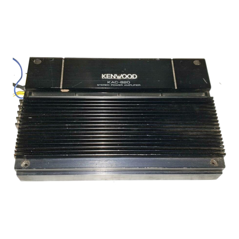
STEREO
POWER
AMPLIFIER
KAC-8020
TRIO-KENWOOD
CORPORATION
GOO/ANS>DI
©PRINTED
IN
JAPAN
B50-6148-00(E)
(T)
8712110987654321
861211109876543
INSTRUCTION
MANUAL

Take
the
time
to
read
through
this
instruction
manual.
Familiarity
with
installation
and
operation
procedures
will
help
you
obtain
the
best
performance
from
your
new
power
amplifier.
For
your
records
Record
the
serial
number
found
on
the
bottom
of
the
unit
in
the
spaces
designated
on
the
warranty
card
and
in
the
space
provided
below.
Refer
to
the
model
and
serial
numbers
whenever
you
call
upon
your
KENWOOD
dealer
for
information
or
service
on
this
pro-
duct.
Model
KAC-8020
Serial
number

Care
and
Maintenance
@
The
power
source
of
this
unit
is
exclusively
DC
12
V,
negative
ground.
If
you
wish
to
mount
the
unit
on
a
vehicle
with
DC
24
V,
please
consult
your
appointed
KENWOOD
dealer.
@
Do
not
place
the
amplifier
in
a
place
where
the
amplifier
may
be
ex-
posed
to
direct
sunlight,
heat
or
moisture.
Be
careful
that
metal
ob-
jects
and
water
do
not
enter
the
set.
@
|f
you
have
difficulty
in
installing
the
set
in
your
car,
please
contact
your
KENWOOD
dealer.
Cleaning
Clean
with
a
dry
silicone
cloth
or
a
soft
cloth.
The
use
of
thinner,
alcohol
or
other
solvents
may
damage
the
surface
finish.

Installation
*
When
installing
to
the
car,
install
the
unit
securely
for
safety
driving.
Tapping
screws
(@5
x
25
mm)
@
Use
screws
supplied
as
accessories
when
installing
the
unit.

Since
the
power
amplifier
has
no
parts
which
require
operation,
it
can
be
installed
at
a
position
away
from
the
driver's
seat
without
any
hinderances.
But
due
to
its
considerable
weight,
it
needs
to
be
installed
securely.
Use
the
extension
cables
CA-18F
(1
m),
CA-28F
(2
m),
and
CA-
48F
(4
m)
(optional)
when
the
connected
models
are
to
be
install-
ed
away
from
the
power
amplifier.
As
generally
accepted
positions
for
its
installation,
places
such
as
under
the
front
seat
or
inside
the
trunk,
etc.
can
be
considered.
Install
the
unit
in
a
well-ventilated
place
and
do
not
place
any
(heavy)
object
on
it.

Connection
Extension
cable
(supplied)
Cassette
receiver
or
cassette
tuner
Fuse
(20
A)
KAC-8020
¢
Prepare
the
speaker
cables
——
(®gray/red,
Ogray)
Left
speaker
(®gray/blue,
Qgray)
Ground
(black)
©
Grounded
to
the
metal
body
of
the
car
Connect
the
ground
lead
to
the
metal
part
which
is
connected
to
the
(—)
terminal
of
the
battery.

¢
Make
sure
the
main
fuse
of
the
car
is
connected
between
the
power
source
line
(yellow)
and
the
battery.
If
the
main
fuse
cannot
be
located,
connect
a
new
30
A
fuse.
Engine
room
————
Interior
Power
cord
extension
cord
a
UR
re
(yellow)
®
Do
not
allow
the
cord
to
directly
contact
the
edge
of
the
iron
plate
by
using
grommets
(supplied).
@
If
you
hear
a
noise
when
starting
the
engine,
con-
nect
the
line
noise
filter
CN-300
(optional)
to
the
power
source
(yellow)
of
this
unit.
Power
cord
extension
Power
supply
(yellow)
cord
(yellow)
ee
——>
cummed,

SENSITIVITY
O.5V
(LOW)
systems.
MW
2V
0O.1V
(NORMAL)
set
this
to
0.5
V
(LOW).
Precautions
Since
the
electrical
consumption
of
this
unit
is
large,
obtaining
power
source
from
wir-
Connection
SUBWOOFER
50Hz
(ie
100Hz
OFF
J
e
Subwoofer
selector
This
selector
is
for
selecting
speaker
out-
put
mode,
normal
or
subwoofer.
When
the
subwoofer
selector
is
set
to
50
Hz
or
100
Hz,
the
output
level
is
in-
creased
by
6
dB.
Adjust
the
ouput
level
with
the
sensitivity
control.
OFF:
The
normal
signal
is
output
from
the
speaker
output
terminals.
50
Hz:
Super
low-frequency
signal
hav-
ing
the
cut-off
frequency
of
50
Hz,
cut-off
slope
of
18
dB/oct
is
output
from
the
speaker
out
terminals
for
connecting
the
sub-woofer.
100
Hz:
Super
low-frequency
—
signal
having
the
cut-off
frequency
100
Hz,
cut-off
slope
18
dB/oct
is
output
from
the
speaker
output
terminals
for
con-
necting
to
the
sub-woofer.
KAC-8020
{oe
©
Input
sensitivity
control
The
input
sensitivity
control
adjusts
the
input
sensitivity
within
a
range
of
0.1
V
to
2.0
V
continuously,
enabling
expansion
with
various
Normally,
set
the
input
sensitivity
control
to
0.1
V
(NORMAL)
position
for
KENWOOD
cassette
receiver
or
cassette
tuner.
When
the
output
voltage
selector
of
the
cassette
receiver
or
cassette
tuner
is
set
to
1
V,
ings
such
as
those
of
built-in
cigarette
lighters
will
overload
the
wiring
of
the
car.
Be
sure
to
connect
the
yellow
power
lead
directly
to
the
battery
as
shown
in
the
figure
before.
@
Before
starting
to
install
the
set,
make
sure
to
remove
the
negative
(—)
terminal
of
the
battery
in
order
to
prevent
shortcircuiting.
@
When
installation
and
wiring
are
completed,
connect
the
negative
(—)
terminal
of
the
battery
after
confirming
that
there
are
no
errors.
@
When
a
fuse
is
blown
out,
check
for
any
shortcircuiting
of
cords,
and
then
replace
it
with
a
fuse
having
the
specified
capacity.
@
The
maximum
output
power
of
this
unit
is
140
W+140
W.
Therefore,
the
power
handling
capacity
of
the
speakers
connected
to
this
unit
should
be
140
W
or
more.
If
a
speaker
with
a
smaller
handling
capacity
is
connected
and
driven
at
a
high
level,
the
speaker
unit
may
be
damaged.

Specifications
Specifications
subject
to
change
without
notice
Main
amp
section
Maximum:
output
power
CL
KAZ,
Ae)
ees
snrsaesareroretidavacrencerweeks
140
W+
140
W
Maximum
rated
output
power(10%
THD,
1
kHz,
4
Q)
......................
95
W+95
W
Rated
output
power(1%
THD,
20
Hz
-
30
kHz,
4).................008.
80
W+
80
W
Frequency
response
(=
3
CB)
cccdbeagsscueouwcuicabos
tesa
eas
eane
eeees
2
Hz
-
100
kHz
Minimum
distortion
(10
W,
1
kHz,
4
Q)..........
ccc
cece
cece
cent
ee
eee
ee
eeeas
0.005%
Input
sensitivity
(at
rated
Output)
Max.
..........
cece
cece
cece
eect
eee
teat
eee
eee
es
0.1
V
NA
te
ettesea
alee
deta
ace
ee
asacla
scant
2.0
V
Sidnal-to-Moise
tation
HFA}
eewespeccseene
seeiviecheramedetdvaseidnce
ee
esettve
ee
100
dB
INDUTIMPOGAN
CG
vinci.
s
seuss
yey
cha
iwig
a
Heaven
etna
aseaen
Haeeaaes
acaReae
ea
saunas
10
kQ
DarmonnG
Factor
(UK)
iscs.c05c1
cw
tanec
ear
amie
seevenores
Quine
eaaatsnxaresnsss
More
than
100
General
Operating
voltage
(GND)
<0.
fiiaayiks
i
acivae
es
Mee
ans
14.4V
(11-16
V)
CURE
RT
COR
SUD
TOM
src
cfornseaiuarcesueusuacven
tectos
cake
AGagieesaheasuPeance
tartan
ond
.19.0A
DIMEASIONS
(VV
56
FOC
Do
tg
eidecd
teacedyer
setters
cs
mcocallasbawnber
240
x
57
x
200
mm
9-7/16
x
2-1/4
x
7-7/8
in
VIGIGHE>
faci
tent
es
osha
eee
run
anak
opens
O
sadeute
neta
abiisia
nied
Caadad
lambs
baleen
ds
3.3
kg
7.3
1b
Table of contents
Other Kenwood Amplifier manuals

Kenwood
Kenwood KC-209 User manual

Kenwood
Kenwood KAC-821 User manual

Kenwood
Kenwood KAC-PS300T User manual

Kenwood
Kenwood KAC-941 User manual

Kenwood
Kenwood KAC-848 User manual

Kenwood
Kenwood A-85 User manual

Kenwood
Kenwood Basic M1D User manual

Kenwood
Kenwood KAC-745 User manual

Kenwood
Kenwood KAC-8151D User manual

Kenwood
Kenwood KAC-721 User manual

Kenwood
Kenwood KTC-1000R User manual

Kenwood
Kenwood KA-880SD User manual

Kenwood
Kenwood KA-4006 User manual

Kenwood
Kenwood KAC-6202 User manual

Kenwood
Kenwood KAC-526 User manual

Kenwood
Kenwood KM-894 User manual

Kenwood
Kenwood KAF-3030R-S User manual

Kenwood
Kenwood KAC-728S User manual

Kenwood
Kenwood L-A1 User manual

Kenwood
Kenwood KAC-921 User manual