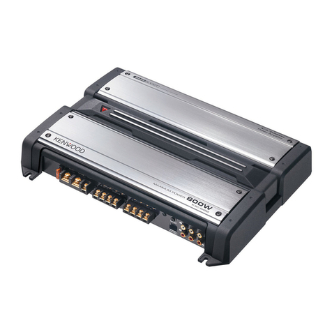
Kenwood TL-922A User manual

I
I
I
I
TALtNEALRAMP.gLlFlER,,,,,,, INSTRUCTlONMANUAL'KENWOODCORPORATlON8cg/p1R2IN1T1E1DogINgJA1pANB5o-258-4o(K2)(G)

g
3
l
q
4
y
t
3
t
I
r
AFTER uNpAcKING CAUTlO N
ItjsadvisabletosavealIoriginalpackingcartons(innerand Read Operating ManualSection 2 before proceeding to
outer) to protect your valuable Linear Amplifier from unpackandassembleyourampIifier.
1
,
,
damage should youwishtotransportitforremoteopera- wA RNING !!,
tion orship itforafter-salesservice. !,
,
ThefoIlowing explicitdefinitionsapply in thism anual.Be LETHA L VOlTAGES PRESENT.
l,suretoreadthesedefinitions.
NOTE = If disregarded,inconvenience only - no
daMage orperSOnalinjUry. j
CAUTlON = equipment damage m ay occur, but not
personalinjury.
WARNING m personal injury may occur- do not dis-
regard.
CoNTENTS
rL.g22A spEclFlcATIoNs...................3 SECTlON 6 MAINTENANCE .........,......15
Ecrlo N 1 FEAruREs ...................4 6.1 InternalCleaning
sEcr oN 2 pREpARArloN fOR USf .........5 6.2 Replacing Pow erFuses
2.1 Accessor;es 6.3 Replacing Pow erTubes
2,2 lnstallationofPowerTubes 6,4 lnpUt MatChin9CirCUit
2.3 ceneralTipson lnstallation SECTlON 7 TROU BlESHOOTIN G HlNTS .,,... 16
2.q AC pow erSource PA CKING ................................ 17
2.5 Line VoltageChange lNTERNAL PA RT LOCATlONS ..,.,,.,.,.,,,, 18
2.6 pow erCable SCHEMATIC D IAGRAM ..................., 19
2.7 Excìter
2.8 Antenna
2.9 Interconnection
2.g.1 cround;ng
IlL
F
U
ig
S
.
T
2
R
-
A
1
TI
U
O
p
N
p
S
erCaseCoverAssembly/
2.9.2 Cable Connection Disassembly ,.................... 5
sEcrloN 3 CoNrRoLs AND THElR FUNCTlONS .9 Fig.2-2 CorrectPow erTube Handling ........ 5
3.1 Frontpanel Fig.2-3 Parasìtic SuppressorCoilMounting .... 6
3.2 RearPanel Fig.2-4 lnputVoltage Term inalBoards ....... 7
sEcTIoN 4 opERArloN ........,.........11 fig.2-5 PowerCable ColorCode ............ 8 '
q.1 prechecks Fig.2-6 ExciterConnections forRLand A LC
q.2 CW Operation Controls ........................ 8
q.3 SSB operat;on Fig.2-7 Interconnection oftheTL-922A ...... 8
q,q RTTY Operation Fig.3-1 FrontView ...................... 9
-q.5 Sett;ngtheA LC ADJControI Fig.3-2 RearView ...................... 1O
q.6 Ad;ustingtheRfOutputMeter Fig.5-1 LinearPowerAmplifierCircuit ....... 13
q.7 High-Voltage Transform erProtection Fig.5-2 TransformerPriMarY Current Flow ..... 14
.8 Carrying YourTL-922A Fi9.5m3 Fan MOtOrDelaY StOp CirCUit ........ 14
sEcrloN 5 c Rculr 0EsCR prlo N ...........13 Fig.5-4 M eterDrive Circuit................ 14
5.1 LinearpowerAmplifjer Fi9.7-1 PaCkín9 fOrShipment .............. 17
5.2 PowerSupply
rAF
B
i9
L.
Es
7-2,3TOp,BOttOm View S...,,.,......... 18
5.3 FanMotorDeIayStop Circuit
5.Q MeterDrive Circuit 1.frOntPanelCOntrOIS Set-Up .............. 1
1
1
15.
5 SparkSuppressor 2 TUne and LOad InitialSe in9S
2

JlJJJIlJJJIJJJlI.JIJlIllllI-JJllIllIlI.lllJIlJJJJI.IllJI llJJIIllllIlIJlI.IlJlJI"JJlJI.IJJJJI.lJJlJI.IJJJJI"IJJJJI"JJJJI-JJJJIIJlJJI-JJJJI.IJJlJIIllJJIIJJJJI-IJJJJI-IJlJJI"IJlJJIJllJJI"JJJJI-JJJJI- I"IJJJJI JJJlI-llJlI I.lJllI.IJJllI-IJJJJI_"
-
-
_
_
_
_
'
-
-
_
,TL-922A SpECIFICATIO S =--
_
_
_
_
-
-
_
,
lJllIllJJI.llJJI.JJllIllllIJlIlIllll IlIlI IlllIIlllIllllIIlJllI"IlJJJI- m-JJJJI-mJI.JJJJI.IlJJJI.lJJJI.IJJII JlllI lJJl- I- I- -It IlJJJIlJJlI- IlllII IllJI-IJlJJI"IlJlII lllJI- JlI"IlllJI lJlIIlIllI-tllJJIIlJJJIi
Transm it Frequency Range". 160 m through 15m Am ateur Bands
Excitation Energy Required". 80 W nom inal,120 W maximum
Mode and Duty Cycle. SSB,continuousfor30 m inutes.
_
CW and RTTY,key own continuousfor1O m inutes.
Rated Platelnput.. 2kW P.E.P.SSB,1kW CW RTTY
PlateVoltage".(athlo signal) 3.1kV SSB,2.2 kV CW RTTY
CircuitType: CIassAB2 grounded grid linearamplifier
,
3rd OrderJnterm oduIationDistortion; Below -30dB.
lnputlmpedance". 50 n ,unbalanced atbetterthan 1.5SW R
Outputlm pedance.. 50 to 75 n ,unbalanced.
Cooling". Forced Air.
lnterlock Satety Features; Prim ary high voltagecircuitcut-off.
Secondary high-voltage circuitgrounding.
Therm alProtector; Locks outtransm itrelays ifH.V.pow ertransformeroverheats.
fan MotorDelay StopTime; 140 +- 30 seconds. (atroom temperature)
ALC; Negativegoing,adjustablethreshoId -8V C maximum output(typical).
powerTubesUsed. Eimac3-500Z,tw o pieces
Q m iconductors: ' i
odes,18 pieces
lenerdiode,1 piece
powerRequ;rements.. 120V,28A;240V,1qA;50/60H ;formaximum SSBinput.
Cablegsuppl;ed.. Signalcable (coaxial)withUHF-type connector,1.5m.
Controlcable,1.5m .
Dimensions; 390mm x19Omm X407mm (15-3/8X7-1/2X16'')
Weight.. Net3tkg (68 Ibs.)
Shipping38 kg (83 Ibs.)
Theabovespecificationsare subjecttochangewithoutnoticeduetotechnicalim-
provement.

o
r
m
ugg
1
(
f
7
)
lIllllllIll.llllll.llllIlillIlllIlIll.llllll.llIlllllIlIl.llIlll.lIllIl.llllIllllIllllllIl.lIllll.llllIIllIllllIlllIlHHllllIll.llllllIlIlJl.lIlllI.lHllllHHIIJllIIlIlIlIlHHIlIlllIlIlllIIIlIllllllllllllIllmIllllHllllllllIlIllllIllllllIllllllIl
_
,
=
-
_
_
-
_
_
-
.
.
sECTIO N 1. FEATU RES =-
_
_
_
_
-
-
_
,
íilJllt,llJlll.lJJlllllllJlllJIllllllll.l llllIllImJl.l ll.I -IlIlIliHIJl.lIJJJllIlIll-l l-l -l IlllIlIIIlIlIllllllllllll.lIlllllIlIll.llllIl.llIlll.lllIlllIlIJIlIllllllIlIlllllllllllllillIlllllIll-I lllIllllHHIllllll-llIJJl.llIllli
1. The T L-922A is a ClassAB2,grounded grid linear linearity,and the CW Modeforlow powerconsum p-
am plifier developed by Trio-Kenwood through ad- tion and heatgeneration during extended periodsof
vanced high-power technology using tw o high-per- operation. '
,
,
formance Eim ac 3-500l power tubes. lt covers all :
bands 160 m through 15 m forSSB,CW and RTTY 8. linearAmpIification ControlSw itch '
modesofoperation. ThisswitchiscapableofsettingyourT L-922A inthe
straight-through state irrespective of the standby
2. Unprecedented Reliabjli control on the exciter. !
,
'
'
!
The T L-922A isdesigned to providestable,high RF
tputpowerrorextended per;odsorcont;nuoususe. 9. VariabIe Threshold Level(ALC Detector) ,
,
E
U
n
e
g
c
;neered w;thTr;o_Kenwood,sadvanced c;rcu;tand TheA LC circuitwiIlaccomm odateexciterSof80w
h
e
an;caItechnoIogy,the TL_922A empIoystwo to 120 w (nominal)by varying the ALC threShold
d3_5oozpowertubestothe;rruIIadvantage. I
p
evel.This effectively prevents overdriving the final
owertubes, ;m ;t;ng theAm pI;f:erto :tsl:nearrange
,
3. low ntermod,lat;onD ;stort;on andgUaranteein9lOW diStOrtiOnatMaXim UM POWef i.
,
'
'
Intermodulation distortion (lMD) is minimied
throughtheuseofnegativeR.f.feedback. 1O. TwoPanelM etert i
lnadjustingormonitoring yourTL-922A,onemeter
q. Qu;c Turn.on aIwaysindicatesthe(lp)platecurrent;while,with'the
Warm-up isnotnecessary.The3.500Z tubesarefast other,you may read (Ig)grid current,(RF)relative
!
!
,
,
heatjng. output,or(HV)highvoltage. Thisfacilitatesease of !'
operation ofyourTL-922A.
I,'
5. FullSafetySystem !!,
Toprotectyouagainstanypossible high voltageelect- 11. RigidMechanicalStructure
,
i
i
r;c shock,yourTL-922A hasadouble safety system Thedie-castsidepanelseffectiveIysupporttheweight t
.
,
comprised of interlocking switches.One interrupts of the amplifier against shocks and jarring during ,
the high voItage primary circuit w hile the second transportation.Recessed side panelhandles are pro-
,
directly grounds the secondary high voltage circuit. vided so the AmpIifiercan be easily carried.
,
'
Also provided arebleederresistorsfordischargingthe
high voltage capacitorsand ''DA NGER''warningsat 12. VernierPlateTuning 0ial
high voltage positions. Please observe allwarnings, The PLATE tune dial is equipped with a reduction :
they are for your protection. gear thatfacilitates easy tuning,particularly forthe '.
,
,
higherbands. ltalso effectively preventsaccidental í'
6. hlewly-0eveIoped fanMotor0elayStopCircuit miss-tuning during operation. Controls and panel '
,
.
,
,
,
To reduce power tube deterioration,yourT L-922A arrangement
,
designed to hum an engineering
has a newly-developed fan motor delay-stop circuit standards
,
provide superior ease of operation. !
com prised of a thermaldelay relay.The cooling fan
wiIInormally runfor1QO seconds(Typ)afterpower 13. eat,ContemporaryAppearance
is rem oved from the un;t and w iII measurably ex- M echanjcalarrangementand sophisticated design tO
.tended tube life. m atch any Trio-Kenw ood tranSCeiverOrtranSm itter.
YourTL-922A can aIso be used as a high-quality,
7. ModeSwitch forEffic;entLinearOperation generalpurpose Amateurband IinearampIifierWith j
,
MODf switching js provided to select between the any excitercapableof80W to 12OW Rf OUtpUt,
,
;
SSB Modefor the maxim um PEPoutputwith good i
,
'
.
4

,Ns,DEpAuccoAp,,pvsEEEEEwRRs'--____?--_,,',',',','.'.'.',,'',.'.'.''.',',',','.'.'.',',',','.'.'.',',',','.'.'.',',',','.'.'.',',',','.'.'.',',',','.'.'.,'.','.'.'.'S.'H'.,.E-..',",C.-'.T'.'.I?H,H'..!.H,,'N,','.'.'.','.',!,',.!.!,',!.,','.'.'.',',!,!,,..',,,R',,!.''.'.!E,',!,!,'.p'..',!,!.'A,'.'.'.'.!,!!.R!,'.'.!.!A!!''.-.T'.','.!,.'.'I'.'.'!!!..',!N.',!,!,'.'.',',','F,!.'.-.',!o.',!,!,!.''.R!,!,!,!,','.'.',',!,!,,.'.',S,,,'.'.'.E,!.!.!!,'.'.'.",,,.'."..',','.','.'.'.',',H,,'.'.'.'',',',','.'..'',',.'','.'.'.','.',''.-..',',',','.'.'.',','.','.'.-.',',','.'.'----____--_,,2.tACCfSSORIfS 4.RemovetheshieldpJate.AI.,5Takethetubesoutoftheircase(RefertoFig.1-2).InrcefkUlttyhatUnpaCkyOUrTL-922ALinearmplie,,nd'.,i,.ssuppI.,edw.,ththefoIiow.,ngaccessor.,eshandling,besuretoholdthembytheglassenvelope,I5o25g72o'nottheplatecap.JnStrUCtiOnManUa--1CODy'6CarefulIyindexthepinsofeachtubeintoitssocket.COaXialCabl0,1.5m,withUHf-tYpe'andinsertgently^ithoutexcessiveforce.COnn0ctOfSX42-11OO-OOtpieCe3.ControlcableW/8PinPlug1piece(Fqo2rr1s1_15o2o1Ts_g2os$,;es),NsERTuppERs4cmRm'o cAsEcovER4.XCont-rolcab-leW/7PinPlug1pieceLNErAo0lFNRGoNEDTGE1(Fo,Ts-12ois-13ois-18oTs-43opANELToPL,p!!!,is-qqois-'53o,Ts-'g3oTs-'93o,'H,,HvoL,A,E\TS-940'Series)X42-111O'-11 PRlMARYPROTECTlON
5. spareruse,15AFo5-1533-o5 2p;eces .. ,,,SiITCHPLUNGER
?
6. ExtensjonfootJ02-OOQ9.14 2pieces I'
''
3
A
mp
m
p,
S
NE
,
LF-
7. Scr$ws,4 x 12m m long N30-QO12-46 2 pieces 3,m F,A,
l
HEA ^\\.. , ,scREws
8. Platgcap F02-0407-04 2 pieces sELF-TAppN, \ ' \'\\ g l - '
g. paras;t;csuppr$ssor ;I,,;ghih,nd 1p;ece scREw (4pcs) '
,
' -', t l
L3g-o4o1-o5 H,,H,oLl
TA,, !
.
,
,
1O. Parasiticsuppressorcoil,lefthand 1piece sEcoNoARy ' !!i
L3g-o43
o2-o
65
I N3o 3oo6 q6 q
pROTECTlON ' -' '
.
eces sw,TcH I 'ì ''
!
1
S
/
H
,
l
E
t
L
O
..!
,
PLUN,ER I \1
1
1
2
3
1'
.
S
s
PC
l
p
a
!
r
i
0
,
n
w
w
'
as
X
her
M
N?
150
-1
?0
9
30-46
- -
Q P
p
!
i'eces j ,,,. '
,gwashe,N16. 3o-q6 qp;e,es J 1 ? /,,!\?,, ',','.!
0b' ' P !
,
!
!
,
'
'
1
2 2
'
INsTA LLAT oN o Fpow ER TuBEs -
x\x\ \
'
!
! ni
v,
o
'
p,oig,t thg power iubes ,, your TL g22A ag,,,si \ /?<?XXm ? '
i
i
'
'
-
'
.b,ai,.o, ,,d h , d .
- ì ^? '' TT /!pí
.
Oie,Umni0.,,,.et,''nSPO,th'YW'r'Pa'k'd l --/'''t'' 1//
fO'inSe'tiOn,fOllOW th' \ "' / i
/
/ '
//!/S
p
e
ro
P
c
a
e
ra
d
t
u
0l
r
Y
esfrO
below. Prepare the following mounting \"\? /
/i
//
hardware and iools. ,'
/ //-
Mou,t,,g H,,dw,,e UPPER
co
Cv
AE
SR
E ) i/ / Figur02-1
p
p
owe,tube,3.5ooz 2 p;eces ,NSERT UPP0r C8s0 Cov0r
.
,eces
._) m Assgmbly/Disgss0mbly.
pa
l'
r
t
,
'
s;
C
t
a
;,
Psuppresso,co; ,;ghth,,d
2 P
Sw,TcH USE #2 Phillips
,,d Iefih,,d
'
1p;ecee,,h PLUNGER Scr$w driv$r.
re^,3x6mm long 4pieces
Ptainwasher 4 pieces
,
.
Spring^asher Q pieces !
Tools
Phillipsscrewdriver 1piece i \ \S
mallstandard screwdriver lpiece
,
h?
,
NOTE. A partstray to preventlossofm etric hardware is ,
hetprul. - ;
,
,
'
,
'
,
,
i
.
,1.i
,
,
WARNlNG.Betoreproceeding,makesurethat. )!i'!'ii,iiI!!,rhgpow0rc$bl0;sNoTplugg0d;nth0w8llout- \ 11
i
!
,
'
,
l$t.Th0METERswitchis$tth0HVposition ',
8nd th0 m ultím $t$r r0$ds OV.
Proceed asfollows. (Referto Fig.2-1) h???
?
'
-
_
.-
-
1. Remove the four4 m m Phillips scre^sholding the
_
'
-
'-
upper case cover.
'
2. Removetheuppercasecover. .
ph.iI.
Figur0 2-2 - 0 rre Po
R'MOV' !h' tOUr 3 ? M S'l!-"PP'n9 ' !P'SCr'^S ru Handl;n
and fOU,fl,theadSelf-t,ppin9 PhillipSSCrewShOldin9
theinsideshield onthepowertubeenclosure.

N 3cENERALT
Ips o N JNsTALLATJo N
?
1
t
l
I
CAUTIO N TubelnstallationCheckout
part;cular care should be taken not to strike and 1. To avoid daM age neCeSSitating tUbe reptaCeMent,
break the glasstubesduringinstallation.Tube break- pleaSeCheCk;
ageduetonegligenceisnotw arrant a. Powertubes are freefrOM SCratCheSorOthef
physicaldefects
.
(
p
R
re
efertoFig.2-3)TeMpOrarilyfiXeaChparaSitiCSUp- b i b r I, .' d. , .
rco;,onthe piate capw ;ththe,etter,,R,,or,,L,, U ''ar' U Y '?S'r'' 'n'O ' ''r'O'k'''
.
,
S
,
S
g
Oup Att,,st,, e donott,g,te,,,eq , , s,rew C PlateCaPSCreW St'l9htenedSeCUfeIYt
''
, ., b d Scre,satboth endsof theparasiticsuppressor
a
a
n
C
d Sprin9 W aSher,bUtSnU9 theM SO t e COl M aY e '
., ,.
adjusted. wCO,S
,are '9htened
dS
.
eCUreIY'
h
8. mount,,ep,a,ecap w;th paras;t;csuppressorcoiton ' "' 'r','Cr'w', f'V'r''n 'nY O' 'rU'n''''- i
e
d
ach ,ube observ;ng the r;ghthand and ,erthand co:, S'rY Ma''f'''iSnO'''!'i?Sid''h'U?i'
2 Referto Fig 2-1 Theinsideshield plate includesthe
!
,
esignationslfthescrewhoIeSdonOtali9n,Shape ' '' ,' highvoltagesecondaryprotectionswitchplunger(a,theCoiIbySli9htbe'din9OreXtendiD9byhandfOr bakelitebar)PositiontheplatesothatthepIungerwipreciseinstallation,keepingtheCoilbeIOWtheteVel 'securelyengagethespringplateforungroundingthel
of the pIate cap. , h.
cAuTloN..pait;cularcare shouId beexerc:sed Jn not
3 P'!',,
!9h VOl'a9'
., . , d. , .
apply;ngexcess;veforceto thetubes. l?S"
(
'h' UPP'r C'
,
S' C
1
0V'',
W.!'!'ia!n9'9'i,!.n- :
g. careru,iyi;ghien,hescrewsa,eachendortheco:, i';'.'d'PPr;XiM,a,";.,M~,n'O'.'rO?'P'Ç',.'P
whileholdingtheplatecap by hand. .'S
,
COV
,
eF aS
p
e.
t.
'9
,,
VO age PrIM
,,
aFY ,
PrO eC 'V
.,
e
, :
1o. T;gh,en ihep,atecap scre, us;ngihe smat,standard SW!"
,
P
,
Un9'
.f OS
.
'
,!O
,
" ' 'OV "'O 'P Un9'rW'
!
screwdriver. en9a9e eM ICrOSW 'C '
,
,
11, CheCk to assure correct installation by reference to
F:g.3-3. 2-
Installin a dry, well-ventilated area,shaded from direct
Sun light. Your TL-922A m ust h8v$ 8 m inim um
clearanc$ oF15 cm to th$ r$8rto 8IIow hot8ir8t50 to
70^C to exh$ust. ,
,
; Choose an operating position capable ofsafely supporting
1;
OT
Be
EfOre 'l?Stallat'lO?,CheCk eaCh PafaS'lt'ICSUPPfeSSOrCO'llfOr
,,e ,e.,ght or the TL.g22A (31 kg),pIus a,,,he o,he,
good alignmenttopreventthe application ofexcessiveforce
tothetubes. station eaUipm ent.
2; Letters''R''and ''L''onthecoiIsshouIdfaceup. . . T, d ,
3.Temporar;Iy ;nstaIIeachco;Ion the;rpIatecapsbeforet;naI LeVelyOUrTL922A InOperatlOn. eheate eeCtrOdeSin i
,
.
tightening. Use# Philipsscrewdriver. each powertube willbe distorted by gravity resultingin
shortened service life,ifslanted beyond 100.
'
'
!
.
,
,
aspRINc wAsHER 2.q Ac pOW ER SOU RCE
'
'
,
F,ATwAsHER USe an AC PoWer line haVi?9 SUffiCientCUfrent CaPaCitY
, ,
or the performance of your TL-922A will be adversely
IiI11l!, ! ii,'I'IIllll arrec,ed by ;nadequateI;neregu,at;on. In,hewors,Case,
do no, devía,e ,ore than +_1OO/o froM the rated input
3
,,! ' voltageforwhichyourAmplifierhasbeenset.
\ ,, \\
?0 -h ? 2.5 LINE voLTAc E cHANGE .
;
.
'
,
,
/ '
,
i
'
'
0 g
'
' '
'
.
WA RNlNG
)r'!-'--
i
'''
D
FI
R
S
o
CO
M
r
N
H
E
E
CT
TL
T
g
H
2
E
2A
AC
BE
I
F
No
PU
RT
E p
PR
Oo
Wc
E
E
R
EC
DA
,N
B
G
lE !
!
,
Xs
xx ''?? iJ xx\ '''?? - ' !
,
'
m?
?/ hmm? ?? TheinpUtVoltageCanbeChan9edtOeither240VOr120VaS
II -_.__. requ;red,bychang;ngt,epowertransrormer:nput,:nks ,.,,
ocated in the ducton the rearpanel. '
,
.
,
NOTE; TheTL.922A w asfactorysetinthe 240V position. !
,
,
,
figur$ 2-3 - P$r8sitic Suppr$ssor CoilM ountin9
6 3!''''''
,

2.1
e
ExcITER qToomTGoARR2EoqoLuA/N1y20ov+L1D,oNcoEvTo,hangelinkpositions,removetheaccess,overbytheTrio-Kenwood'stransceiversSeriesTS-930,TS-940,twoblacksnapfasteners.loosenthescrewsholdingtheTS-830,TS-820,TS-530,TS-520,TS-430,TS-440S,shortin;bars,afewturnsonly.(0onotloosenexcessivelyTS-180,TS-130,TS-t20andTS-900andtransmittersastheycoulddropintotheAmplifier.)DraweachshortingSeriesTX/T-599areallsuitabteexcitersandwillmatchbarupwardforremoval.ReplacetheshortingbarsforthetheTL-922Aindesignaswellasappearance.Operatin9VOlta9edeSiredaSilIUStratedinFi9.2-4.Ti9htenorE..whentheTsqqos;sused,themod;r;c,t;on;sne_firmly.Also,besuretotightenthescrewsfromwhichthecess,.ShOin9barSwerereMOVed. Rerertorsqqos;nstruct;onm,nu,I.hlOTE..FusesneednotbechangedincúrrentratingwhentheinPutvolta9eiSchan9ed.2.gANTENNACAUTlOExCeSSfOrCeMaYbreaktheterminalStriP.yourTL_g22A,eq,;,esa,a,,,,,,h,v;,ga5oto75nimpedanceandprovidingitis.2T.h6POWERCAlE (1)Ratedfor2kWp.E.p.inputpower,edw,thyourTL_g22Ah,snopIug(2)and,exhibitalowanding-waveratio(SWR),tsDOeW,'df.'acbol',,SUe,PtPlapIugm,t;,gw;ththewaIo,tIet.DesiredSWRis1.5to1.orIess.AhigherSWR,2OfaTthebueandbrownIeadsa,epower,thegreenIeadground3tOl,MaYCauSediftiCUltrnatChin9WithYOUrTL-as,IIust,a,ed;,F,gu,e2_5. 922A.ExCeSSiveSWRCouldmeltthecoaxialcable
and antenna. To protect your TL-922A against
adverseSW R effects,usean antennatuner. Notethat
feeder radiation due to m ism atching willcause TV l,
An HF AmateUrband SSB OrCW tranSm itterOrtranSCeiVer BCI
,
orsj, ;lar RfI.
having anRFoutputim pedanceof5O© andoutputpowerof
80W to 120W is sutficientto drive the TL-922A. Exciter
output exceeding 120W w illcause overdrive,resulting in
sho ened pow ertube lite anddistorted output.To lim itthe BLACK
pow erlevelabove 120W ,use anexciterhaving an external
ALc ;nputterm ;naI. W HlTE
i.i'.''?.'!.
.
',íi,
'
l
,
.
'
,
jí,'i.''.
i
GREENCAuTION.BESURETOTIGHTENALLSP''''hO"'n9b'''LoosENEDscREws.F;g,,g2.5-powgrcgblgcoIo,codga'eteCU'ed'tterminaIS3'ndQ.use#ph;I;psscrewdr;ver.a.240Vsettingg'!oo'o?i'2sq5678ExC,TERTL-g22Ao;!.!,-!TRANsM,T!iRLCONTROL!ib.11ovsettingR,,,,,E,,,,!!!!!,,,g''ogTCOIRACULCT!!ALCCONTROL!!!ALCiO-20l2St5678,, ,Figurg2-6Figurg2-4-InputVolt8ggT$rminglBo8rdsfcit0rConionIforRLaALC0mrolI.

I
I
I
I
r
2.g INTERcoNNEcTIoN (The ALC output atno signalinDutis
2.g.1GRou ING normallypositivewhen notconnectedto
conneci ihe GN0 posts of the TL-922A and theexciter.)
exciter to prevent posSibIe eleCtriC ShOCk and TheRL,
orst,ndby control,;n theexc;termustbe .
.
,
'
RFl. The Wire USed ShOUld be aS thiCk and sw;tched tog,ou,d ;,t,ansm;tmode,
as;II,strated
shortaspossibleand runto agood earth9roUnd. ;n F;gure 2_6.
2.9.2 CABLE CONNECTlON NorE,
.
use Rc_g/u, Rc.11/u or heav;er as
'
!
,
.
Interconnect yourTL-922A and exciterw ith the ,
,te,,,c,bIe
supplied cables as illustrated in Figure 2-7. '
NOTE; If an SW R meteris COnneCted betWeen !i
NorE. Ir you use an exc:ter ot anotherbrand, ihe iL.g22A a,diheexc;ier,iotaIco- t
replace the supplied conneCtOr With One ax;alcab e engih mustnotexceed 1.7 m.
appropriatetoyourexciter.Theeciter j
used m ustacceptthe negative-goingA LC t
voltagefrom theTL-922A. '
,
!
i
,
'''
!
,
,
,
8
'
!
'
t

T ?,JJJ,.,J,JJ,.,JJJJ,.,JJJJ,.tJJJJ,.,JJJJ,.,JJJJ,.,JJJJ,.,JJJJ,.JJJJ,.JJJJ,.,JJJJ,.tJJJJ,.,JJJJ,.JJJJ,.JJJJ,.JJJJ,JJJJ,JJJJ,tJJJJ,.lJJJJ,IlJJJJ,lllll,lJlll,llllI,.llIll,lIlIJ,lllll,lJlll,lJllI,lllll,llJllIIlllll,'llIll,'lJlll,'llllll'lllll,'lllIl,'lllJl,'lllll!----.sEcTlo3coTRoLsADTHElRFucTlOhlS'-_--_-'-''i,JJJJ,.,JJJJ,.,JJJJ,.,JJJJ,.,JJJJ,.,JJJJ,.,JJJJ,.,JJJJ,.,JJJJ,.,JJJJ,.JJJJ,.,JJJJ,.,IJJJJ,.,JJJJ,.,JJJJ,.,JJJJ,.,JJJJ,.,JJJJ,JJJJ,,JJJJ,lJJJJ,lJJJJ,tJJJJ,.lJJJJ,IlllllI.lllll,t,tllIll,tlIllIlllll,llJllIlllll,lllll,lllll,tllllll'lllJl,'llIlJl'llJll,'lllJl,'llJlJ,'q11215316
7
8T
g 1
T
1 1
T
O
Figurg 3-1 Front P8n$IVi$w
3.1 fRONT PAN EL
1. IPM eter 9. M ETER Switch
The lp meterreadstheplatecurrentflowingthrough SelectsIg(gridcurrent).RF(relativepoweroutput),or
thepowertubes. HV (plate voltage).
2. O A lR lndicator 1O. BAhl0 Selector
The ON AlR indicator lightsup in the on-the-air, Set for the Amateur band in w hich operation is
ortransmit MODE. desired.
3. PLATE TuningControl 11. LIhlEAR Switch
Thiscontrolperm itsyou to tune theplatecirCUitto ln the STBY position
,
the exciter runs straight
thedeSiredtranSM itfre nm ,and iSeaUipped w ith a through.ln the O pERATE position, the Am plifier
redUctiongearforeaSy tUnin9. autoM atically kevsw iththeexciter
.
4. M ultimeter
The Multimetercan read the lg (grid current),RF
(relative power output), or HV (plate voltage)as
.
selected bv the M ETER switch.
5. STBY lndicator
W ith the unit turned on,shows unkeyed or receive
state.
6. lOA0 Control
lmpedancem atchesthepinetworktotheantenna.
7. POW ER Switch
A double pole sw itch com pletely disconnectstheAC
inputtrom thetransformers.
8. MO 0E Switch
t for SSB orCW.For RTTY operation,setthe
switchtotheCW position.
9

IttJosmxnTuqfII
l
n
t
t
I
I
1 2 3 4
$
'
'
''''
'
'
''
'
'
'
'
'
'
'
'
'
'
Ti'.r''''''T'''''d'^T,!g'''gp''''.T'''',,..,,,,,..,,,,,,,r.,,',''''', '!,,
5 6 7 1o 8 9 11 12
Figur$ 3-2 R$8rP8n$lVi$w
3.2 REAR PAN EL
'
.
,
1. Cooling fan 8. RF lNPUT Connector
TheCoolingFancoolsthepoWertubesandeffectively ThisUHf-typeconnectorinputstheRFsignalfed
keeps the insíde tem perature from increasing. Be from theexciter
.Usethesupplied ,abIe.
carefulofhotair(500to700C}attheexhaustPort. g.RFourpuT Co,,e,tor ..,
'
2. LineVoltageChangeTerm inals This U Hf-type connector feedsthe RF output to
These term inals are tocated behind the rear cover, the antenna.
,
'
WhiCh iS reMOVed bY PUllin9 the tWO SnaP faStenefS. 1o.cN post
,
,
.
,
'
FOfinPUtVOlta9eChan9e,PleaSerefertOSeCtiOn 2.5 use th;spostto ground the TL_g22A to yourexc;ter '
3. SerialNo.Plate and station ground.
'
!
,
ThiSPlate iSStaM Ped W ith the SefialNUM berOfYOUr 11
.
FusEHoIde,s(2} '''';
TL-922A, E,,hco,t,;nsa 15A ruse.
Ire;the,o,both r,sesa,e !.,
,
,
4. RF M ETER Control blow n,determ inethecause beforerepJacement. '''
Thiscontrolisused to calibratetheRf outDutread- 12 pow ER cabIe ''!
.
ing.Forcatibration,seeSection 4.6. '
Ac pow er,.ssuppl,.ed to the ampI,.F,.erby, three_w .,re '.
,
5. ALC A DJCOntrOl cabIe.
(See section2.6) '''
,
,
Thiscontrolisused to adjusttheALC voltage.for ,.'"
adjustment,seeSection4.5. '',,
,
,
6. ALC OUT Jack '
.
ThisjackfeedstheALCvoltageout.
,
'
7. RL CONT Jack
,
'
Thisjack inputsthe transmit-receiverelay switching .
,
''
'
'
,
ground from the exciter.
,
i
'
c
,
..
,
,
.
C
,
.
,
,
'
l
'
'
.
'
1O ''''
,
,,
.
t ,
'
j''


Other manuals for TL-922A
1
Table of contents
Other Kenwood Amplifier manuals

Kenwood
Kenwood KAC-X401M User manual

Kenwood
Kenwood KM-992 User manual

Kenwood
Kenwood KAC-745 User manual

Kenwood
Kenwood KM-X1000 User manual

Kenwood
Kenwood KA-7100 User manual

Kenwood
Kenwood KM-Z1 Guide

Kenwood
Kenwood KAC-8020 User manual

Kenwood
Kenwood XR1000-1 User manual

Kenwood
Kenwood R-SE9 User manual

Kenwood
Kenwood KAC-823 User manual

Kenwood
Kenwood KM-Z1 Guide

Kenwood
Kenwood R-A100 User manual

Kenwood
Kenwood KAC-849 User manual

Kenwood
Kenwood 500 User manual

Kenwood
Kenwood KAC-7202 User manual

Kenwood
Kenwood L-07C User manual

Kenwood
Kenwood BASIC M1D User manual

Kenwood
Kenwood KAC-PS100 User manual

Kenwood
Kenwood KAC-M3004 User manual

Kenwood
Kenwood X801-5 User manual