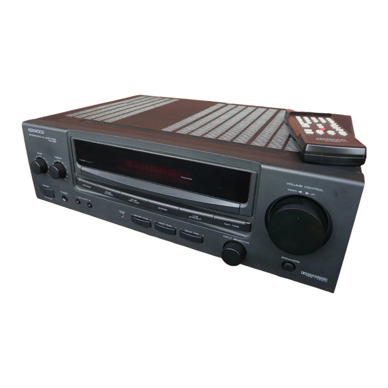
Kenwood RA-54 User manual

STEREO
REVERBERATION
AMPLIFIER
RA-54
INSTRUCTION
MANUAL
KENWOOD
For
your
records
Record
the
serial
number,
found
on
the
back
of
the
unit,
in
the
spaces
designated
on
the
warranty
card,
and
in
the
space
provided
below.
Refer
to
the
model
and
serial
numbers
whenever
you
call
upon
your
dealer
for
infor-
mation
or
service
on
this
product.
Model
Serial
number
Unpacking
Unpack
the
unit
carefully
and
make
sure
that
all
accessories
and
cables
are
put
aside
so
they
will
not
be
lost.
Examine
the
unit
for
any
possibility
of
shipping
damage.
If
your
unit
is
damaged
or
fails
to
operate,
notify
your
dealer
immediately.
If
your
unit
was
shipped
to
you
directly,
notify
the
shipping
company
without
delay.
Only
the
consignee
(the
person
or
company
receiving
the
unit)
can
file
a
claim
against
the
carrier
for
shipping
damage.
We
recommend
that
you
retain
the
original
carton
and
packing
materials
for
use
should
you
transport
or
ship
the
unit
in
the
future.
Important!
U.S.A.,
Canada,
Australia,
U.K.
and
Europe
These
units
are
not
equipped
with
an
AC
voltage
selector
switch
and
the
discussion
of
such
a
switch
that
follows
should
be
disregarded.
All
other
countries
Units
shipped
to
countries
other
than
U.S.A.,
Canada,
Australia,
U.K.
and
Europe
are
equipped
with
an
AC
voltage
selector
switch
on
the
rear
panel.
Refer
to
the
following
paragraph
for
the
proper
setting
of
this
switch.
AC
voltage
selection
This
unit
operates
on
110-120
volts
or
220-240
volts
AC.The
AC
voltage
selector
switch
on
the
rear
panel
is
set
to
the
voltage
that
prevails
in
the
area
to
which
the
unit
is
shipped.
Before
connecting
the
power
cord
to
your
AC
outlet,
make
sure
that
the
setting
position
of
this
switch
matches
your
line
voltage.
If
not,
it
must
be
set
to
your
voltage
in
accordance
with
the
following
direction.
Note:
Our
waranty
does
not
cover
damage
caused
by
excessive
line
voltage
due
to
improper
setting
of
the
AC
voltage
selector
switch.
AC
110-120V~
«pm
AC
220-240V~
AC
110-120V~
4m
AC
220-240V~,
Switch
lever
ois
@
—®
)
This
shows
switch
This
shows
switch
lever
is
locked
in
lever
is
locked
in
110-120V~
220-240V~
position.
position.
Move
switch
lever
to
match
your
line
voltage
with
a
small
screwdriver
or
other
pointed
tool.
AC
voltage
selector
switch
For
United
Kingdom
The
mains
plug
must
be
removed
from
the
wail
socket
prior
to
any
internal
examination.
Important
The
wires
in
this
mains
lead
are
coloured
in
accordance
with
the
following
code:
The
wires
in
this
mains
lead
must
be
connected
to
the
terminals
in
the
plug
as
follows:
Wire
colour
Plug
terminal
marking
N
or
Black
L
or
Red
Brown
to
Live
Blue
to
Neutral
Plug
Notes:
@
——____________________
1)
If
a
13-amp
plug
is
used,
this
must
be
fitted
with
a
5-amp
fuse.
2)
If
a
3-pin
plug
with
earthing
contact
is
used,
no
wire
must
be
connected
to
the
E
terminal.
WARNING:
TO
PREVENT
FIRE
OR
ELECTRIC
SHOCK
DO
NOT
EXPOSE
THIS
APPLIANCE
TO
RAIN
OR
MOISTURE.
PRINTED
IN
JAPAN
B50-5689-00
(K,M,X,E)
(T)
E
6789101112/85
123456789101
112/86

Controls
and
indicators
REVERBERATION
AMPLIFIER
RA-54
ATTENJATOR
REVERB!
@
POWER
switch
Depress
the
power
switch
and
the
lamp
at
the
center
of
the
reverberation
indicator
will
light,
indicating
that
the
power
is
ON.
To
turn
off
the
power,
depress
the
switch
again.
@
MIC
jack
Used
to
connect
microphone.
©
MIXING
control
To
raise
volume
level
of
microphones,
turn
this
control
clockwise.
To.
raise
volume
level
of
sources,
turn
this
control
counterclockwise.
When
the
microphone
is
not
used,
set
this
control
to
SOURCE.
©
TAPE
monitor
switch
ON:
To
playback
a
tape
deck
connected
to
the
amplifier
or
to
monitor
the
sound
being
recorded.
OFF:
To
listen
to
other
program
sources
(FM/AM,
turntable,
microphone,
etc.)
connected
to
the
amplifier.
@®
FUNCTION
switch
SOURCE/MIC:
To
add
reverberation
effect
on
to
both
sources
and
microphone
sound.
MIC:
To
add
reverberation
effect
only
on
to
micro-
phone
sound.
Safety
precautions
CAUTION
RISK
OF
ELECTRIC
SHOCK
DO
NOT
OPEN
@
EFFECT
switch
To
obtain
a
normal
reverberation
effect,
set
this
switch
to
the
1
position
(2).
To
obtain
a
dual
effect,
set
the
switch
to
the
2
position
(.).
@
Reverberation
indicator
This
is
used
to
visually
check
the
reverberation
effect.
The
lights
of
the
indicator
lamps
will
spread
to
left
and
right
according
to
the
strength
of
reverberation.
@
REVERB
TIME
control
Adjusts
the
reverberation
time.
With
the
effect
switch
in
the
1
position,
the
reverberation
time
is
adjustable
from
O
to
2.5
sec.,
and
in
the
2
position,
from
30
to
80
msec.
@
DEPTH
control
Adjusts
the
amount
of
reverberation.
Turning
the
con-
trol
clockwise
will
emphasize
the
reverberation.
@
REVERBERATION
switch
This
switch
turns
the
reverberation
unit
ON
and
OFF.
@®
ATTENUATOR
switch
This
switch
is
used
to
reduce
the
input
level
to
1/2,
eliminating
any
possibility
of
distortion
due
to
high
input
signals.
CAUTION:
TO
REDUCE
THE
RISK
OF
ELECTRIC
SHOCK,
DO
NOT
REMOVE
COVER
(OR
BACK).
NO
USER-SERVICEABLE
PARTS
INSIDE.
REFER
SERVIC-
ING
TO
QUALIFIED
SERVICE
PERSONNEL.
The
lightning
flash
with
arrowhead
symbol,
within
an
equilateral
triangle,
is
intended
to
alert
the
user
to
the
presence
of
uninsulated
‘dangerous
voltage’
within
the
product's
enclosure;
that
may
be
of
sufficient
magnitude
to
con-
stitute
a
risk
of
electric
shock
to
persons.
The
exclamation
point
within
an
equilateral
triangle
is
intended
to
alert
the
user
to
the
presence
of
important
operating
and
maintenance
(servicing)
in-
structions
in
the
literature
accompanying
the
appliance.
2
RA-54
(K)

System
connections/Operating
instructions
Turntable
Speaker
system
Pre-main
amplifier
TAPE
REC
PLAY
©@Ox2
Not
for
U.K.,
Australia
and
Europe
Tape
deck
SB
OORT
SBoonno
coo
Connections
and
precautions
1.
Each
connecting
cord
must
be
connected
securely
to
the
corresponding
terminals
(R
to
R
and
L
to
L).
Poor
connection
can
result
in
production
of
noise.
.
Before
connecting
or
disconnecting
any
cord,
be
Sure
to
turn
off
the
POWER
switches
of
the
RA-54
and
pre-main
amplifier.
.
Do
not
bind
the
input/output
cords
together
with
the
power
cord
and
speaker
cord.
Do
not
extend
the
in-
put/output
cords
unnecessarily
to
avoid
the
possibility
of
producing
noise
or
deterioration
of
tonal
quality.
)
Safety
precaution
for
AC
plug
(For
Canada)
CAUTION:
TO
PREVENT
ELECTRIC
SHOCK
DO
NOT
USE
THIS
(POLARIZED)
PLUG
WITH
AN
EXTENSION
CORD,
RECEPTACLE
OR
OTHER
OUTLET UNLESS
THE
BLADES
CAN
BE
FULLY
INSERTED
TO
PREVENT
BLADE
EXPOSURE.
-
UNSWITCHED
100W
MAX.
(+r)
To
AC
outlet
AC
outlet
(UNSWITCHED)
This
outiet
provides
power
when
the
unit
is
plugged
into
an
active
AC
wail
outlet,
regardless
of
the
setting
of
the
POWER
switch.
Its
maximum
capacity
is
100
watts.
Operating
procedure
1.
2.
3.
Depress
the
POWER
switch
to
turn
on
the
power.
Set
the
pre-main
amplifier
tape
monitor
switch
to
TAPE
or
ON.
For
playback
of
tape,
set
the
TAPE
monitor
switch
to
ON.
For
listening
to
other
program’sources,
set
the
switch
to
OFF.
Set
the
REVERBERATION
switch
to
ON.
.
Set
the
EFFECT
switch
to
the
desired
position.
.
Adjust
the
REVERB
TIME
control
and
DEPTH
contro!
as
required.
.
When
the
microphone
is
used,
set
the
FUNCTION
switch
to
SOURCE/MIC,
to
add
the
reverberation
ef-
fect
on
to
both
sources
and
to
microphone
sound.
Adjust
the
relative
sound
level
between
source
and
microphone
with
the
MIXING
control.
To
add
the
reverberation
effect
only
on
to
microphone
sound,
set
this
switch
to
MIC.
.
To
eliminate
the
reverberation
effect,
release
the
REVERBERATION
switch.
RA-64
(K)
3

Connection
diagram
Connection
diagram
for
amplifier
with
two
pairs
of
tape
jacks
2nd
cassette
deck
Main
cassette
deck
Reverberation
amp.
TAPE
EC
PLAY
LINE
TAPE
REC
PLAY
© @
Graphic
equalizer
@i\e
Amp.
a
REC
PLAY
Cassette
deck
IN
ye
QUT
Reverberation
amp.
RA-54
(K)
4

Operation
guide
The
operating
procedures
when
the
optional
accessories
are
connected
are
as
follows.
Ex.
When
the
GE-54
and
RA-54
are
connected
<
Listening
mode
>
When
the
amplifier
is
equipped
with
two
pairs
of
tape
jacks
PHONO,
TUNER,
CD,
AUX,
VIDEO
or
TAPE
2
Same
for
PHONO
DIRECT
CDIAUX
or
REC
TAPE
2
TAPE
1
Same
for
PHONO
DIRECT
When
the
amplifier
is
equipped
with
one
pair
of
tape
jacks
PHONO,
TUNER
or
CD/AUX
SSS
CTIAER
or
CD/AUX
se
ae
|
SOURCEME
|
SOURCE/MIC
SOURCE/MIC
SOURCE/MIC
<
Recording
mode
>
When
the
amplifier
is
equipped
with
two
pairs
of
tape
jacks
Operation
mode
PHONO,
TUNER
or
CDIAUX
PHONO,
TUNER,
or
CD,
AUX,
VIDEO
(to
TAPE
2}
Not
applicable
Tape
1
{to
TAPE
2)
Not
applicable
(VIDEO)
PHONO
PHONO,
DIRECT
RECORDING
TUNER
(to
TAPE
1)
CD/AUX
-
—
PHONO,
PHONO,
TUNER,
CD/AUX
or
TUNER,
TAPE
2
(to
TAPE
1)
CD/AUX
or
iad
snes
ae
SOURCE/MIC
SOURCE/MIC
When
the
amplifier
is
equipped
with
one
pair
of
tape
jacks
PH
IN
dese
-——~
|ONO,
TUNER,
or
CD/AUX
TUNER,
os
{to
TAPE)
CDy
AUX
SOURCE/MIC
SOURCE/MIC
*
First,
set
the
unit
to
the
tape
monitor
mode.
Then,
set
the
unit
to
the
recording
mode.
5
RA-54
ik)

Safety
precautions
Cleaning
Do
not
use
volatile
solvents
such
as
alcohol,
paint
thinner,
gasoline,
benzine,
etc.
to
clean
the
cabinet.
Use
a
silicone
cloth
or
a
clean
dry
cloth.
Power
cord
Always
insert
or
remove
the
power
plug
from
the
AC
outlet
by
grasping
the
plug
body.
Never
pull
or
stretch
the
cord.
Take
care
that
the
cord
is
not
subject
to
trafic
or
bent
sharply
around
furniture.
Keep
heavy
objects
off
the
cord;
never
route
it
under
rugs,
and
avoid
the
use
of
extra
extension
cord.
At-
tention
to
these
precautions
will
avoid
fire
or
shock
hazards.
In
case
of
difficulty
Service
or
modifications
Do
not
remove
the
cabinet
or
touch
internal
parts.
Refer
all
service
to
qualified
service
personnel.
Unauthorized
modifica-
tions
can
result
in
a
dangerous
shock
hazard
and
can
void
the
warranty.
Installation
precautions
a)
Avoid
locations
subject
to
direct
sunlight.
b)
Avoid
high
or
low
temperature
extremes.
c)
Keep
the
unit
away
from
heat
radiating
sources.
d)
Choose
a
location
that
is
relatively
free
of
vibration
or
excessive
dust.
e)
Make
sure
power
is
off
before
making
any
system
con-
nections.
If
your
unit
should
not
perform
as
expected,
consult
the
table
below
to
see
if
the
problem
can
be
corrected
before
seeking
help
from
your
dealer
or
service
representatives.
No
sound
although
AC
is
switched
on.|
Poor
AC
plug
connection.
Check
plug
contact.
;
Indicator
not
illuminated.
No
sound
from
LEFT
and
RIGHT.
1.
Speaker
cables
disconnected.
2.
Volume
control
of
amplifier
fully
counterclockwise.
3.
Tape
monitor
switch
of
amplifier
set
to
SOURCE.
4.
Tape
monitor
switch
of
GE-54
or
RA-54
set
to
ON.
.
Turn
up
volume
control.
3.
Set
tape
monitor
switch
of
amplifier
.
Set
tape
monitor
switch
to
OFF
ex-
Check
speaker
connections.
to
TAPE.
cept
when
using
tape
deck.
Sound
from
one
side
only.
1.
Speaker
cords
disconnected.
2.
Input
or
output
cables
disconnected.
3.
Balance
control
of
amplifier
set
to
.
Check
speaker
connections.
.
Check
input
or
output
connections.
.
Adjust
balance
control
of
amplifier.
one
extreme
or
the
others.
Specifications
Reverberation
time
Reverberating
time...................
ce
ceeseeeeeeeeee
es
O—2.5sec.
(Effect
1)
Delay
tim
Gs
lee
soo.
toes
code
ver
bibs
ate
Rad
eancem
need
ges
30—80
msec.
(Effect
2)
Frequency
response
.........
0...
ce
cece
eee
eeneeen
ees
10Hz—35kHz,
+O0dB,
—0.5dB
Harmonic
distortion
.......................ccceeeeeeeeee
eens
Less than
0.01%
(20
Hz—20kHz,
output
1
V)
SIN
AIO
soca
S.
aso.
ce
diecewieda
chases
teadeeth
taeda
as
a
eaaiel
tos
100
dB
(Short-circuited
IHF-A
network)
Maximum
output.............
00.0.
cce
ccs
cce
cece
cease
ee
eeneas
7
V
(1
kHz,
THD
0.01%,
RL47
kQ)
Gai
eso
S
aces
eared
ienashanae
ean
Mean
aa
aac ans
0
dB
Input
impedance.................
06
.ce
cc
cce
cee
eee
eec
eee
eens
47kQ
Output
impedance
.....0...0..
0...
cece
cee
eteeeeneeeee
600Q
Mic
input
sensitivity
................
edhe
atceodeues
Rea
naeees
1
mV
Mic
input
irapedance
............
cee
eeee
reece
eee
36
kQ
Attenuation.
...........0..0.
cece
cece
ce
eeceeeeeeneeneeeeenes
—6dB
at
1
kHz
Input
sensitivity
....0..0.0....
cece
ccc
eee
ee
nee
een eas
150
mV
Power
consumption
.........0.0.....0c
cece
ce
ee
ceeeeee
tees
18W
Dimensions
.............00cccceceeceeesescceeeeeseaeeeneeenes
420(W)
x
57(H)
x
216(D)
mm
(16-17/32”
x
2-13/64”
x
8-1/2”)
Weight
(net)
.................0
ccc
ce
cece cece
cence
ec
eeceeen
es
2.5kg
(5.5
Ib)
Note:
We
follow
a
policy
of
continuous
advancements
in
development.
For
this
reason
specifications
may
be
changed
without
notice.
6
RA-54
(ky
Table of contents
Other Kenwood Amplifier manuals

Kenwood
Kenwood KAC-PS650D User manual

Kenwood
Kenwood KM-Z1 Guide

Kenwood
Kenwood KA-996 User manual

Kenwood
Kenwood KAC-645 User manual

Kenwood
Kenwood KAC-X301T User manual

Kenwood
Kenwood R-SE7 User manual

Kenwood
Kenwood KAC-5001PS User manual

Kenwood
Kenwood KA-7002 User manual

Kenwood
Kenwood KAC-720 User manual

Kenwood
Kenwood KAC-859 User manual

Kenwood
Kenwood KA-892 User manual

Kenwood
Kenwood TL-922A User manual

Kenwood
Kenwood KAC-526 User manual

Kenwood
Kenwood KA-501 User manual

Kenwood
Kenwood KA-7100 User manual

Kenwood
Kenwood A907 User manual

Kenwood
Kenwood KC-208 User manual

Kenwood
Kenwood TL-922A User manual

Kenwood
Kenwood KAC-5001PS User manual

Kenwood
Kenwood KAC-5020 User manual