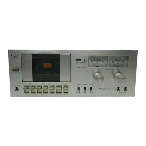
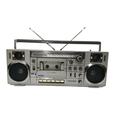
Sanyo M9930K User manual

CASSETTE
RECORDER
Recording
system
Erasing
system
Tape
speed
Rewind
&
Fast
forward
time
Wow
&
Flutter
Power
output
Frequency
range
AC
bias,
1/4
track
stereo
DC
erase
1-7/8
ips.
(4.75
cm/s)
Rewind:
1/30”
(C-60)
Fast
forward:
3'40’’
(C-60)
0.3%
RMS
2W
x
2
(maximum)
MW:
530
—
1,605kHz
FM:
83.5
—
108MHz
SW1:
2.3
—
7.0MHz
SW2:
7.0
—
22MHz
SPECIFICATIONS
Terminal
impedance
Frequency
response
Power
source
Dimensions
Weight
*
Specifications
subject
to
change
without
notice.
EXT.
MIC:
6k
ohms
REC/PB:
Input
10k
ohms
Output
1k
ohms
EXT.
SP:
4
ohms
HEADPHONE:
8
ohms
50
—
12,000Hz
DC:
9V,
UM—1
(D)
x
6
AC:
120/200/240V
50/60Hz
18-1/6'(W)
x
4-7/16"(D)
x
10-7/16’'(H)
(458
x
111
x
265
mm)
Approx.
10
Ibs.
6
ozs.
(4.7kg)
including
batteries
WM-3092

ADJUSTMENT
OF
PINCH
ROLLER
1.
Set
the
unit
to
the
PLAY
mode.
2.
Apply
a
tension
gauge
to
the
pinch
roller.
Read
the
gauge
at
the
precise
moment
when
the
pinch
roller
separates
from
‘the
capstan.
3.
if
the
gauge.
reading
is
within
a
range
of
450—650g,
no
adjustment
is
necessary.
!f
otherwise,
make
adjustment
by
changing
the
force
of
the
spring
coil.
(See
exploded
view
No.15)
Fig.1
ADJUSTMENT
OF
HEAD
AZIMUTH
1.
Connect
the
unit
to
a
power
source
and
insert
a
test
cassette
tape
(7K
Hz
pre-recorded)
in
the
cassette
compartment.
2.
Connect
an
4
ohm
dummy
load
with
the
VTVM
across
it
to
the
EXT.
SP
jack
on
the
unit.
3.
Set
the
unit
into
the
PLAY
mode
4.
Turn
the
head
azimuth
adjusting
screw
until
the
maximum
value
with
reading
on
the
VTVM.
5.
Fasten
the
adjusting
screw
securely
by
applying
paint
or
glue.
|
|
CLOCKWISE
COUNTERCLOCKWISE
ail
Oh
=
7
RECORD/PLAY
Head
(6)
S
iS
Auto
stop
lever
(11)
»~
Sy
BUGIS
oS
Ai
YZ
S|
<e
Coil
spring
(5)
AUTO-STOP
ADJUSTMENT
Measure
the
senser
pressure
with
a
tension
gauge
with
the
unit
set
in
the
playback
mode.
The
unit
should
be
shut
off
when
the
senser
pressure
stand
within
a
range
of
30
to
55
grams.
(Fig.
3)
If
the
shut-off
mechanism
fails
to
function
at a
senser
pressure
of
30
to
55
grams,
adjust
the
spring
coil
(Mechanism
No.
60).
Pinch
roller
lever(15)
Draw
the
slowly
in
a
horizontal
plane
Fig.3
MECHANICAL
ADJUSTMENT
To
measure
the
torque
of
the
tape
recorder,
a
torque
gauge
(Fig.
4)
and
a
tension
gauge
are
necessary.
To
use
a
tension
gauge,
make
a
hole
in
the
side
of
the
Cassette
as
shown
in
Fig.
5.
Be
careful
that
the
tape
does
not
rub
against
the
edge
of
the
Cassette;
these
will
make
correct
measurement
impossible.
1.
Take-up
torque
(measure
with
torque
gauge)
Play
30~65
gr/cm
Fast
forward
60~110
gr/cm
Rewind
60~110
gr/cm
2.
Back
tension
(measure
with
tension
gauge)
Play
Less
than
5
gr/cm
Fast
forward
Less
than
5
gr/cm
Rewind
Less
than
5
gr/cm
a
‘io
SAE
;
:
i
'
Tension
gauge
Cassette
tape
Tension
gauge
Fig.5

syd
CORDS
URONIC
ING
4
Turns

PARTS
LOCATION
Th
Ti
lili
©O}%3.,
CT-4(sW1)
FM—
MW—
SWI—
SW2
L106
L113
swi
eT
4
O
©
‘els
6!
10
-
FINE
So
pO
GTeg
TUNING
ee
CT-7
Sle
7301
MW
acs
|)
]1304
@TP-4
|@]r305
Lo
Oy
19
KHz
a
FZr-93
10K(B)
—
T
303
IC
501
Q)
TP-3
©
(S—
R311
270
LED(-)
LED(+)
MPX
LED
SW2
ALIGNMENT
Connections
VTVM
Oscilloscope
Adjusting
ice
SG
frequency
Position
of
tuning
dial
Adjustment
circuit
Output
6.8
MHz
(400
Hz
30% Low
end
of
dial
scale.
Connect
AM
SG.
modulation)
to
ANT
terminal
Connect
VTVM
to
through
|RE
EXT.
SP.
Terminals
22.5
MHz
dummy.
(400
Hz
30%
High
end
of
dial
scale.
modulation)
8.0
MHz
.
3
Connect
AM
SG.
inseaeetanl
8.0
MHz
on
dial
scale.
NT
to
ANT
termina!
Connect
VTVM
to
ANT.
|
through
IRE
EXT.
SP.
terminals.
Sane
|
A
dummy.
(400
Hz
30%
21.0
MHz
on
dial
scale.
modulation)
Repeat
adjustments.
PREPARE:
1.
Set
the
Fine
tuning
to
mechanical
center
at
cover
adjust.
4.
Use
screwdriver
with
plastic
for
all
adjustments.
2.
Set
the
dial
pointer
to
very
left
line
dial
scale.
5.
Selector
switch
to
“SW2".
3.
Connect
signal
generator
to
dummy
antenna.

TUNER
ADJUSTMENT
MW
ADJUSTMENT
Adjusting
-
Sega
VTVM
swe
|
Scheu?
[apa
Oot
xsl
aaa
RU
acca
Connect
sweep
455
KHz
Low
end
of
dial
scale.
1.F.T.
generator
to
(400
Hz
30%
At
position
of
1304305
MAX.
Test
Loop.
modulation)
unrequired
signai.
T306
505
KHz
{400
Hz
30%
Connect
AM
SG
to
Test
Loop.
Connect
oscilloscope
to
EXT.
SP
terminals
Low
end
of
dial
scale
Connect
VTVM
to
modulation)
speaker
terminals.
1650
KHz
(400
Hz
30%
modulation)
High
end
of
diai
scale
600
KHz
(400
Hz
30%
modulation)
600
KHz
on
dial
scale
Connect
AM
SG
to
Test
Loop.
Connect
VTVM
to
speaker
terminals.
1400
KHz
(400
Hz
30%
modulation}
1400
KHz
on
dial
scale
Repeat
adjustments.
PREPARE:
1.
Set
the
dial
pointer
to
very
left
line
of
diai
scale.
3.
Selector
switch
to
“MW”.
2.
Connect
sweep
generator,
AM
SG,
VTVM
and
oscilloscope.
4.
Use
a
screwdriver
with
plastic
grip
for
all
adjustments.
Connections
.
;
VTVM
Duigut
SG
frequency
Position
of
tuning
dial
|
Adjustment
Oscilloscope
Set
center
T301,T302
position
Near
max.
capacity
of
of
ceramic
VC.
at
positon
with
unrequired
signal.
FM
ADJUSTMENT
Adjusting
LF,
Connect
sweep
generator
to
Test
point.
2
Ratio
Det.
L104-1,2
TP1(H),
TP2{E)
3
OSC.
4
PREPARE:
1.
Set
the
dial
pointer
to
very
left
line
of
dial
scale.
3.
Use
a
screwdriver
with
plastic
grip
for
all
adjustments.
2.
Connect
sweep
generator,
FM
SG,
VTVM
and
4,
Set
center
position
of
ceramic
filter.
oscilloscope.
FM
antenna
input
impedance
is
75
ohm.
SW1
ALIGNMENT
Connect
oscilloscope
to
TP3
(H),
Shield
case
(E).
10.7
MHz
(O%
modulation)
Connect
oscilloscope
to
R317(H),
Shield
case
{E).
87MHz
(400Hz
30%
modulation}
Low
end
of
dial
scale
Connect
FM
SG,
to
Test
point
TP1
(H),
TP2
(E).
Connect
VTVM
to
speaker
terminal.
109
MHz
(400
Hz
30%
modulation)
High
end
of
dial
scale
90MHz
(400Hz
30%
modulation)
90
MHz
on
dial
scale
Connect
FM
SG.
to
Test
point.
TP1
(H),
TP2
(E).
Connect
VTVM
to
speaker
terminal.
106
MHz
(400
Hz
30%
modulation)
106
MHz
on
dial
scale
VTVM
Oscilloscope
Adjusting
circuit
SG
frequency
Position
of
tuning
dial
Connect
AM
SG.
2.15
MHz
.
$m)
*
Connect
AM
SG.
(400
Hz
30%
Low
end
of
dial
scale.
Connect
VTVM
to
EXT.
SP.
terminals.
to
ANT
terminal
through
IRE
Test
Loop.
modulation)
7.3
MHz
(400
Hz
30%
modulation)
High
end
of
dial
scale.
2.5
MHz
(400
Hz
30%
modulation)
2.5
MHz
on
Gial
scate.
Connect
AM
SG.
to
ANT
terminal
Connect
VTVM
to
through
IRE
EXT.
SP.
terminals.
Test
Loop
6.5
MHz
(400
Hz
30%
6.5
MHz
on
dial
scale.
CT4
modulation)
a
Repeat
adjustments.
PREPARE:
1.
Set
the
Fine
turing
to
mechanical
center
at
cover
adjust.
3.
Use
screwdriver
with
plastic
for
all
adjustments.
2.
Set
the
dial
pointer
to
very
left
line
dial
scale.
4.
Selector
switch
to
“SW1".
=

EXPLODED
VIEW
(CABINET)
TF
0,0,"0,
va
PA
MPa.
28;
SOs

PARTS
LIST
141-6-132T-86000
|
Individua!
carton
Washer
2.5
x
5
x
0.5
141-G-144T-45500
|
Foam
plastic
case,
Right
Washer
3
x
8
x
1
141-6-144T-45600
|
Foam
plastic
case,
Left
Washer
3
x
10
x
0.5
141-6-4
10T-06500
|
Instruction
manual
Washer
3
x
8
x
0.5
141-6-23.1T-40600
|
Inner
polye
cover,
Set
141-2-457T-23000
|
Special
washer
141-2-453T-01700
|
Washer,
Fiber
3
x
10x
1
Pan
Hd
Screw
w/spring
washer
3x4
Pan
Hd,
tapping
screw
w/washer
3x6
Pan
Hd,
tapping
screw
w/washer
3x8
141-6-231T-10250
|
Inner
polye
cover,
AC
cord
4-241T-11176
Cassette
tape
C-12
4-243T-76401
|
Power
cord
4-243T-13001
|
Power
cord
Pan
Hd,
tapping
screw
w/washer
‘4-243T-11500
|
Power
cord
{
°
Bh
ee
4-243T-79100
|
Power
cord
ed
pen
ee
Pan
Hd.
screw
3
x
6
ELECTRICAL
PARTS
141-9-111T-09600
|
Cabinet
Assy
4-251T-74471
|
Power
trans
141-9-124T-09600
|
Top
lid
Assy
4-511T-08088
|
Meter
141-2-855T-19700
|
Spring
coil
4-151T-25400
|
Speaker
4cm
4
ohm
141-2-126T-09200
|
Back
lid
Assy
4-235T-51300
|
Socket
4P
Mic
4-235T-26873
|
Socket,
AC
141-2-135T-32271
|
Cover,
CA
socket
141-9-128T-03500
141-2-271T-14300
Battery
iid
Assy
Bracket
handle
141-0-171T-08700
|
Handle
Assy
4-151T-25200
|
Speaker
12cm
141-2-385T-02201
|
Bracket
MIC
4-153T-10400
|
Microphone
141-2-742T-10500
|
Lever,
Top
Sid
4-235R-15700
|
Socket,
Remote
123-2-472R-11100|
Lug,
Rod
ANT
123-2-411R-10900
|
Plate
nut
4-244T-03200
|
Telescopic
rod
ANT
141-2-163T-45500
4-235T-34600
|
Socket
141-2-163T-45600
141-2-163T-45700
141-9-163T-04
100
141-9-163T
-04101
141-2-385T-02600
141-2-132T-03800
141-2-163T-44500
Rotary
kob,
Tuning
Rotary
knob,
VR
Rotary
knob,
VR
Rotary
knob
Assy,
Tone
Rotary
knob
Assy,
Band
select
Bracket
Sign
window,
Voitage
select
Rotary
knob,
Fine
Turning
Ome
a
NNA
AANA
—_
AMP
PCB
ASSY
140-9-230T-79000
4-231T-70100
4-231T-70000
P.C
board
Assy,
AMP
Switch,
Mono/stereo
Switch,
AT-RA-TA
Sea
\jera
ese
eae
We
NAN
eee
4-231T-72100
|
Switch,
R/P
’
4-231T-75100
|
Switch,
R/P’
°°
4-23
1T-65200
|
Switch,
Beat
4-235T-51500
|
Socket,
Headphone
141-2-3671T-30500
|
Bracket
socket
4-235T-37900
|
Socket,
Mic
123-2-566R-12000
|
Tuning
Shaft
4-235T-38000
|
Socket,
Mic,
Ext
SP
x
2
141-2-742T-11600
|
Lever
R/P
select
4-235T-33000
|
Socket
DIN
141-2-361T-13600
|
Bracket
resister,
VR
4-235T-33300
|
Socket
DIN
5P
123-2-363R-10400
|
Bracket
capacitor,
VC
4-258T-07100
|
OSC
Coil
141-2-425T-00200
|
Hexagon
screw,
VC
4-252T-01015
|
Low
frequency
choke
141-2-742T-11700
|
Lever,
Band
select
4-236T-10271
|
Plug
4P
Mic
141-9-311T-05800
|
Chassis
Assy
4-236T-10273
|
Plug,
GP
head
Spring
plate,
R/P
select
Brucket,
capacitor
141-2-853T-49
100
141-2-363T-06700
4-236T-10293
4-222T-39580
Plug,
2P
motor
Semifixed
variable
resistor
SVR801
141-2-538T-08100
|
Draum,
VC
141-2-162T-13600
|
Lever
knob,
Stereo/Mono,
141-2-340T-00200
|
Rope
Radio
ON/OFF
141-2-851T-06300
|
Spring
coil,
Rope
IC
LA4112
SN
141-2-661T-24600
|
Pulley
Transistor
2SC1740$
141-2-567T-02100
|
Pulley
shaft
141-2-511T-12700
|
Pointer
141-2-513T-03300
|
Carriage
Transistor
25C
1740
R
141-2-146T-15400
Dial
scale
Q802,902
Transistor
2SC1740
S
LN
141-2-566T-04900
|
Tuning
shaft
Assy
0701
Transistor
2SB187
RED
141-2-322T-43800
|
Shield
plate
D703,704,
Diode
182473
141-2-447T-00200
|
Cushion
802
902
141-2-464T-08700
|
Fixer
803,903,
141-2-464T-20671
|
Fixer
D804,904
Diode
DS442
141-2-464T-21100
|
Fixer
D702
Diode
DS131
A
or
DS132A
141-2-472T-01001
141-2-447T-65000
aD]
WW
Bw
a
VO
D801,901
Diode
1188
FM1
or
1N60F
(CAPACITORS)
Ceramic
47PF
50V
Ceramic
100PF
50V
Lug
Cushion
10
x
30x
2
C709
C805,905,
Pad
Hd
tapping
screw
2.3
x
6
Pan
Hd
tapping
screw
2.3
x
8
Saace.
Pan
Hd
tapping
screw
3
x
8
C841.941.
Ceramic
150PF
50V
Pan
Hd
tapping
screw
3
x
20
Pan
Hd
tapping
screw
3
x
25
Pan
Hd
tapping
screw
3
x
45
Hexagon
Nut
3mm
Hexagon
Nut
9mm
Ceramic
330PF
50V
+10%
Ceramic
470PF
50V
+10%
C812,912
C845,945,
707,708,
820,920,
844,944
away
Q
—
fh
—
|
fe)
|
etdand
gaat
ending,
.
\
Mebane
%
ateeio
1s
cbdead
int

2ARTS
LIST
AMP
PCB
ASSY
AMP
PCB
ASSY
Ref.
set
Ref.
a3
No.
ee
Ret
|
partnc,
|
aseription
ary
C942
Ceramic
560PF
50V
+10%
C835,935
Ceramic
680PF
50V
+10%
C825,925
Ceramic
0.001uF
50V
+10%
816,916
C831,931
Ceramic
0.0015uF
50V
+10%
C713,714,
Ceramic
0.01uF
50V
716
+80
—20%
C703,
704,
Ceramic
0.022uF
50V
+80—20%
701,702
C946,710,
Mylar
0O.001uF
SOV
+20%
836,936,
837,937,
846
C803
,903
Mylar
0.0022uF
50V
+20%
C808,908,
Mylar
0.01uF
SOV
+20%
809
909,
838,938
C711
Mylar
0.022uF
50V
+20%
C833,933
Mylar
0.15uF
50V
+20%
C801,901
Mylar
0.033uF
50V
+20%
C802,902
Al
Electrolytic
O0.1uF
10V
+40
—20%
C806,906,
Al
Electrolytic
0.22uF
10V
847,947
+40
—20%
C819,919
Al
Electrolytic
O0.33uF
10V
+40
—20%
C810,910,
Electrolytic
1uF
16V
811,911,
818,918,
814,914,
815
C824,924,
Electrolytic
2.2uF
16V
804,904
C826,926
Electrolytic
4.7uF
16V
C827,927,
Electrolytic
22uF
10V
712
C716,839,
Electrolytic
100uF
10V
939
C720
Electrolytic
100uF
16V
C929,843,
Electrolytic
220uF
10V
714,817,
917,828,
928,829
.
C705
Electrolytic
220uF
16V
C834,934,
Electrolytic
1000uF
10V
715
C706
Electrolytic
2200uUF
16V
C840,940
Electrolytic
4.74F
25V
(Nonpolar)
(RESISTORS)
R807
,907
Carbon
15
ohm
+10%
1/4W
R708
Carbon
220
ohm
+10%
1/4W
R825,925
Carbon
390
ohm
+10%
1/4W
R813
Carbon
1.5K
ohm
+10%
1/4W
R832,932
Carbon
3.3K
ohm
+10%
1/4W
R814,914,
Carbon
4.7K
ohm
=
+10%
1/4W
809,909
R810,910
Carbon
5.6K
ohm
+10%
1/4W
R802,902,
Carbon
6.8K
ohm
+10%
1/4W
805,905
R811,911
Carbon
8.2K
ohm
+10%
1/4W
R808,908
Carbon
22K
ohm
=
+10%
1/4W
R710
Carbon
68K
ohm
=
+10%
1/4W
R839,939
Carbon
100K
ohm
+10%
1/4W
R935,804,
Carbon
220K
ohm
+10%
1/4W
904,816,
916
R806,906
Carbon
820K
ohm
+10%
1/4W
R812,912
Carbon
1M
ohm
+10%
1/4W
R706
Carbon
270
ohm
+10%
1/4W
R801,901,
Carbon
3.9K
ohm
+10%
1/4W
831,931
R838,938
Carbon
120K
ohm
+10%
1/4W
R803
,903
Carbon
2.2Mohm
+10%
1/4W
R705
Carbon
8.2
ohm
+10%
1/4W
R821,921
Carbon
56
ohm
+10%
1/4W
2
1
2
1
2
4
2
4
2
2
71
2
5
NO
—
NAO
NN
R829,929
Carbon
1200hm
+£10%
1/4W
R819,919
Carbon
270
ohm
£10%
1/4W
|R818,918,
Carbon
1K
ohm
+10%
1/4W
R830,930
837,937
Carbon
100K
ohm
+10%
1/4W
823
,923
|
Carbon
2.2K
ohm
+10%
1/4W
Carbon
6.8K
ohm
+10%
1/4W.
BON
Ww
wW
ANN
>
R703,715
Carbon
8.2K
ohm
=
+10%
1/4W
R915,815
Carbon
68K
ohm
£10%
1/4W
R817,917,
Carbon
560K
ohm
+10%
1/4W
822,922
R711
Carbon
15
ohm
+10%
1/4W
1
TUNER
PCB
ASSY
63
140-9-230T-80900
{|
P.C.
Board
Assy,
Tuner
1
L111
4-257T
-26001
ANT
Coil
Assy
1
L110
4-257R-26930
|
ANT
Coil
1
L114
4-258T-05640
|
OSC
Coil
1
L113
4-258T-07640
|
OSC
Coil
1
L112
4-258T-18730
|
OSC
Coil
1
VCi~4
4-224T-10400
|
Variable
capacitor
J
VC5
4-224R-20700
|
Fine
Tuning
1
CT1~8
4-224R-11671
|
Trimmer
8
L101
4-265R-11600
|
VHF
Coil
1
L102
4-265R-11600
|
VHF
Coil
1
L103
4-265R-01200
|
VHF
Coil
1
L105,115
4-265R-05000
|
VHF
Coil
2
L106
4-265R-10500
|
VHF
Coil
1
L107,108
4-253R-11160
|
RF
Choke
2
L104-1
4-265R-13400
|
VHF
Coil
1
L104-2
4-265T-02100
|
VHF
Coil
1
L109
4-255R-10700
|
Choke
Coil
sae
T301
4-256R-20831
1
T302
4-256R-15131
1
T303
4-256R-02331
1
304,305
4-256R-00131
2
T306
4-256R-00231
1
4-256T
-80400
4-256T
-80471
4-256T
-80472
4-256T-80473
4-256T-80474
CF301
$1
4-231T-69300
|
Switch
1
B101
123-2-471R-10900
|
Core
1
CR501
502
4-227T-01400
|
CR
Pack
ae
9
4-227T-01410
|
CR
Pack
1
R503
4-222T-39475
|
Semifixed
variable
resistor
10K-B
Variable
resistor,
Volume
Variable
resistor,
Tone
Shield
plate
Shield
plate
Shield
plate
4-222T-61100
4-222T-61200
141-2-322T-18100
141-2-322T-18900
141-2-322T-40300
1
1
1
,
1
Q101
Transistor
2SC930
ER
1
-Q102,301
Transistor
2SC930
D
CONV
2
D302
,303
Diode
1$188
FM1
2
D301
Diode
18188
or
1N60
AM
1
D102
Diode
1$553
1
D304
Diode
YZ047A
1
D305
Diode
MV11T
1
D101,103,
Diode
1$2473
4
104,501
1C501°
1.C.
HA11227
1
1C301
sete
1.C.
MPC1018C
E
or
F
RESISTORS
Carbon
270K
ohm
+10%
1/4W
Carbon
47K
ohm
+10%
1/4W
Carbon
3.3K
ohm
+10%
1/4W
Carbon
1K
ohm
+10%
1/4W

PARTS
LIST
Pree
[raeme.
[Daron
TUNER
PCB
ASSY
Ref.
a
TUNER
PCB
ASSY
R306
Carbon
560
ohm
+10%
1/4W
|
1
€112,120
Ceramic
0.047uF
50V
+80
—20%
R303,307,
Carbon
220
ohm
+10%
1/4W
|
3
C848,948
Ceramic
0.0022uF
50V
+10%
308
€322:323,
Mylar
0.01uF
50V
+20%
R304
Carbon
150
ohm
+10%
1/4W
|
1
C502,821,
Mylar
0.047uF
50V
=
+
20%
R116
Carbon
82
ohm
+10%
1/4W
1
971
R115,518
Carbon
47
ohm
+10%
1/4W
|
2
C136,309
Mylar
0.022uF
50V
+20%
R311
Carbon
270
ohm
+10%
1/4W
)
1
C329
Mylar
0.022uF
50V
+20%
R321
Carbon
33K
ohm
+10%
1/4W
|
1
C316,128,
Mylar
0.0033uF
50V
+20%
R515
Carbon
1K
ohm
+10%
1/4W
1
823.923
R310
Carbon
390
ohm
+10%
1/4W
1
C137
Mylar
0.0047uF
50V
+20%
R505,506
Carbon
3.3K
ohm
+10%
1/4W
2
C302
Mylar
0.022uF
50V
+20%
R107
,836,
Carbon
2.2K
ohm
+10%
1/4W
3
C127
Mylar
0.0047yF
5O0V
+20%
936
C325
Mylar
0.01
uF
+209
R516
Carbon
220
ohm
+10%
1/4W
1
C305
Mylar
0.022uF
50V
20%
R312
Carbon
560
ohm
+10%
1/4W
j
C327
Mylar
0.022uF
50V
+20%
R325
Carbon
120
ohm
210%
1/4W
|
|
C822,922
Mylar
0.068uF
50V
=
+20%
R327
Carbon
1M
ohm
#10%
1/4W
|
1
C324,511
Electrolytic
470uF
10V
R110,326
Carbon
100K
ohm
+10%
1/4W
2
C319
Electrolytic
47uF
6.3V
R102.105,
|
Carbon
15K
ohm
+10%
1/4W
|
4
C312
Electrolytic
4.7uF
6.3V
309,319
C317
Electrolytic
10uF
6.3V
R302,504
Carbon
18K
ohm
+10%
1/4W
|
2
C509,510
AL
Electrolytic
0.1uF
10V
R330,824,
Carbon
15K
ohm
+10%
1/4W
3
+40
—20%
924
C503
Electrolyti
9
R328,517
Carbon
1K
ohm
+10%
1/4W
|
2
C501
ecreiyue
lowe
10
R315,316,
Carbon
5.6K
ohm
+10%
1/4W
4
C130
Styrol
1400PF
50V
+5%
317,504
C506
Styrol
470PF
50V
+5%
R509
507
Carbon
5.6K
ohm
+10%
1/4W
|
2
C504,505
AL
Electrolytic
O.22uF
16V
+20%
R324,508,
Carbon
2.2K
ohm
10%
1/4AW
|
3
C306
,321
Mylar
0.047uF
50V
+20%
510
C507,508
Mylar
0.015uF
50V
+20%
R510,513
Carbon
1K
ohm
+10%
1/4W
|
2
C512
Electrolytic
1uF
10V
R305
Carbon
220
ohm
+10%
1/4W
|
1
C505
AL
Electrolytic
2.2uF
16V
R101,104
Carbon
470
ohm
410%
1/4W
2
+40
—20%
R512
Carbon
390
ohm
+10%
1/4W
1
R301
Carbon
330
ohm
+10%
1/4W
1
R108
Carbon
100
ohm
+10%
1/4W
1
R109,111,
Carbon
56
ohm
+10%
1/4W
|
4
LED
PCB
ASSY
118,331
R103
Carbon
33
ohm
+10%
1/4W
1
R511.322
Carbon
47
ohm
+10%
1/4w
|
2
140-9-230T-81000
|
P.C.
Board
Assy,
LED
R117
Carbon
68
ohm
+10%
1/4W
|
1
0501
LED
SLP
224B
Red
R319
Carbon
15K
ohm
+10%
1/4W
|
1
141-2-352T-21500
|
Spacer
CAPACITORS
C307
Ceramic
1PF
50V
+0.25PF
1
C122
Ceramic
2PF
50V
+0.25PF
1
C129
Ceramic
3PF
50V
+0.25PF
1
C304
Ceramic
4PF
50V
+0.25PF
1
C131,115
Ceramic
5PF
50V
+0.5PF
2
C109,124,
Ceramic
6PF
50V
+0.5PF
3
108
C123
Ceramic
8PF
50V
+0.5PF
1
C136
Ceramic
10PF
50V
+10%
1
_
C121,125
Ceramic
1OPF
50V
+10%
2
C121,125
Ceramic
10PF
50V
+10%
2
C116
Ceramic
12PF
50V
+10%.
1
C134
Ceramic
12PF
50V
+10%
1
C103
Ceramic
15PF
50V
+10%
1
C101,107
Ceramic
20PF
50V
+10%
2
C308
Ceramic
30PF
50V
+10%
1
C110
Ceramic
30PF
50V
+10%
1
C310,311
Ceramic
220PF
S0V
+10%
2
C111
Ceramic
330PF
50V
+10%
1
C313
Ceramic
100PF
50V.
+10%
1
C133
Ceramic
10PF
50V
+10%
1
C102
Ceramic
30PF
50V
+10%
1
C104
Ceramic
470PF
50V.
+10%
1
C105,106
Ceramic
0.001uF
50V
+10%
2
C303
Ceramic
0.01uF
50V
+80
—20%
1
C113,114,
Ceramic
0.01uF
50V
+80
—20%
3
301
C331
,314,
Ceramic
0.022uF
50V
+80
—20%
3
320
C328
Ceramic
0.022uF
50V
+80
—20%
1
C117,326
Ceramic
0.047uF
50V
+80
--20%
2
C118
BC-CON
0.1uF
12V
+20%
1
C332,333
Ceramic
0.022uF
50V
+80
—20%
2
C315
Ceramic
0.01unF
50V
+80
—20%
1

PARTS
LIST
MECHANISM
Ret
|
paene,
|
Oaeerinon
jy
141.0-311T-23491
141-2-853T-46900
141-2-375T-06900
141-2-821T-10700
141.2-851T-82700
4-242T-21671
4-242T-19500
123-2-472R-00200
141-2-472T-02200
141-2-721T-03900
141-2-731T-37500
141-2-852T-35300
141-2-853T-53
200
141-0-545T-02900
141-2-461T-28400
141-0-521T-06500
141-0-524T-02900
141-2-742T-08200
141-2-851T-80100
141-2-741T-96400
141-2-855T-10800
141-2-661T-65701
141-2-661T-65702
141-2-661T-65704
141-2-661T-65705
141-2-661T-65706
4-527T-08371
141-2-421T-12501
141-2-445T-07000
141-2-564T-15401
141-2-564T-16500
141-0-661T-02400
141-2-853T-48000
141-2-457T-06200
141-2-531T-10101
141-2-531T-09900
141-0-661T-02300
141-2-661T-23001
141-0-741T-22100
141-2-661T-22600
141-2-161T-47100
141-2-322T-34400
141-2-855T-01900
141-2-851T-96200
141-2-851T-12400
141-9-161T-03000
141-9-161T-03001
141-2-731T-43301
141-2-851T-73500
141-2-731T-43401
141-2-851T-93000
141-0-731T-13700
141-2-851T-91300
141-2-851T-96400
141-0-731T-13800
141-2-731T-73701
141-2-851T-93000
144-2-731T-43101
141-2-855T-00200
141-2-731T-51101
141-2-855T-00601
141-8-731T-14000
141-2-851T-92700
141-2-741T-78400
141-2-851T-91200
4-231T-61600
4-231T-59700
141-2-741T-61000
141-2-851T-87701
141-2-742T-08100
141-2-851T-56100
141-0-731T-14100
141-2-614T-05200
141-2-852T-37900
141-2-742T-01400
141-2-457T-04300
123-2-472R-00400
141-2-322T-27100
Chassis
Assy
Spring
Plate,
Cassette
Plase
Bracket
Head
Tape
Guide
Spring
Coil
R/P
Head
Head
R/P
Head
E
Lug
Lug
Lever
Shaft-Off
Slide,
Head
Base
Spring
Wire,
Pinch
Roller
Spring
Plate,
Head
Slide
Lever,
Pinch
Roller
Pipe
Fiywheel
Assy
Bracket
Flywheel
Assy
Lever
Spring
Coil
(T012)
Lever,
Cassette
Up
Spring
Coil
Pulley
Pulley
Pulley
Pulley
Pulley
Motor
Special
Screw
Rubber
Cushion,
Motor
Square
Belt,
Main
Belt
Pulley
Assy,
Supply
Spring
Plate
Special
Washer
Reei
Plate,
Suppiy
Reei
Plate,
Tackup
Pulley
Assy,
Tackup
Pulley,
Tackup
Lever
Assy
Pulley,
REW
Push
Button,
FWD,
REW,
PLAY
Shieid
Plate
Spring
Coil
Spring
Coil
}or
Spring
Coil
Push
Button
Assy,
Stop
Push
Button
Assy,
Rec
Slide,
Stop
Spring
Coil
(T433)
Siide,
FWD
Spring
Coil
(T-434)
Slide
Assy,
PLAY
Spring
Coil
Spring
Coil
Slide
Assy,
REW
Slide,
REC
Spring
Coil
Slide,
Brake
Spring
Coil
Slide,
PLAY
Spring
Coil
(7-511)
Slide
Assy
Spring
Coil
(T-478)
Lever,
Auto-Stop
Spring
Coil
Switch,
Power
Switch
Power
Lever
Spring
Coil
(T-610)
Lever,
Stop/Play
Spring
Coil
(T-91
1)
Slide
Assy,
PAUSE
Lever
Lock,
PAUSE
Spring
Wire,
(T-052)
Lever,
PAUSE
Special
Washer
Lug
Shield
Plate
or
mee
wee
keke
ek
A
ek
we ed
wt
et
we
wt
—
Ga
ot
os
—
=
ot
A)
OO
=
=
ADA)
=
—_
=—_h
—_
G)
md
—
3
2
se
ne
et
eek
ee
et
=
fA)
=
A
=
—
A}
Oe
i
St
Oe
MECHANISM
141-2-161T-47400
141-2-351
T-42800
141-2-811T-05400
141-2-812T
-06300
141-2-564T-16900
141-2-464
T-08700
4-235T-34600
4-235T-51400
141-2-457T-23700
141-2-457T-23000
141-2-457T-23200
141-2-345T-00400
141-2-457T-11000
141-2-453T-30101
141-2-453T-31200
141-2-453T-30201
141-2-453T-30202
141-2-453T-30802
141-2-453T-00800
141-2-447T-36000
141-2-488T-01801
141-2-490T-00500
141-2-490T-00600
141-2-184T-01900
Push
Button,
PAUSE
Bracket
Mtg.
Counter
Bracket
Counter
Square
Beit
Fixer
Socket
Head
x
2,
SW
x
2
Socket
R/P
Head
Lead
Pan
Hd.,
Screw
2
x
2
Pan
Hd.
Tapping
Screw,
W/Washer
2x
12
Pan Hd.
Screw
2
x
12
Pan Hd.
Tapping
Screw
3
x
20
Pan
Hd.
Tapping
Screw
2.3
x
8
Pan
Hd.
Tapping
Screw
3
x
6
Pan Hd.
Tapping
Screw
3
x
8
Pan
Hd.
Tapping
Screw
3
x
6
Pan Hd.
Tapping
Screw
3
x
8
Washer
2.5
x5
x
0.5
Washer
3
x
8
x
0.5
Flat
Hd.
Wood
Screw
3
x
12
Washer
4
x
10x
0.8
Spring
Washer
2
x
4.4
x
0.5
Special
Washer
Special
Washer
Special
Washer
Stee!
Ball
Special
Washer
Washer
2.1
x
4
x
0.25
Nylon
Washer
2
x
8.5
x
0.25
Washer
2.5
x
5
x
0.25
Washer
2.6
x
4.7
x
0.5
Washer
6.2
x
9.5
x
0.5
Washer
3x8
x
0.5
Cushion
Pini1.5x8x0.3
Headless
Screw
2
x
4
Tube
Tube
Tube
Tape
Washer
3
x
12
x
1.2
Flat
Hd.
Screw
3
x
8
Pan
Hd.
Tapping
Screw
W/Washer
3x8
awit
=
PAQ
a
asa
BNW
=|@=
SBD
AN
HAHN
AWNHOHWHWHNNARAANWHWAHW

EXPLODED
VIEW
(MECHANISM)
ge
Y1I5—®
&—yI5
—10—
EXPLODED
VIEW
(CHASSIS)
—11—
ee
a
meee
ea
ORT
ES
eT
et
ee
eT

SCHEMATIC
DIAGRAM
(TUNER)
|
Q
101
2SC930E
ROD
ANTENNA
Q
301
2SC930
D
O.35V
CF-301
R306
560
CC
Ae
ses
C303
0.01
R308
220
L103
6104
“0
470P
R103
33.
C108
6P
}
—
®,
|
(C301
R301
eee
C103
15P
ypu
re
R307
220
o
ne
-
ane
ey
re
S
i
eel
es
a
§
C115
5P
°
Tae
©
wae
aan
©
es
O
acai
7
:
ym
oa
42V
ro)
xe
1°
573
:
gsi.|
|x|
18
So
®
e
=
eile
S
B|
&
=
=
ip
4.7/6.3
|V
a
.
q
“LW
©
©
|
O
Oo
5
=
wt
OW)
=
|
4
2
Zl
a)2
oa
te
S
IC
301
Q)
ev
©
=
-|
Ss)"
=|o|
|z
PC
1018C
:
tr
|
oO
-|<
~
Se
V|a
S
OV
B
oy
(2)
2
ro)
|
aD
a
J
Ly
ro)
(6)
co
OV
vO
R108
100
R109
56
a
ee
ee
(ase
s=20)
~
x
One
Te
ee
ee
C304
4P
C305
0.01
x
NOV
or
i
aa
en
eres
aed
10304]
YZ-047A
|
i
iP
QIt
|
[8
©
R319
15K
ae
R303
220)
Ye
t
Wo
oe
f
es
ihe
|
TO
S
©
x<
pegged
ec
UE
gees
ak
aS
Oo
oF
Tae
ES
D305
c
T3072
T305
=
pa
i
3
R321
33K
©
N
2
2
jal
Lc32i
aah
:
ae
eee
es
a
T.2V1
|
|
C328]
0.022
C128
0.0033
R326
100K
z=
Sesaeeeea!
.
R515
_15K
ieee
Gees
Be
$763
ss
[3
ae]
ue
aoa
T
[care
on
me
[}—w-—
reer,
1)
=
co)
os
N
NO
(
z
i>
1}
RIS
S|
<x
ee
7
ey
me
hav]
!
;
vx
Sel
ol
8
are
am
|
ov
D
C503
1p/10
a
!
o
‘
5
o
AJIQKHZ
:
:
Se
O
>
se
=
|
sw24
2,
SW2_
SW2]
C130
SW,
7
TP.
4
xx
=
5s
be
h'5
C511
470p/10V
°F
99
ue
273
|
=
|
Sswi]
BT
bry
ala
SW1-
|
C
©
C502
=
m
—
Wweeowi
Cc
oy
.
@
|
Swi
el
|
am
O@
O00
|
=
0.047
§
.
;
hl
R508
2.2K
!
Pc
|
cP
D104
L113,
1S
LQ
swi]
MWFM]
o
a
$4
z
@
a.
1$247
es
|
S1i-10
|
ia
wa
MW
or wn
LEFT
|
olo
|°
|
O
wae
alten
ecto
|
.
.
5
MWe
|
lex
We
|
ca
OV
13)-15)-04){9)
!
O
I
a.
S17
S156
=e
ftal
alba
|
HA11227
S
=
re
a
©
|0.5V
wn
|
a
1
|
=
ics
~
V
RIGHT
[|
To)
C132
aw
Sen
!
|
|
Bs
ILai-b
—
|Z
340P
(S)
aie
Sate:
A
|
=
=
7B
fe,
ital
=
;
x
R510
2.2K
©
a.
wm
ro)
a.
-
-
S
_
2
I
~“
C501
10/10
2
2yli0V
Z
7
gi
ve
3
Be
lus
22.7137
LS
3
3
|
=
|
oa
ae)
1
32.
:
ee
2)
D
|
Oo
S
=
alo
--}e
2
2
2
ta
ree
eT
ee
ee
eeu
R512
390
~—s-
R's
O
MW
eer
D502
1$2473
;
B
Oo
SWI
EC
Oo
sw2
BAND
SW
S1-1~S1-10
—12—
;
—13-

WIRING
DIAGRAM
(TUNER
ROD
ANTENNA
anton
GeO”
LeU
Ze
Be
zs
ee
es
LEFT.IN
LEFT.
OUF
oe
EERE
aI
oe
RIGHT.
IN
—
oa
~~
#.
|
FROM
AMP
V
RIGHT.
OUT
ee
—
.
ee
fis
:
:
we
s
oe
ae
:
SS
*
_
|.
——
EARTH
y 3 : .
BETES
:
en
‘
: :
eB
rs
Pe
Si
j g
:
:
Seen
‘i
s z : :
on
fe
Be,
sh
é
3
is
i
i
ee
te
a
:
a.
fe
g
‘
&
ST/
MONO.
SWITCH
(.)
ST/MONOQ
SWITCH
eB
EARTH
FINE
TUNING
RIGHT.
SIG
LEF-T.SIG
45
|
=15-

SCHEMATIC
DIAGRAM
(AMP)
R838
120K
/
Ti
Q801
Q802
Q803
Q804
|
Q805
2SC1740
S
2SC1740
LNS
25C1740
S
2SC1740
S
2SC1740
S
.
[810.50
_V)
[B
[0.56
VI
[BL
0.58
V
|
[B
[0.98
Vv]
[B
[0.71
VI
re
ee
ee
>,
OUT
|
ELECTLET
Vee
—
als
aba
&
0703
3
$751
So
Us
P_s907
eee
aes
WOK
442
IN
S74)
R
e
e
a
ae
$701
©
C823
0.0033
D801
C814
lu
1S18BFI4
VR802
4
5OKB
R836
C822
2.2K
0.068
C816
0.001
R821
56
R825
C826
D802
DS442
+
C844 470P
C820
470P
L801
15mH
C716
100y/
10V
D804
DS442)
R832
3.3K
C839
100yu/10V
C837
0.001
£835
680P
D803
R829
MO
6S
DS442
120
4
$761
ALC
ELECTLET
MIC
C901
R931
IC901
LA4112
C923
C908
R911
R936
C922
x
D
ra)
(
2)
x
CSaae
ee
C942
560P
ssl
8
Ot
O
1
xd}
=Y
4
Be
|
N
os
!
is
ra
R708
390
>
©
wn
©
EH
¢)
si
8
25
°
baad
re
=w
Co
w
~-
-
x
o
Oo
=
—
N
f&
|
a{
OSC
COIL
x
=s
AC
IN
°o
~~
1
02
S
50/60Hz
S
a
w
S771
3}
R705
8:2
=
n
ro)
Sk
=
5
ov
VO
CY)
O
~~
Q701
Sees
Bese
ao
ape
anne
eer
a
ges
z
$731.
$701
—
$705----TAPE/RADOIO/TIMER
SWI
TCH(
S706
TUNER)
25B187
RED
698
besa
-esss
-
VOLTAGE
SELECT
SWITCH
|
Ee
$721--------
AC/DC
SWITCH
;
‘
rs18.2
VI
i
nee
POWER
SWITCH
STi
eso
2
MIC
SWICH(DIN
SOKET)
S75)
ees
MIC
SWICH
(MIC
SOKET)
25C1740
$761
—
$763---
MONO/STEREO
SWITCH
a
Bae
z
2
ope)
RECIPLAY
SWITCH
:
7B
$771
--------
BEAT
CANCEL
SWITCH
—16—
—17-
(3)R.
SIGNAL
(2)
L.
SIGNAL
R710
68K
\3V
0.224/16V
WOOFER
4
OHM
b=CH
TWEETER
4
OHM
TWEETER
4
OHM
WOOFER
4
OHM
a
i
a
a
aad

WIRING
DIAGR
AM
RIGHT
OUT
VaR
Leer
OUT
ee
AMP
REGHT
IN
ae
VR
EEF
T
IN
249=
Ses
|
=
-
Snare
eT
TE
nTTTTTETTET
TE
ETTEETTIDETOSIOyOT
TTT
ners
TIT
err
re
eomenbeenaesaaeememmmeaeemeneeeemmenemenmenenmeenmmmemnanaell
Pol
fem
ee
ee
te
Soe
e
Ld
CMI
@
Mic
Urea
MIC
RIGHT
EXT.
SP
LFET
WOOFER
RIGHT
TWEETER
RIGHT
WOOFER
eS
al
TWEETER
rey
Table of contents
Other Sanyo Cassette Player manuals

Sanyo
Sanyo JJ-P4 User manual

Sanyo
Sanyo MCD-Z165F User manual

Sanyo
Sanyo MCD-Z22L User manual
Sanyo
Sanyo MCD-Z330F User manual

Sanyo
Sanyo MCD-X75L User manual

Sanyo
Sanyo MCD-s900F User manual

Sanyo
Sanyo VHR-450 User manual

Sanyo
Sanyo MCD-Z12F User manual

Sanyo
Sanyo MCD-Z160F User manual

Sanyo
Sanyo MCD-ZX530F User manual

Sanyo
Sanyo dcf150 User manual

Sanyo
Sanyo MCD-Z31F User manual

Sanyo
Sanyo M7700L User manual

Sanyo
Sanyo VHR-I 50 series User manual

Sanyo
Sanyo TRC 8000 User manual

Sanyo
Sanyo MCD-S665F User manual

Sanyo
Sanyo MCD-s900F User manual

Sanyo
Sanyo MCD-Z330F User manual

Sanyo
Sanyo MCD-S665F User manual

Sanyo
Sanyo MCH-900F User manual