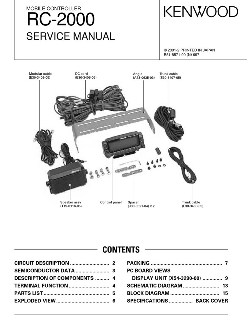
Kenwood KVC-470 User manual

AUDIO
VIDEO
SYSTEM
CONTROLLER
KVC-470
INSTRUCTION
MANUAL
KENWOOD
B50-5224-00
(U,
UE)
(G)
67890N/455
D12345/555

Introduction
The
purpose
of
this
manual
is
to
acquaint
you
with
the
operating
features
of
your
new
audio video
system
controller.
You
will
notice
that
in
every
detail
of
planning,
engineering,
styling,
operating
convenience,
and
adaptability,
we
have
sought
to
antici-
pate
your
needs
and
desires.
We
recommend
that
you
read
this
manual
carefully.
Knowing
how
to
set
up
your
controller
to
the
best
advantage
will
enhance
your
listening
pleasure
right
from
the
start.
You
will
also
become
aware
of
the
ease
with
which
you
can
adjust
your
controller
to
meet
your
special
requirements.
For
your
records
Record
the
serial
number,
found
on
the
back
of
the
unit,
in
the
spaces
designated
on
the
warranty
card,
and
in
the
space
provided
below.
Refer
to
the
model
and
serial
num-
bers
whenever
you
call
upon
your
dealer
for
information
or
service
on
this
product.
Model
KVC-470
Serial
number
Unpacking
Unpack
the
unit
carefully
and
make
sure
that
all
accessories
and
cables
are
put
aside
so
they
will
not
be
lost.
Examine
the
unit
for
any
possibility
of
shipping
dam-
age.
If
your
unit
is
damaged
or
fails
to
operate,
notify
your
dealer
immediately.
If
your
unit
was
shipped
to
you
directly,
notify
the
shipping
company
without
delay.
Only
the
con-
signee
(the
person
or
company
receiving
the
unit)
can
file
a
claim
against
the
carrier
for
shipping
damage.
We
recommend
that
you
retain
the
origina!
carton
and
pack-
ing
materials
for
use
should
you
transport
or
ship
the
unit
in
the
future.
Important!
U.S.A.
and
Canada
Units
shipped
to
the
U.S.A.
and
Canada
are
designed
for
operation
on
120
volts
AC
only.
These
units
are
not
equipped
with
an
AC
voltage
se-
lector
switch
and
the
discussion
of
such
a
switch
that
follows
should
be
disregarded.
All
other
countries
Units
shipped
to
countries
other
than
the
U.S.A.
and
Canada
are
equipped
with
an
AC
voltage
selector
switch
on
the
bottom
plate.
Refer
to
the
following
paragraph
for
the
proper
setting
of
this
switch.
Renae
a
Safety
precautions
CAUTION
stho)
GO]
aim
of
OOM
En
11
Ons)
0101014
DO.
NOT
OPEN
AC
voltage
selection
This
unit
operates
on
120
volts
or
220
volts
AC.
The
AC
voltage
selector
switch
on
the
bottom
plate
is
set
to
the
voltage
that
prevails
in
the
area
to
which
the
unit
is
shipped.
Before
connecting
the
power
cord
to
your
AC
out-
let,
make
sure
that
the
setting
position
of
this
switch
matches
your
line
voltage.
If
not,
it
must
be
set
to
your
vol-
tage
in
accordance
with
the
following
direction.
Note:
Our
warranty
does
not
cover
damage
caused
by
excessive
line
vol-
tage
due
to
improper
setting
of
the
AC
voltage
selector
switch.
]
AC
120V
~~
4p
220Vv
AC
120V
~
<p
220V~
©
LK
oe
AL)
©
This
shows
switch
lever
locked
in
the
220V~
position.
This
shows
switch
lever
locked
in
the
120V~
position.
I
Move
switch
lever
to
match
your
line
voltage
with
a
small
screw
driver
or
other
pointed
tool.
AC
voltage
selector
switch
|
WARNING:
TO
PREVENT
FIRE
OR
ELECTRIC
SHOCK,
DO
NOT
EXPOSE
THIS
APPLIANCE
TO
RAIN
OR
MOISTURE.
CAUTION:
TO
REDUCE
THE
RISK
OF
ELECTRIC
SHOCK,
DO
NOT
REMOVE
COVER
(OR
BACK).
NO
USER-SERVICEABLE
PARTS
INSIDE.
REFER
SERVICING
TO
QUALI-
FIED
SERVICE
PERSONNEL.
persons.
2
KVC-470(U}
The
lightning
flash
with
arrowhead
symbol,
within
an
equilateral
triangle,
is
intended
to
alert
the
user
to
the
presence
of
uninsulated
“dangerous
voltage”
within
the
product's
enclosure;
that
may
be
of
sufficient
magnitude
to
constitute
a
risk
of
electric
shock
to
The
exclamation
point
within
an
equilateral
triangle
is
intended
to
alert
the
user
to
the
presence
of
important
operating
and
maintenance
(servicing)
instructions
in
the
litera-
ture
accompanying
the
appliance.

Before
operation
Notes
on
installation
Do
not
place
the
unit
in
a
place
which
is
exposed
to
direct
sunlight,
near
a
heating
appliance,
etc.
O-
/
Hey
rag
Do
not
place
a
vase
containing
water,
makeup,
etc.
on
the
unit.
Do
not
use
in
a
humid
place.
>
To
maintain
good
ventilation,
do
not
put
records
or
a
table-
cloth
on
the
untit.
Place
the
unit
at
least
10
cm
away
from
the
walls.
Choose
a
location
that
is
relatively
free
from
vibration
or
ex-
cessive
dust.
@
Do
not
place
a
video
tape
deck
on
top
of
the
KVC-470,
The
deck
may
be
damaged
by
heat
from
this
unit.
@
When
operating
two
or
more
video
decks,
do
not
place
the
video
decks
close
each
other,
or
video
and
audio
sig-
nals
may
be
deteriorated.
@
When
a
video
deck
is
used
in
a
vicinity
of
a
TV
set
or
con-
trolier,
the
audio
signal
may
be
interfered
with
magnetic
field
generated
from
TV
set.
This
causes
noise
in
the
au-
dio
signal
and
stripes
on
the
picture.
In
this
case,
place
the
video
deck
away
from
the
TV
set.
Safety
precautions
Never
remove
the
case.
If
the
internal
parts
are
touched
ac-
cidentally,
a
serious
electric
shock
might
occur.
Never
touch
internal
parts.
Touching
the
power
plug
when
your
hands
are
wet
may
re-
sult
in
a
serious
electric
shock.
\
Gy
yw
:
yy
Never
touch
with
0)
wet
hands.
oO
5
Never
pull,
bend
or
extend
the
power
cord.
This
could
da-
mage
the
power
cord,
resulting
in
a
broken
cord
or
short-
circuit.
Always
grasp
the
“plug.
i
In
case
of
abnormal
smell
lf
an
abnormal
smell
or
smoke
is
detected,
immediately
turn
the
power
OFF
and
pull
out
the
power
cord.
Contact
your
dealer
or
nearest
Service
Station.
re
@
3
6
ia
==
Cleaning
Do
not
use
volatile
solvents
such
as
alcohol,
paint
thinner,
gasoline,
benzine,
etc.
to
clean
the
cabinet.
Use
a
silicone
cloth
or
a
clean
dry
cloth.
Silicone
Thinner Benzine
cloth
Kvc-470(u)
3

System
connections
TV
antennas
(VHF)
Monitor
TV
Videodisc
player
|
oO
ooooggguG
3
|
il
amplifier
—
(UHF)
Video
cassette
recorder
A
Video
cassette
(VCRA)
recorder
B
(VCR
B)
Television
set
KVC-470
To
AC
outlet
Exe)
=
=;
=
°
Speaker
system
Peto
at
alae
|
Turntable
Connection
of
video
decks
This
unit
is
equipped
with
the
VCR
A
and
VCR
B
jacks
for
connection
of
two
video
tape
decks.
These
jacks
can
be
used
for
playback
and
recording.
@
VCR
A
jacks
Video-path
connection:
Recording
—
Connect
the
VIDEO
REC
jack
of
this
unit
and
the
video
input
jack
of
video
deck
(VCR
A)
with
an
audio
cable.
Playback
—
Connect
the
VIDEO
PLAY
jack
of
this
unit
and
the
video
output
jack
of
the
video
deck
(VCR
A)
with
an
audio
cable.
Audio-path
connection:
Recording
—
Connect
the
AUDIO
REC
jacks
of
this
unit
and
the
audio
input
jacks
of
the
video
deck
(VCR
A)
with
an
audio
cable.
Playback
—
Connect
the
AUDIO
PLAY
jacks
of
this
unit
and
the
audio
output
jacks
of
the
video
deck
(VCR
A)
with
an
audio
cable.
4
Kvc-470{U)
Speaker
system
Ta
deck
Tape
deck
@
VCR
B
jacks
Video-path
connection:
Recording
—
Connect
the
VIDEO
REC
jack
of
this
unit
and
the
video
input
jack
of
the
video
deck
(VCR
B)
with
an
audio
cable.
Playback
—
Connect
the
VIDEO
PLAY
jack
of
this
unit
and
the
video
output
jack
of
the
video
deck
(VCR
B)
with
an
audio
cable.
Audio-path
connection:
Recording
—
Connect
the
AUDIO
REC
jacks
of
this
unit
and
the
audio
input
jacks
of
the
video
deck
(VCR
B)
with
an
audio
cable.
Playback
—
Connect
the
AUDIO
PLAY
jacks
of
this
unit
and
the
audio
output
jacks
of
the
video
deck
(VCR
B)
with
an
audio
cable.

Connection
of
videodisc
player
Video-path
—
Connect
the
VDP
VIDEO
jack
of
this
unit
and
the
video
output
jack
of
the
videodisc
player
with
an
audio
cable.
Audio-path
—
Connect
the
VDP
AUDIO
jacks
of
this
unit
and
the
audio
output
jacks
of
the
videodisc
player
with
an
audio
cable.
Videodise
player
Ch
EE
QO.
cgoo0ononDD
OO
Video-path
connection
Audio-path
connection
Videodisc
connection
Note:
1.
In
sorne
video
deck,
connecting
the
plug
into
the
REC
jack
auto-
matically
shut
off
the
built-in
TV
tuner
section
of
the
video
deck.
For
details
of
the
connection,
refer
to
the
Instruction
Manual
of
the
video
deck.
2.
When
connecting
a
monaural
video
deck,
set
the
MODE
switch
to
MONO.
Connection
of
TV
sets
@
With
conventional
TV
sets
(having
no
video
input
jack)
1.
Connect
the
VHF
antenna
output
terminal
of
the
video
deck
connected
to
the
VCR
A
jacks
and
the
VHF
IN
ter-
minal
of
this
unit
with
the
supplied
coaxial
cable.
2.
Connect
the
VHF
OUT
terminal
of
this
unit
and
the
VHF
antenna
input
terminal
of
the
TV
set
with
the
coaxial
cable
supplied
with
the
video
deck.
3.
Connect
the
UHF
antenna
input
terminal
of
the
TV
set
and
the
UHF
antenna
output
terminal
of
the
video
deck
with
a
UHF
ribboned
feeder
lead.
For
proper
connection,
consult
the
Instruction
Manual
of
your
video
deck,
ae
TV
antenna
Conventional
TV
set
UHF
-
To
VHF
output
To
VHF
antenna
terminal
terminal
Using
conventional
TV
set
@
With
monitor
TV
or
conventional
TV
equipped
with
the
video
input
jack
As
shown
in
figure
below
connect
the
VIDEO
OUT
jack
of
this
unit
and
the
video
input
jack
of
the
TV
set
with
an
audio
cable.
Audio
cable
equipped
with
pin
plug
on
each
end
Monitor
TV
set
Monitor
TV
connection
RF
converter
setting
The
built-in
RF
converter
converts
signals
played
back
from
video
equipment
connected
to
the
KVC-470
into
signals
used
in
TV
broadcasting.
The
converted
signal
is
transmit-
ted
to
the
vacant
channel
of
the
TV
set
connected
to
the
KVC-470
for
video
reproduction.
For
this
purpose,
set
the
RF
converter
switch
to
the
vacant
channel,
3
or
4,
according
to
your
location.
RF
converter
setting
Connection
of
amplifier
Connect
the
tape
input
jacks
of
the
amplifier
to
the
AUDIO
OUTPUT
jacks
of
this
unit
with
an
audio
cable.
Connect
the
tape
output
jacks
of
the
amplifier
to
the
AUDIO
INPUT
jacks
of
this
unit
with
an
audio
cable.
Connection
of
tape
deck
Connect
the
line
in
jacks
of
the
tape
deck.to
the
TAPE
REC
jacks
of
this
unit
with
an
audio
cable.
Connect
the
line
out
jacks
of
the
tape
deck
to
the
TAPE PLAY
jacks
of
this
unit
with
an
audio
cable.
Kvc-470
(U)
5

Controls,
indicators
and
connectors
@
POWER
switch
Press
in
to
turn
on
power.
Press
it
again
to
turn
the
power
off.
@
ANTENNA
selector
Used
to
select
the
signals
to
be
monitored
on the
TV
screen.
VIDEO
-
Use
this
setting
when
playing
back
a
video
deck
or
videodisc
player
connected.
In
this
setting,
the
indicator
above
the
switch
will
light.
TV
—-
Use
this
setting
to
watch
TV
programs
while
video
dubbing
is
in
progress.
In
normal
use,
set
this
switch
to
VIDEO.
When
the
POWER
switch
is
turned
off,
the
signal
fed
to
the
VHF
IN
jack
is
transmitted
directly
to
the
TV
set.
©
SELECTOR
switches
_
VCR
A
—
Press
this
switch
when
playing
back
the
video
deck
connected
to
VCR
A
jacks.
VCR
B
-
Press
this
switch
when
playing
back
the
video
deck
connected
to
VCR
B
jacks.
VDP/TV
TUNER
—
Press
this
switch
when
playing
back
the
videodisc
player
or
TV
tuner
connected
to
VDP
jacks.
AUDIO
-
Press
this
switch
to
listen
to
the
audio
program
source
connected
to
AUDIO
jacks.
TAPE
-
Press
this
switch
when
playing
back
the
tape
deck
connected
to
the
TAPE
jacks.
@
AUDIO
INJECTION
switch
Used
to
insert
the
required
audio
signal
into
the
sound
track
of
a
video
tape
on
the
video
deck
connected
to
the
VCR
A
jacks.
The
audio
signals
are
selected
with
the
AUDIO
switch
or
TAPE
switch.
With
this
system,
you
can
prepare
your
personalized
tape.
@
ENHANCER
switch
Setting
this
switch
to
ON
converts
a
monaural
source
signal
into
a
pseudo
stereo.
Notes:
1.
Ensure
that
the
ENHANCER
switch
is
set
to
OFF
when
stereo
source
is
to
be
played.
2.
Do
not
press
the
switch
when
listening
to
TV
or
recording
onto
VCR
A
in
the
mono
mode.
6
kKvc-470
(U)
60
68
60800
0
90
@
NOISE
FILTER
switch
Setting
this
switch
to
ON
reduces
the
noise
component
in
the
frequency
range
of
more
than
3
kHz
of
a
video
tape.
This
feature
functions
even
during
video
dubbing.
@
STABILIZER
switch
Used
to
stabilize
the
veritcal
hold
of
the
TV.
@
Indicators
These
indicators
light
when
the
corresponding
switch
is
set
to
ON.
©
FADER
control
With
this
control,
both
sound
and
picture
can
be
faded
out.
It
is
very
useful
for
editing
video
tapes.
For
normal
operation,
set
to
BRIGHT.
Notes:
1.
For
some
program
source,
the
picture
may
not
be
faded
out.
2.
When
the
FADER
control
is
set
to
DARK,
the
screen
image
some-
times
moves
vertically.
At
that
time
adjust
the
vertical
synchro
control
of
the
TV
set.
@
SHARPNESS
control
Use
this
control
to
adjust
the
picture
sharpness.
Notes:
1.
When
a
video
tape
is
recorded
or
played
back
with
the
SHARP-
NESS
control
turned
all
the
way
to
the
right,
visual
noise
may
be
recorded
on
the
video
tape
or
seen
on
the
TV
screen.
In
this
case,
adjust
the
control
to
eliminate
it.
2.
When
the
dubbing
is
carried
out
with
the
SHARPNESS
control
set
all
the
way
to
the
right
or
left,
the
video
signal
may
not
be
re-
corded
properly.
In
this
case,
adjust
the
SHARPNESS
control
to
obtain
the
correct
picture.
@
DETAIL
control
Use
this
control
to
adjust
the
picture
outline.
Notes:
——-—-______________.
1.
When
a
video
tape
is
rcorded
or
played
back
with
the
DETAIL
contro!
turned
ail
the
way
to
the
right
or
left,
visual
noise
may
be
recorded
on
the
video
tape
or
seen
on
the
TV
screen.
In
this
case,
adjust
the
contro!
to
eliminate
it.
2.
When
the
dubbing
is
carried
out
with
the
DETAIL
control
set
all
the
way
to
the
right
or
left,
the
video
signal
may
not
be
recorded
properly.
In
this
case,
adjust
the
control
to
obtain
the
correct
picture.

Operating
instructions
Before
starting
the
following
procedures,
set
the
VCR
A
and
VCR
B
switches
as
follows:
1.
The
input
selectors
of
the
VCR
A
and
VCR
B
to
VIDEO
2.
The
antenna
selectors
of
the
VCR
A
and
VCR
B
to
TV
3.
lf
your
VCR
is
not
equipped
with
an
input
selector,
con-
nect
the
pin
plugs
to
the
correct
jacks.
To
watch
a
TV
program
1.
Set
the
ANTENNA
selector
to
TV
or
turn
the
power
of
the
controller
off.
2.
Adjust
the
TV
program
selector
to
receive
your
favorite
program.
3.
Adjust
the
TV
volume
control.
To
watch
a
video
picture
on
TV
and
listen
to
the
sound
through
the
speakers
1.
Set the
TV
program
selector
switch
to
a
vacant
channel,
3
or
4.
.
Press
the
VCR
A,
VCR
B
or
VDP/TV
TUNER
switch.
.
Set
the
ANTENNA
selector
to
VIDEO.
.
Set
the
AUDIO
INJECTION
switch
to
OFF.
.
Operate
the
VCR
A,
VCR
B
or
VDP.
For
further
operation
details,
follow
the
VCR
A,
VCR
B
or
VDP
Instruction
Man-
ual.
.
Set
the
FADER
contro!
to
BRIGHT.
.
Adjust
the
volume
control
and
tone
controls
of
the
ampli-
fier
as
your
preference.
8.
Adjust
video
controls
(ENHANCER,
NOISE
FILTER,
STA-
BILIZER,
SHARPNESS
and
DETAIL)
as
your
preference.
OaKRWN
SND
To
watch
the
picture
of
video
system
while
listening
to
the
audio
sound
.
Press
the
VCR
A,
VCR
B
or
VDP/TV
TUNER
switch.
.
Set
the
ANTENNA
selector
to
VIDEO.
.
Press
the
AUDIO
INJECTION
switch.
.
To
listen
to
tape
sound,
press
the
TAPE
switch.
.
Set
the
FADER
control
to
BRIGHT.
.
Start
playback
of
VCR
A,
VCR
B
or
VDP
and
audio
pro-
gram
source.
:
7.
Adjust
the
volume
control
and
tone
controls
of
the
ampli-
fier
as
your
preference.
8.
Adjust
the
video
control
(ENHANCER,
NOISE
FILTER,
STABILIZER,
SHARPNESS
and
DETAIL)
as
your
prefer-
ence.
Oo
hWN—
@®
Turn
off
or
set
to
TV.
@
Set
to
VIDEO.
(®
Set
to
BRIGHT,
@
set
to
VIDEO.
@
Press.
@
Set
to
BRIGHT.
@®
Press.
KVC-470
(u)
7

To
watch
the
picture
of
VCR
A
while
recording
audio
program
source
to
the
VCRA
if
your
VCR
A
is
equipped
with
an
after-recording
feature,
an
audio
program
source
input
can
be
added
to
the
video
tape
onVCRA.
Oo»
Wh
—
.
Press
the
VCR
A
switch.
.
Set
the
ANTENNA
selector
to
VIDEO.
.
Press
the
AUDIO
INJECTION
switch.
.
To
record
the
tape
sound,
press
the
TAPE
switch.
.
Play
the
audio
program
source,
.
Turn
the
audio
dubbing
switch
of
the
VCR
A
ON
and
set
the
VCR
A
to
the
recording
mode.
The
picture
of
VCR
A
and
the
sound
of
the
audio
source
are
now
be
recorded
onto
the
video
tape
on
VCR
A.
Video
dubbing
from
VDP
to
VCR
A
and
VCR
B
1,
2.
3.
4.
or
Press
the
VDP/TV
TUNER
switch.
Set
the
ANTENNA
selector
to
VIDEO.
Set
the
AUDIO
INJECTION
switch
to
OFF,
Follow
the
Instruction
Manuals
of
the
VCR
A
and
VCR
B
or
VDP
for
dubbing.
.
Start
recording
of
VCR
A,
VCR
B
and
playback
of
VDP.
The
dubbing
starts.
.
Use
the
video
controls
(ENHANCER,
NOISE
FILTER,
STA-
BILIZER,
FADER,
SHARPNESS
and
DETAIL)
to
make
your
own
personalized
video
tape.
Video
dubbing
from
VCR
B
to
VCRA
1.
2
3.
4
ol
Press
the
VCR
B
switch.
.
Set
the
ANTENNA
selector
to
VIDEO.
Set
the
AUDIO
INJECTION
switch
to
OFF.
.
Follow
the
Instruction
Manuals
of
the
VCR
A
and
VCR
B
for
dubbing.
.
Start
recording
of
VCR
A
and
playback
of
VCR
B.
The
dubbing
starts.
.
Use
the
video
controls
(ENHANCER,
NOISE
FILTER,
STA-
BILIZER,
FADER,
SHARPNESS
and
DETAIL)
to
make
your
own
personalized
video
tape.
i
To
dub
from
VCR
B
or
VDP
to
VCR
A
and
to
insert
the
desired
sound
source
into
the
soundtrack
of
the
video
tape
copied
on
VCRA
OhWN
—
8
.
Press
the
VCR
B
or
VDP/TV
TUNER
switch.
.
Set
the
ANTENNA
selector
to
VIDEO,
.
To
record
the
tape
sound,
press
the
TAPE
switch.
.
Press
the
AUDIO
INJECTION
switch.
.
Operate
the
VCR
B
or
VDP,
VCR
A
and
audio
source’
equipment
so
that
the
picture
and
the
sound
source
are
matched
when
dubbing
is
started.
.
Use
the
video
controls
(ENHANCER,
NOISE
FILTER,
STA-
BILIZER,
FADER,
SHARPNESS
and
DETAIL)
to
make
your
own
personalized
video
tape.
KVC-470
(U)
@
Set
to
VIDEO,
@
Press.
@
Set
to
VIDEO.
@
Press.
@
Set
to
VIDEO.
@
Press.
@
Press.
@
Set
to
OFF.
@
Press.

To
record
the
video
sound
onto
tape
©
Press.
@
Do
not
touch.
Press
the
VCR
A,
VCR
B
or
VDP/TV
TUNER
switch.
_
Set the
AUDIO
INJECTION
switch
to
OFF.
—
.
Play
the
video
system
and
set
the
tape
deck
to
the
re-
a
cording
mode.
-
During
recording,
do
not
touch
the
TAPE
switch,
as
the
ice
monitoring
is
not
possible.
a:
2
SSRs
@
Set
to
OFF
To
record
the
audio
sound
onto
tape
PWON>
a
Press
the
AUDIO
switch.
O
Press.
Press
the
AUDIO
INJECTION
switch.
Dene
ore
Set
the
TAPE
switch
to
OFF.
Play
the
audio
system
and
set
the
tape
deck
to
the
re-
cording
mode.
During
recording,
do
not
touch
the
TAPE
switch,
as
the
monitoring
is
not
possible.
@
Press.
KVC-470(U)
9

In
case
of
difficulty
lf
your
controller
does
not
operate
as
expected,
the
cause
may
be
some
error
in
system
connections
or
control
settings.
Con-
sult
the
table
below
to
see
if
the
problem
can
be
corrected.
if
trouble
persists,
consult
your
dealer
or
service
representative.
During
video
operation
Cause
Remedy
No
picture
on
TV.
a)
No
SELECTOR
switch
used.
b)
One
of
the
SELECTOR
switches
pressed
to
which
no
audio
or
video
unit
is
con-
nected.
TV
programs
cannot
be
received.
The
antenna
cable
disconnected.
The
video
tape
being
played
back
and
the
TV
program
are
mixed.
The
TV
program
selector
not
set
to
the
va-
cant
channel.
Press
the
appropriate
SELECTOR
switch.
Connect
the
antenna
cable
firmly.
Set the
TV
program
selector
to
the
vacant
channel
3
or
4.
When
the
video
deck
is
played
back,
the
sound
is
output
from
the
left
or
right
speaker.
In
the
recording
mode,
the
audio
signal
is
not
recorded.
Stereo
source
signals
are
reproduced
in
mono,
When
the
SELECTOR
switch
setting
of
this
unit
is
changed,
the
picture
on
the
TV
screen
becomes
unstable.
The
MODE
switches
on
the
rear
panel
of
this
unit
set
to
STEREO.
Set
the
switches
to
MONO,
The
MODE
switches
set
to
MONO.
Set
the
switches
to
STEREO.
The
vertical
or
horizontal
hold
adjustment
of
the
picture
not
properly
set.
Adjust
the
vertical
or
horizontal
hold
control
of
the
TV
set
to
make
the
picture
stable.
When
audio
dubbing
is
done
to
a
video
tape
on
VCR
A,
unexpected
signals
are
recorded
on
the
tape.
The
input
selector
switch
of
VCR
A
set
to
TV
(TUNER).
Set
the
input
selector
switch
to
LINE
(AUX).
During
audio
operation
Cause
Remedy
Sound
audible
but
continuous
background
buzz
interferes.
TV
signal
picked
up
by
turntable
output
cord.
Frequently
occurs
near
TV
transmit-
ting
antenna.
Route
turntable
cord
so
that
hum
is
mini-
mized.
Howling
noise
occurs
when
volume
is
raised
or
bass
response
is
increased.
Speaker
vibrations
induce
feedback
in
pick-
up.
Increase
distance
between
turntable
and
speakers,
Choose
speaker
locations
care-
fully.
10
Kvc-470(u)

Specifications
[Video
Section]
Video
Input
Sensitivity/Impedance
..............
ec
ceeeenereeeees
1.0
Vp-p/75
ohms
unbalanced
Video
Output
Level/Impedance
...............
cece
teeters
eepeensetennees
1.0
Vp-p/75
ohms
unbalanced
Signal
to
Noise
Ratio
(Video
Signal)
VCR
A,
VCR
B,
VDP
~
Video
Out..........00...00000.
idedesceayeaty
Se
sbisteteee
ues
62
dB
Frequency
Response
(Video
Signal)
............0........0
ee
creer
eereeeeee
6.5
Hz
~
10
MHz,0
+2
dB
Audio
Input
Sensitivity/Impedance............00000
eect
cee
eeeeeeennaes
—6
dBs/47
kohms
Audio
Output
Level/Impedance
......0........
cece
enereeeeeerennnneeeetennnnes
—6
dBs/47
kohms
Signal
to
Noise
Ratio
(IHF-A)
VCR
B,
VDP
—
VCR
A
REC
00.000...
ccccccccceceneeeeteeeceneeeteeeecnecaeeerenees
80
dB
VCR
A,
VCR
B,
VDP
—
Audio
Out............0..0cccccccecccsteeeeeeentneaeeeeenenee
80
dB
Frequency
Response
VCR
B,
VDP
—
VCR
A
REC
..........cccccccccceeessccccsssceeecessessecersrttasatecertenes
20
Hz
~
100
kHz,-3
dB
VCR
A,
VCR
B,
VDP
—
Audio
Out...
ccc
ccieeeeeteeectttsesenseees
10
Hz
~
100
kHz,
-3
dB
VHF
Output
Signal
NTSG
Aree
iss
vic
teizesct
Sebeceeed
hyaedeadcntteangadns
Sotus
ai
tasandcia
he
dius
ca
Boot
tehaieaee
Channel
3
or
4
switchable
(Preset
channel
3
when
shipped)
[Audio
Section]
Input
Sensitivity/Impedance
Audio
In,
Tape
Play
..........0......cccccccccesssnsececeseseneeeeseneceecesersaeeeseresenaeeees
150
mV/47
kohms
Signal
to
Noise
Ratio
Audio
In,
Tape
Play
>
Audio
Out
........00.0..
cc
ccceceeetnereeeeeeneneeeees
80
dB
Frequency
Response
Audio
In,
Tape
Play
>
Audio
Out
........00...
cee
ecceteeeereeenneeeees
10
Hz
~
100
kHz,-3
dB
Output
Level/Impedance
.............
cece
ececeeeetecneeeteecneeetteeesnieesteseees
150
mV/2
kohms
Maximum
Output
Level
.................0
000
cceccccccccesceeceeeeeeeeeseneeneeetsaeaeauaeaeseeens
1.3V
Total
Harmonic
Distortion
Audio
In,
Tape
Play
>
Audio
Out
2.0.0.0...
cece
ceeeneeeneeeneeeenes
Less
than
0.05%
Noise:
Filters
is
Ao
ik
le
tes
Re
SO
3
kHz,
6
dB/oct
[General]
Power
Requirements
..........000..00.cccccccccecceeceeseeeenseeeneeennteeeetnaeeensneeenseeen
AC
110-120/220-240V
(switchable)
50/60
Hz
Power
Consumption
.....0......0..0
cece
cece
ce
eeneretecensernereratenseeesseeeseenes
10W
DIMOGNSIONS
ei
esiscccscptesiigs
Sebo
deca
Sibi
se
by
vdped
casein
da
des
abodes
baits
ichenccad
tdienchas
vedas
sauces
W:
420
mm
(16-9/16")
H:
71mm
(2-13/16")
D:
276
mm
(10-7/8")
Weight
(N6t)
suc.
ccfecidecdstiiles
fe
sere
tek
seee
ota
adh
sue
utant
saaabenet
Sis
boieasees
cates
3.2
kg
(7
Ib)
Note:
We
follow
a
policy
of
continuous
advancements
in
development.
For
this
reason
specifications
may
be
changed
without
notice.
KVC-470(U)
117
Table of contents
Other Kenwood Controllers manuals

Kenwood
Kenwood PC-1A User manual

Kenwood
Kenwood KOS-V1000 User manual

Kenwood
Kenwood KOS-A200 - Car Audio Expansion Module User manual

Kenwood
Kenwood KCA-R20 User manual

Kenwood
Kenwood KOS-V500 User manual

Kenwood
Kenwood RC-2000 User manual

Kenwood
Kenwood KCA-R2FM User manual

Kenwood
Kenwood KOS-A210 User manual

Kenwood
Kenwood KCA-R10 User manual

Kenwood
Kenwood KCA-R31FM User manual
Popular Controllers manuals by other brands

Parker
Parker LTR Series Maintenance Instructions & Parts List

aerl
aerl CoolMax SRX-R Series Installation and operation manual

Viessmann
Viessmann Vitotronic 300K GW6B manual

Danfoss
Danfoss AME 410 operating instructions

Creative Lighting Solutions
Creative Lighting Solutions ACX60 manual

Crown
Crown RPA-RMT installation guide