manuals.online logo
Brands
  1. Home
  2. •
  3. Brands
  4. •
  5. Kenwood
  6. •
  7. Stereo Receiver
  8. •
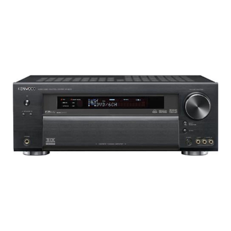
  9. Kenwood KR-V77R User manual

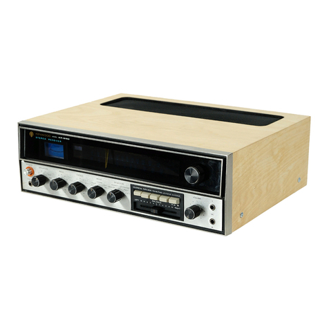
Kenwood KR-V77R User manual

Other Kenwood Stereo Receiver manuals

Kenwood KMDX92 User manual

Kenwood

Kenwood KMDX92 User manual

Kenwood VR-716 User manual

Kenwood

Kenwood VR-716 User manual

Kenwood KR-710 User manual

Kenwood

Kenwood KR-710 User manual

Kenwood KR-A5050 User manual

Kenwood

Kenwood KR-A5050 User manual

Kenwood KRF-X9060D User manual

Kenwood

Kenwood KRF-X9060D User manual

Kenwood KR-A5010 User manual

Kenwood

Kenwood KR-A5010 User manual

Kenwood 104AR User manual

Kenwood

Kenwood 104AR User manual

Kenwood 103AR User manual

Kenwood

Kenwood 103AR User manual

Kenwood KRF-V8080D User manual

Kenwood

Kenwood KRF-V8080D User manual

Kenwood KR-300HT User manual

Kenwood

Kenwood KR-300HT User manual

Kenwood KR-V5580 User manual

Kenwood

Kenwood KR-V5580 User manual

Kenwood VR Series User manual

Kenwood

Kenwood VR Series User manual

Kenwood VRS-N8100 - AV / Digital Multimedia Receiver User manual

Kenwood

Kenwood VRS-N8100 - AV / Digital Multimedia Receiver User manual

Kenwood 103AR User manual

Kenwood

Kenwood 103AR User manual

Kenwood KR-A4060 User manual

Kenwood

Kenwood KR-A4060 User manual

Kenwood VR-606 User manual

Kenwood

Kenwood VR-606 User manual

Kenwood KR-A4080 User manual

Kenwood

Kenwood KR-A4080 User manual

Kenwood KRF-V6070D User manual

Kenwood

Kenwood KRF-V6070D User manual

Kenwood VR-5900 Sovereign Safety guide

Kenwood

Kenwood VR-5900 Sovereign Safety guide

Kenwood Sovereign VR-5080 User manual

Kenwood

Kenwood Sovereign VR-5080 User manual

Kenwood KR-V8040 User manual

Kenwood

Kenwood KR-V8040 User manual

Kenwood KR-710 User manual

Kenwood

Kenwood KR-710 User manual

Kenwood KRF-V8090D User manual

Kenwood

Kenwood KRF-V8090D User manual

Kenwood KR-65 User manual

Kenwood

Kenwood KR-65 User manual

Popular Stereo Receiver manuals by other brands

Teac AG-680 Service manual

Teac

Teac AG-680 Service manual

Teac AGV1050 owner's manual

Teac

Teac AGV1050 owner's manual

Sony STR-435 operating instructions

Sony

Sony STR-435 operating instructions

Pioneer Elite SC-68 Service manual

Pioneer

Pioneer Elite SC-68 Service manual

Pioneer SX-1250 operating instructions

Pioneer

Pioneer SX-1250 operating instructions

Marantz CINEMA 70S owner's manual

Marantz

Marantz CINEMA 70S owner's manual

Yamaha RX-830 owner's manual

Yamaha

Yamaha RX-830 owner's manual

Pioneer AVH-Z7250BT owner's manual

Pioneer

Pioneer AVH-Z7250BT owner's manual

Denon AVR-1311 owner's manual

Denon

Denon AVR-1311 owner's manual

Denon AVR-S760H owner's manual

Denon

Denon AVR-S760H owner's manual

Denon AVR-X7200W Service manual

Denon

Denon AVR-X7200W Service manual

Sony XAV-1500 operating instructions

Sony

Sony XAV-1500 operating instructions

Radio Shack DX-399 owner's manual

Radio Shack

Radio Shack DX-399 owner's manual

Sony STR-DE535 - Fm Stereo/fm-am Receiver operating instructions

Sony

Sony STR-DE535 - Fm Stereo/fm-am Receiver operating instructions

Pioneer SX-1000TA operating instructions

Pioneer

Pioneer SX-1000TA operating instructions

Yamaha MusicCast TSR-5B3D owner's manual

Yamaha

Yamaha MusicCast TSR-5B3D owner's manual

Sony STR-DG500 - Multi Channel Av Receiver Service manual

Sony

Sony STR-DG500 - Multi Channel Av Receiver Service manual

Sherwood Newcastle RX-770 operating instructions

Sherwood

Sherwood Newcastle RX-770 operating instructions

manuals.online logo
manuals.online logoBrands
  • About & Mission
  • Contact us
  • Privacy Policy
  • Terms and Conditions

Copyright 2025 Manuals.Online. All Rights Reserved.

KR-\V/77
Rp
|
KE
\
WO
O
SERVICE
MANUAL
©1988-6
PRINTED
IN
JAPAN
B51-3569-00
(0)
1648
Slide
switch
(POWER)
Front
glass
Metallic
cabinet
Knob
ass‘y
(S40-1064-05)
(B10-0962-03)
(A01-1650-01)
(K29-3253-04)
Knob
(GE)
Panel
Knob
(SEL)
(K29-2994-03)
(A20-5535-02)
(K29-2995-03)
KENIWOOD
auon-vine|}
ovens
mucaiven
Knevern
REARS
AT
a
we
Phone
jack
(PHONES)
Knob
(GE)
Escutcheon
Knob
(SEL)
Remote
controller
ass'y*
(E11-0162-05)
(K29-2993-03)
(BO7-1815-04)
(K29-2996-03)
(A70-)
Knob
(SPEAKERS)
Foot
Knob
(MATRIX
SURROUND)
Dressing
plate
({K27-1304-04)x2
(JO2-01
70-04)
x4
(K29-2999-04)
‘
(BO3-2451-04)
Slide
switch*
Miniature
phone
jack
(SYSTEM)
AC
outlet*
($31-2072-05)
{E11-0165-05)
(E03-0086-05)
Screw
terminal
board
(2P)
ANT
Binding
post
Phono
jack
Lock
terminal
board
(8P)
SPEAKER
Slide
switch
(Power
type)
AC*
({E20-0318-05)
(NO8-01
28-35)
(E13-0487-05)
(£20-0823-05)
($31-2128-05)
Puxtaid
Phono
jack
(8P)
TAPE1,2
Lock
terminal
board
(SURROUND
SP)
AC
power
cord*
(E13-0820-05)
(€20-0475-05)
_
(E30-)
Phono
jack
(6P)
PHONO,CD,AUX
Phono
jack
(6P)
VIDEO1,2
Slide
switch
Power
cord
bushing
(E13-0621-05)
{E13-0621-05)
(IMPEDANCE
SELECTOR)
(J42-0083-05)
($31-2136-05)
*
Refer
to
parts
list
on
page
51.
KR-V77R
CONTENTS/CONTROLS
AND
INDICATORS
CONTENTS
|
CONTROLS
AND
INDICATORS
......--.--0-0005
2
DISASSEMBLY
FOR
REPAIR
..........-.-
vee
14
BLOCK
LEVEL
DIAGRAM
........--0+20+-055
15
CIRCUIT
DESCRIPTION
Description
of
componentS...---
ees
eee
eens
16
Microprocessor
:
uPD75108CW-170
or
-200
(X14-2320-11
2:
1C1)
22.
ee
ee
eee
eee
et
eee
18
ADJUSTMENT
1.2.2.0
-
0c
eee
eee
ee
eee
24
REGLAGE
......2
2
cee
eee
ee
tee
ete
25
CONTROLS
AND
INDICATORS
KENWOOD
ncio-woeo
stereo
arctien
xnvr7n
seeseseseaneneceresateneeserencey
parrsersecsstsnaneercal
vaio
Twice
Te]
ABGLEICH
..
1...
cee
ce
ee
ee
eee
eee
26
ADJUSTMENT/REGLAGE/ABGLEICH............
27
VOLTAGE
CHECK
TABLE
.......-.-0+2+2-0>-
28
PC
BOARD
(COMPONENT
SIDE
VIEW)
.......-..
29
PC
BOARD
(FOIL
SIDE
VIEW)
......22
0-000
eee
33
CIRCUIT
DIAGRAM
.....
cusgre
fata:
Sinvace.eSeite:
0
Waar
37
EXPLODED
VIEW
...
2...
cece
eet
ee
eee
49
PARTS
LIST
2.1.0...
eee
eee
et
ene
ene
nee
51
SPECIFICATIONS
........50-02005
BACK
COVER
Saar,
KR-V77R
@
POWER
switch
Press
this
switch
to
turn
on
power.
Press
it
again
to
turn
power
off.
@
SPEAKERS
A
and
B
switches
A,B
OFF
-
This
position
silences
all
speakers
to
permit
private
use
of
headphones.
A
ON
-
Activates
speakers
connected
to
the
SPEAKERS
A
terminals
on
the
rear
panel.
B
ON
-
Activates
speakers
connected
to
the
SPEAKERS
B
terminals
on
the
rear
panel.
A,B
ON
-
Activates
speakers
connected
to
the
SPEAK-
ERS
A
and
B
terminals
simultaneously.
Note:
——_—_____________-_____—-
When
the
SPEAKERS
A
and
B
switches
are
used
at
the
same
time,
the
speakers
connected
to
the
SPEAKERS
A
and
B
terminals
are
connected
in
series.
In
this
respect,
whenever
using
the
SPEAK-
ERS
A
and
B
switches
at
the
same
time,
be
sure
that
two
pairs
of
speakers
are
connected
to
the
terminals
A
and
B,
otherwise
no
sound
is
output.
©
PHONES
jack
Stereo
headphones
are
plugged
into
this
jack.
©
EQ
(Equalizer)
PRESET
keys
Use
these
keys
to
store
equalizer
curves
in
memory
or
to
‘recall
them.
PGM:
User-adjusted
equalizer
curves
can
be
programmed
as
desired
and
stored
in
memory:
up
to
five
patterns.
SET:
Five
factory-preset
equalizer
curves
are
stored
in
memory.
Up
to
10
equalizer curve
memories
are
available
in
total.
Press
the
PGM/SET
key
to
select
either
the
user-
programmed
pattern
or
the
factory-preset
pattern.
©
Equalizer
level
controls
Adjust
these
controls
up
and
down
to
equalize
the
sound
by
+12
dB
to
the
center
frequency
indicated.
@
Equalizer
function
keys
@
Equalizer
preset
mode
key
(PGM/SET)
Each
time
this
key
is
pressed,
the
recall
mode
of
the
equalizer
preset
curves
alternates
between
PGM
(user
programmed
patterns)
and
SET
(factory
preset
patterns).
CONTROLS
AND
INDICATORS
@
Equalizer
preset
MEMORY
key
This
key
is
used
to
store
an
equalizer
curve
into
the
PGM
PRESET
memories.
First,
select
the
desired
equalizer
curve
and
then
press
this
key.
Then
press
any
of
the
PRESET
(A
to
E)
keys.
The
selected
equalizer
curve
will
be
stored
in
the
memory
indicated
by
the
PRESET
key
pressed.
@
Equalizer
(EQ,
ON)
key
Press
this
switch
to
ON
and
the
frequency
characteristic
will
be
modified
by
passing
through
the
graphic
equalizer.
In
the
DEFEAT
position,
the
frequency
characteristic
remains
unchanged.
@
EQ
REC
key
Used
when
recording
the
source
onto
the
tape’
deck
through
the
equalized
response
of
the
graphic
equalizer.
@
System
memory
keys
@
SYSTEM
MEMORY
channel
key
(M-1/M-2)
Two
groups
of
memory
can
be
used
with
the
preset
channel
key
of
the
System
Memory
system.
After
entering
the
memory
preset
mode
by
pressing
the
SYSTEM
MEMO-
RY
key,
press
the
M-1
or
M-2
key.
@
System
MEMORY
key
This
key
is
used
to
store
the
currently
playing
condition
in
memory.
©
DOLBY
SURROUND
key
Press
this
key
to
activate
or
deactivate
the
surround
output.
In
the
KR-V77R,
MATRIX
surround
mode
is
automatically
entered
when
this
key
is
pressed.
With
the
KR-V77R,
when
the
speaker
selector
switch
at
the
rear
is
set
to
80.
OR
MORE,
the
surround
mode
cannot
be
obtained.
©
Input
selector
switches
TAPE
1-Press
this
switch
to
play
back
a
tape
deck
connected
to
the
TAPE
1
jacks.
TAPE
2/MONITOR
-
Press
this
switch
to
play
back
a
tape
deck
connected
to
the
TAPE
2
jacks.
(The
TAPE
2
switch
is
Operated
in
priority
to
any
other
audio
input
systems.)
VIDEO
1
-
Selects
the
video
recorders
connected
to
the
VIDEO
1
jacks.
:
VIDEO
2-Select
the
video
recorders
connected
to
the
VIDEO
2
jacks.
CD
-
Selects
the
source
connected
the
CD
jacks.
PHONO
-Selects
the
program
source
played
on
the
turntable.
TUNER
-
Selects
the
tuner
mode.
AUX
-
Selects
the
source
connected
the
AUX
jacks.
@
AUDIO
INJECTION
key
Press
this
key
ON
when
replacing
the
sound
of
VIDEO
2
with
that
of
AUDIO
source
is
required
on
dubbing
between
VIDEO
sources.
KR-V77F
@®
MUTING
key
When
the
muting
key
is
pressed,
the
MUTING
indicator
in
the
display
window
will.flash,
and
the
overall
listening
sound
level
is
reduced.
When
the
key
is
pressed
again.
you
can
restore
exactly
the
same
listening
level
as
before.
@
REMOTE
SENSOR
Point
the
supplied
remote
control
unit
towards
this
sensor
and
operate.
@®
REMOTE
POWER
STAND
BY
indicator
This
indicator
lights
so
far
as
the
power
cord
is
plugged
into
the
AC
outlet.
It
is
lit
to
show
that
the
POWER
switch
on
the
front
panel
or
the
POWER
key
on
the
remote
control
unit
can
be
activated.
@®
BALANCE
contro!
key
Governs
the
amount
of
sound
coming
from
each
paired
speakers
to
get
optimum
stereo
effect.
Pressing
the
RIGHT
key
will
decrease
the
left
channel
volume
and
pressing
the
LEFT
key
will
decrease
the
right
channel
volume.
When
the
BALANCE
controls
is
pressed,
display
window
shows
the
BALANCE
indicator.
@
MAIN
VOLUME
control
key
This
contro!
adjusts
the
left-
and
right-channel
volumes
simultaneously.
Set
it
for
the
desired
listening
level.
Pressing
the
up
(A)
side
increases
the
volume
and
pressing
the
down
(V)
side
decreases
it.
Indicator
(A)
or
(V)
blinks
when
this
unit
is
operated
directly
or
with
the
remote
control
unit.
The
volume
level
of
the
rear
speakers
are
controlled
at
the
same
time.
@
Band
selector
switches
FM
-
For
FM
broadcasts.
AWMi
-
For
AM
broadcasts.
@®
Numeric
(1
~
0/10)
keys
Use
these
keys
to:
1)
input
directly
the
digits
of
frequencies,
or
2)
store
and
recall
frequencies
in
the
preset
channel.
@
Tunning
function
keys
@
DIGIT
key
In
the
station
name
input
mode,
pressing
this
key
advances
the
column
after
selecting
the
character
with
the
Tuning
UP/DOWN
key.
When
this
operation
is
repeated
four
time,
the
station
name
input
mode
will
be
released
automatically.
@
CHARACTER
key
Press
this
key
to
activate
the
station
name
input
mode.
KR-V77R
CONTROLS
AND
INDICATORS
@
PRESET
SCAN
key
Use
this
key
for
preset
channel
scanning.
When
a
frequency
stored
in
the
preset
memory
is
being
received,
pressing
this
key
shifts
the
reception
to
the
next
frequency
stored
in
the
preset
memory.
(The
preset
channels
are
scanned
in
the
order
1,
2......
11,12...
20,)
To
stop
a
scanning
operation,
press
the
SCAN
key
again.
@
MEMORY
key
When
the
input
mode
is
TUNER,
use
this
key
to
store
new
broadcast
station
data
in
the
preset
channel
memory.
By
pressing
the
MEMORY
key,
setting
the
preset
channel
to
1-10
or
11-20
and
by
pressing
one
of
the
numeric
keys,
the
frequency
being
received
is
stored
in
the
memory
in
the
numeric
key
pressed.
@
DIRECT
key
Used
to
tune
to
the
station
directly.
Input
the
desired
frequency
numerics
with
the
numeric
keys
after
pressing
the
DIRECT
key.
@
Preset
function
(1-10/11-20)
key
Used
to
select
1-10
or
11-20
setting
for
the
preset
channel.
In
either
FM
or
AM
mode,
20
stations
can
be
preset
as
random
as
each
setting
(1-10"
or
11-20")
can
contain
10
preset
stations.
indicator
“1-10”
lights
when
“1-10”
setting
is
used,
and
indicator
“11-20”
lights
when
“41-20”
setting
is
used.
@
AUTO/MANUAL
(MONO)
key
When
this
key
is
pressed,
the
AUTO
indicator
will
light.
The
frequency
will
automatically
stop
at
a
station
in
automatic
tuning
mode.
When
a
stereo
broadcast
is
received,
the
output
sound
is
automatically
changed
to
stereo.
@
TUNING
keys
Used
to
change
the
frequency.
Pressing
UP
side
will
advance
to
the
higher
frequency
and
pressing
DOWN
side
to
the
lower
frequency.
In
the
station
name
input
mode,
this
key
is
used
to
select
the
character.
@®
Display
window
HRETEEEELEEE
EETETEEEEEEEE
HEEEEETEEEE
rr
8
*
8
z
@
In
graphic
equalizer
mode,
displays
the
equalizer
level
display,
the
music
spectrum
analyzer
display
and
peak
hold
display.
@
Displays
when
storing
or
recalling
equalizer
preset
channel
in
memory.
@®
Lights
when
the
Memory
(EQ)
key
is
pressed
to
store
the
desired
equalizer
curve.
(@
Lights
when
the
TAPE-2
key
is
pressed.
@
VIDEO
monitor
out
indicator.
©
Lights
when
the
AUDIO
INJECTION
key
is
pressed.
@
This
displays
the
input
mode,
preset
channel,
station
name,
front
volume
level,
rear
level,
balance,
DOLBY
surround
(KR-V87R),
EQ
preset
channel,
SPI
level
(KR-V87R),
system
memory
indicator.
“1-10"or
“11-20”
lights
according
to
the
selection
of
the
preset
function
keys.
@)
Front
volume
level
indicator
This
indicator
displays
the
volume
level
for
the
front-
channel
speakers.
,
zp
in
>
»
VOLUME
LEVEL
@®
Rear
volume
level
indicator
(KR-V87R)
The
volume
level
of
the
rear-channel
speakers
is
indicat-
ed
within
a
+
20
dB
range.
@
Flashes
when
the
MUTING
key
is
pressed.
@
Displays
the
digital
frequency
display.
@
Displays
the
tuner
band
“FM”
or
“AM”
In
tuner
mode,
lights
when
a
stereo
broadcast
is
tuned
in.
@
In
tuner
mode,
lights
when
a
station
is
tuned
in.
Lights
during
auto
tuning.
@
Lights
when
the
MEMORY
key
is
pressed.
@
This
indicator
lights
when
EQ
REC
(equalizer
recording)
key
is
pressed.
Lights
when
the
Equalizer
(EQ.
ON)
key
is
set
to
“ON”.
Lights
when
the
Equalizer
(EQ..
ON)
key
is
set
to
“DEFEAT”.
@
Lights
when
the
Equalizer
preset
mode
(PGM/SET)
key
is
set
to
“PGM”.
‘@
Lights
when
the
Equalizer
preset
mode
(PGM/SET)
key
is
set
to
“SET”.
CONTROLS
AND
INDICATORS
@
Listening
to
AM/FM
1.
Press
the
Power
switch
to
ON.
2.
Press
the
TUNER
key
of
the
input
selector.
3.
Select
FM
or
AM
of
the
band
(FM/AM)
selector.
4.
Tune
to
the
required
station
with
following
proce-
dures:
Auto
tuning,
Manual
tuning
or
Direct
tuning.
Auto
tuning
1.
Press
the
AUTO/MANUAL
(MONO)
key
to
set
to
“AUTO”.
2.
Press
the
UP
or
DOWN
TUNING
key:
The
frequency
will
automatically
increase
or
decrease
until
a
station
with
sufficient
signal
level
is
received.
To
stop
the
frequency
scanning
before
a
station
is
received,
press
the
AUTO/MANUAL
key
to
set
to
“MANUAL”.
3.
Adjust
the
VOLUME
control
to
the
required
listening
level
and
use
the
graphic
equalizer
control
to
adjust
the
sound
to
your
own
preference.
Manual
tuning
1.
Press
the
AUTO/MANUAL
(MONO)
key
to
set
to
“MANUAL”.
2.
Press
the
UP/DOWN
TUNING
key
to
tune
in
the
desired
Station.
To
continuously
increase
or
decrease
frequencies,
hold
the
TUNNING
key
depressed.
3.
Adjust
the
VOLUME
control
to
the
required
listening
level
and
use
the
graphic
equalizer
control
to
adjust
the
sound
to
your
own
preference.
Direct
tuning
1.
Select
FM
or
AM
with
the
FM,
AM
selector
switch.
2.
Press
the
DIRECT
key.
3.
Input
the
desired
frequency
with
numeric
keys.
4,
The
receiver
enters
the
radio
reception
mode
just
after
the
frequency
value
has
been
input.
(If
the
input
value
is
outside
the
tuning
range,
the
frequency
display
flashes
for
5
seconds
and
the
receiver
returns
to
the
radio
reception
mode
of
the
last
channel.)
@
Presetting
broadcast
station
data
In
total
up
to
20
stations
data
(station
frequency
and
station
name)
can
be
stored
in
memory.
1.
Select
the
desired
station
with
either
AUTO
tuning,
MANUAL
tuning
or
DIRECT
tuning.
2.
Input
the
broadcast
station
name
in
accordance
with
the
character
input
procedure.
For
the
broadcast
station
names,
up
to
4
characters
can
be
input.
@
When
the
contents
in
item
2
is
not
required
for
display
memory.
proceed
to
item
3
after
item
1.
3.
Press
the
preset
function
key
to
select
1-10"
or
“14-20”.
4.
Press
the
MEMORY
key.
(The
MEMORY
indicator
lights.)
5.
Press
one
of
the
numeric
keys:
The
frequency
being
tuned
in
and
the
station
name
are
stored.
Character
input
procedure
1.
Press
the
CHARACTER
button
to
set
the
character
input
mode.
The
first
column
of
the
character
display
section
begins
flashing.
2.
Press
the
TUNING
UP/DOWN
key
to
select
the
character.
3.
When
the
desired
character
is
displayed,
press
the
DIGIT
key.
Flashing
will
shift
to
the
next
column.
4.
Repeat
procedure
3
and
4
for
four
times
to
complete
inputting.
The
character
input
mode
will
be
released.
@
Even
in
the
middle
of
inputting.
pressing
the
CHARAC-
TER
key
again
will
release
the
character
input
mode.
At
this
time,
the
data
which
has
been
input
is
valid.
Example
1:
To
preset
the
91.50
MHz
FM
broadcast
and
a
station
name
“W
N
Y”
when
the
station
other
than
the
preset
channel
memories
is
received.
1.
Tune
to
91.50
MHz
FM
broadcast.
wo
CREEP
G
iS
Cae
Lp
|
(PRES
ee
3
eee
2.
Press
the
CHARACTER
key.
3.
Press
the
TUNING
UP
key
twenty-three
time
to
select
Wy"
__A->B-C-~D-E-F~G?-H-|l>
J
>
KLM
o>
NO
KR-V77R
CONTROLS
AND
INDICATORS
4.
Press
the
DIGIT
key.
5.
TUNING
UP
key
fourteen
times
to
select
“N”.
_A>B>C>D>E>F>G>H>1>J>K>L>MPN
6.
Press
the
DIGIT
key.
7.
TUNING
UP
key
twenty-five
times
to
select
“Y”.
_A>B-C-D—-E>F>G--H>1>J+K>L>M>N>
O-P>0>R>S?T-U-V>W>xXY
8.
As
the
fourth
column
should
be
left
blank,
press
the
DIGIT
key
twice
or
press
the
CHARACTER
key.
ao
CES
re
Af
INT
dd
WN
Example
2:
To
change
the
station
name
from
“WHY
8'"
for
810
kHz
AM
broadcast
memorized
in
12
preset
channel
to
“W,
GY":
1.
Recall
the
12
preset
channel
with
the
PRESET
1-
10/11-20-switch
and
the
PRESET-key
according
to
“Recalling
the
Preset
Memory”.
eS
BAG
WHY
Ios
2.
Press
the
CHARACTER
key.
me
si
WKH
YA
fos
3.
Press
the
DIGIT
key
to
shift
the
flashing
character
to
the
next
column
since
the
first
character
““W”
should
be
left
as
it
is.
H>G
5.
Press
DIGIT
key
twice.
6.
Press
the
TUNING
key
to
select
a
blank.
{f-
wv
Wa
Voie
7.
Press
the
DIGIT
key
or
press
the
CHARACTER
key.
WN
=
CONTROLS
AND
INDICATORS
Listening
to
a
preset
station
.
Press
the
preset
function
key
to
select
“1-10”
or
“11-20”.
.
Press
a
numeric
key
under
which
memory
has
been
preset.
.
Adjust
the
VOLUME
control
to
the
required
listening
level
and
use
the
graphic
equalizer
control
to
adjust
the
sound
to
your
own
preference.
Listening
to
record
playing
.
Press
the
PHONO
key
of
the
INPUT
SELECTOR
switches.
.
Operate
the
turntable
to
play
back
a
record.
.
Adjust
the
VOLUME
control
to
the
required
listening
fevel
and
use
the
graphic
equalizer
control
to
adjust
the
sound
to
your
own
preference.
With
a
turntable
that
is
connected
to
this
unit
with
a
System
Control
cord,
the
convenient
System
Control
operations
are
available.
For
details
on
this,
refer
to
“System
Control
Operation’
on
page
20.
Listening
to
the
program
source
connected
to
the
CD
or
AUX
jacks
.
Press
the
CD
or
AUX
key
of
the
input
selector
switches.
.
Operate
the
component
connected
to
the
CD
or
AUX
jacks.
.
Adjust
the
VOLUME
control
to
the
required
listening
level
and
use
the
graphic
equalizer
controls
to
adjust
the
sound
to
your
own
preference.
With
a
CD-player
that
is
connected
to
this
unit
with
a-
System
Control
cord,
the
convenient
System
Contro
operations
are
available.
For
details
on
this,
refer
to
“System
Control
Operation’
on
page
20.
@
Tape
deck
operation
1.
Press
the
appropriate
TAPE
key
of
the
input
selector
switches
(1
or
2)
to
select
output
from
a
tape
deck
connected
to
the
TAPE
1
or
2
jacks.
2.
Operate
the
tape
deck.
3.
Adjust
the
VOLUME
control
to
the
required
listening
level
and
use
the
graphic
equalizer
controls
to
adjust
the
sound
to
your
own
preference.
@
With
a
tape
deck
(connected
to
the
TAPE
1
jacks)
that
is
connected
to
this
unit
with
a
System
Control
cord.
the
convenient
System
Control
operations
are
available.
For
details
on
this,
refer
to
“System
Control
Operation”
on
page
20.
Note:
——_—__————
When
both
key
(TAPE-1
and
TAPE-2)
are
pressed,
TAPE-2
setting
has
priority.
Recording
1.
Press
the
appropriate
key
of
the
INPUT.
SELECTOR
switches.
‘2.
Set
up
your
tape
deck(s)
for
recording
and
set
the
recording
level
with
the
controls
on
your
tape
deck(s).
3.
Adjust
listening
level
at
the
unit
to
suit
your
listening
preference.
Note:
———________
eee
When
a
tape
deck
is
connected
to
this
unit
with
a
System
Control
cord,
all
of
the
input
selector
switches
are
disabled
during
recording
and
do
not
function
until
recording
is
finished.
This
will
prevent
the
recording
from
being
interrupted.
Tape
dubbing
Tape
recordings
may
be
duplicated
(dubbed)
easily
using
two
tape
decks
connected
to
the
TAPE
1
and
2
jacks.
For
example:
(TAPE
1
to
2):
1.
Connect
two
tape
decks
to
the
TAPE
71
and
TAPE
2
jacks
2.
Press
the
TAPE
1
switch.
3.
Play
back
the
recorded
tape
and
adjust
the
recording
levels
before
starting
tape
dubbing.
(TAPE
2
to
1):
1.
Press
the
TAPE
2
switch.
2.
Press
a
key
except
TAPE
1
of
the
INPUT
SELECTOR
switches
such
as
AUX.
3.
Play
back
the
recorded
tape
and
adjust
the
eorcing
levels
before
starting
tape
dubbing.
4.
Do
not
press
the
TAPE
1
switch
during
eerding
with
tape
deck
1.
Note:
———_———__——?SS
Adjust
record
levels
on
the
deck
that
is
making
the
eapy
using
that
deck’s
operating
controls.
KR-V77R
CONTROLS
AND
INDICATORS
@
VIDEO
deck
operation
Listening
to
video
recorder
audio
sound
1.
Press
the
appropriate
VIDEO
(1,
2)
key
of
the
INPUT
SELECTOR
to
select
output
from
a
video
recorder
connected
to
the
VIDEO
(1,
2)
jacks.
2.
Operate
the
video
recorder.
:
3.
Adjust
the
VOLUME
controls
for
your
preference.
4.
When
4
video
monitor
is
connected
to
the
VIDEO
MONITOR
OUT
jack
on
the
rear
panel,
the
picture
from
the
recorder
can
also
be
monitored.
Dubbing
between
two
VCRs
Video
dubbing
can
be
performed
while
listening
to
any
desired
source.
With
this
set,
through
dubbing
from
to
is
possible.
To
operate,
set
the
video
deck
to
record-pause
mode
and
set
the
video
deck
to
playback
mode.
At
the
same
time
as
the
video
deck
starts
to
play,
the
record-pause
mode
of
the
video
deck
is
released
and
recording
starts.
Audio
injection
During
video
dubbing.
the
sound
from
the
VCR
can
be
replaced
with
the
desired
audio
source
without
affecting
the
picture.
At
this.
graphic
equalizer
can
be
applied
to
the
recording
'
audio
source.
1.
Press
the
AUDIO
INJECTION
switch
so
that
the
‘“AU-
DIO
INJECTION”
display
is
illuminated.
2.
Select
the
desired
audio
source
for
Audio
injection
with
the
INPUT
SELECTOR.
3.
When
equalizer
compensation
is
required
when
record-
ing
a
desired
audio
source
with
audio
injection
ON,
press
the
EQ.REC
key.
The
indicator
fights
up.
Set
the
equalizer
controls
as
desired.
.
Operate
each
VCR
for
dubbing.
-$@@e
AUDIO
INJECTION
display
Audio
source
used
for
Audio
injection
(when
TAPE
2
is
selected,
the
TAPE
2
source
is
prior
to
another.)
@
Graphic
equalizer
operation
Normal
operation
1.
Select
the
desired
source.
2.
Press
the
equalizer
(EQ.
ON)
key
to
ON.
@
The
ON
indicator
lights
up
in
the
display
window.
3.
Press
the
equalizer
level
control
UP
DOWN
keys
so
that
the
equalized
sound
is
heard
from
the
speakers
as
desired.
Preset
procedure
Use
EQ
PRESET
key
to
store
equalizer
curves
in
memory
or
to
recall
them.
(Five
different
equalizer
curves
can
be
stored.)
.
Select
the
desired
source.
.
Press
the
equalizer
(EQ.
ON)
key
to
ON.
.
Set
the
your
desired
equalizer
curve.
.
Press
the
MEMORY
(EQ)
key.
.
Press
the
desired
EQ
PRESET
keys
(M-A
~~
M-E)
to
store
the
equalizer
curve.
ahon-—
‘Preset
operation
The
preset
memory
of
this
unit
is
available
in
two
types
the
“PGM”
memory
in
which
the
user-created
desired
sound
response
can
be
preset,
and
the
“SET”
memory
in
which
the
factory-preset
sound
equalizer
curves
are
prepared.
Use
them
by
referring
to
‘Characteristics
of
the
SET
preset
memories”.
1.
Select
SET
or
PGM.
@
The
previously
selected
equalizer
curve
of
the
preset
channel
is
displayed.
2.
Select
preset
key
Characteristics
of
the
“SET”
preset
memories
A:
For
solid
and
punchy
sound.
B:
For
effective
reproduction
of
the
dynamic
movie
sound.
C:
For
easy
to
listen
background
music.
:
For
musical
sound
reproduction
in
a
sense
of
lively
For
reproducing
the
vocal
music
realistically.
EQ
REC
switch
Press
this
switch,
signals
will
allow
equalized
to.
be
recorded
on
TAPE
1.
If
you
wish
to
record
non-equalized
signals
with
the
equalizer
switch
in
the
ON
position,
turn
the
equalizer
recording
switch
to
OFF.
This
will
allow
you
to
hear
the
equalized
signals
while
recording
non-equalized
signals.
Note:
The
equalized
signal
is
not
output
at
TAPE
2
REC
jacks.
KR-V77F
CONTROLS
AND
INDICATORS
-
@
Surround
operation
.
MATRIX
SURROUND
Caution:
Before
starting
operation,
be.sure
to
check
the
following
poings:
1.
The
SPEAKER
IMPEDANCE
SELECTOR
on
the
rear
panel
of
this
unit
is
set
to
the
“LESS
THAN
80”
position.
2.
Each
of
the
front-channel
and
rear-channel
speaker
systems
has
an
impedance
of
more
than
80.
1.
Set
the
SURROUND
key
to
ON.
@
The
MATRIX
SURROUND
indication
which
is
marked
on
the
key
lights.
o——
SURROUND
——————
MATRIX
SURROUND
2.
Select
the
source
which
is
desired
to
be
expected
for
surround
sound
effect,
and
play
it.
3.
Adjust
the
volume
control
and
balance
between
the
front
speakers
and
the
rear
speakers
by
controlling
the
MAIN
VOLUME
control
key.
Note:
——_———__——
1.
When
the
SPEAKER
IMPEDANCE
SELECTOR
on
the
rear
panel
is
set
to
the
“MORE
THAN
82”
position,
the
SUR-
ROUND
key
does
not
function.
;
2.
If
speakers
having
an
impedance
of
less
than
8
ohms
are
connected,
overheating
may
occur
and
cause
trouble
to
this
unit.
KR-V77R
10
m
System
Memory
The
required
playback
condition
can
be
stored
in
memory
for
each
music
program
(tape,
compact
disc,
phonograph
record
(disc)
or
broadcasting
program),
so that
the
same
volume
level,
the
same
balance
(between
front
and
rear
channels),
and
the
same
equalizer
pattern,
etc.
can
be
recalled
at
any
time
instantly.
Two
types
of
settings
can
be
stored
in
memory,
and
by
pressing
the
SYSTEM
MEMORY
(M-1
or
M-2)
key
you
can
recall
the
preset
sound
field
condition
instantly.
Stored
contents:
The
stored
contents
in
the
System
Memory
are
as
follows:
©
input
selector
(CD,
PHONO,
TUNER,
TAPE,
VIDEO.
etc.)
Preset
channel
in
the
TUNER
position
Audio
injection
EQ.
key
setting
(ON/DEFEAT)
EQ.
REC
key
setting
(ON/OFF)
Preset
channel
of
the
equalizer
pattern
SURROUND
setting
(ON/OFF)
Front-channel
volume
level
Front-channel
balance
control
setting
OO000000
How
to
preset
the
System
Memory:
1.
Set
the
playback
conditions
as
required.
@
When
selecting
the
tuner
or
equalizer,
be
sure
to
designate
the
preset
channel.
.
Press
the
SYSTEM
MEMORY
key.
2
'
@
The
display
shows
“SYS
M-”
for
about
5
seconds.
@
When
“SYS
M”
is
blinking
in
the
display,
the
tuner
or
equalizer
pattern
is
not
preset
in
memory.
After
presetting
the
playback
condition
for
each
chan-
nel,
press
the
MEMORY
key
again.
How
to
recall
System
Memory:
1.
Press
the
M-1
or
M-2
key.
@
The
display
shows
“SYS
M-1”
or
“SYS
M-2”
for
about
1
second,
and
the
settings
of
each
section
are
changed
to
the
preset
contents.
Readjust
the
setting
of
each
section
as
required.
@
When
PHONO
is
selected
for
the
input
selector.
with
a
system-controlled
turntable
connected,
the
turntable
will
automatically
start
playing
by
recalling
the
System
Memory.
Therefore,
be
sure
to
set
the
record
on
the
platter
of
the
turntable
before
activating
the
System
Memory
function.
@
In
the
same
way,
when
a
system-ccntrolled
tape
deck
or
CD
player
is
connected
to
this
unit,
the
tape
deck
or
CD
player
can
be
started
automatically
by
activating
this
System
Memory
function.
S
Note:
-
1.
Do
not
set
the
volume
controls
to
an
excessively
high
volume
level..It
may
not
only
astonish
the
listener,
but
it
may
also
damage
the
speaker
or
amplifier.
;
2.
If
the
contents
of
the
preset.
channel
is
changed
after
designating
the
tuner
or
equalizer
section
channel
for
System
Memory,
the
contents
of
the
System
Memory
channel
will
also
be
changed.
CONTROLS
AND
INDICATORS
@
System
control
operation
Connection
Using
the
system
control
cord
provided
with
the
system
component
models
as
below,
make
connections
as
shown
on
page
7.
The
foiiowing
modeis
are
avaiiabie
for
the
system
control
operations.
Turntable:
KD-77F,
KD-67F
or
KD-47F
Cassette
deck:
KX-97CW,
KX-77CW
KX-67W
or
KX-87CR
DP-87,
DP-57,
DP-47,
DP-M107R,
DP-M97
or
DP-M97R
CD
player:
Note:
———___--_____----—>__—_———
Some
models
provide
two
or
three
system
control
jacks.
However,
when
used
with
this
receiver,
be
sure
to
connect
the
system
control
cord
to
the
jack
having
a
indication
of
@.
Operation
1.
Automatic
play
operation
When
starting
play
with
the
turntable,
cassette
deck
or
CD
player
connected
to
the
receiver,
press
the
desired
INPUT
SELECTOR
switch
on
the
receiver.
The
turnta-
ble,
cassette
deck
or
CD
player
will
automatically
enter
the
play
mode.
In
the
same
way,
pressing
the
Play
key
of
the
turntable,
cassette
deck
or
CD
player
will
automatically
switch
the
INPUT
SELECTOR
on
the
receiver
to
the
equipment
on
which
the
Play
key
is
pressed.
2.
Synchro
recording
To
record
the
sound
from
the
turntable
or
CD
player
onto
the
tape
with
the
cassette
deck,
press
the
PLAY
(START)
key
of
the
turntable
or
CD
player.
The
cassette
deck
will
start
recording
automatically.
synchronized
with
the
turntable
or
CD
player
starting
play.
For
more
details,
refer
to
the
instruction
manual
of
the
cassette
deck.
3.
Remote
control
When
the
remote
control
unit
provided
with
this
unit,
to
which
the
turntable,
cassette
deck
or
CD
PLAYER
is
connected,
is
equipped
with
related
control
keys,
the
related
components
can
be
controlled
using
these
keys.
Note:
During
recording
with
the
cassette
deck,
the
INPUT
SELECT
on
the
receiver
is
fixed
at
the
source
from
which
the
recording
is
made,
by
the
system
control
circuit.
At
this
time.
pressing
any
of
the
INPUT
SELECTOR
keys
does
no
function
even
when
it
is
pressed.