~
KR-A5010
CONTENTS/LISTENING
TO
BROADCASTS
CONTENTS
LISTENING
TO
BROADCASTS
...........:ccssssesscsessenees
2
6.
CX7925B
:
PLL
(X14-253X-XX
|
1C2)
........
cess
19
REMOTE
CONTROL...........:ccsccssscesesccecssersseeessssenseees
4
ADJUTIMENT
vissesscccscsccccassscarcocsciisiestsevsssvanecauronsess
20
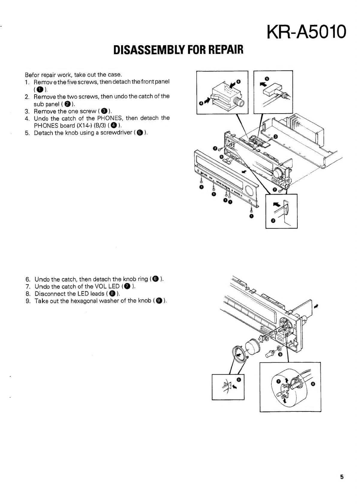
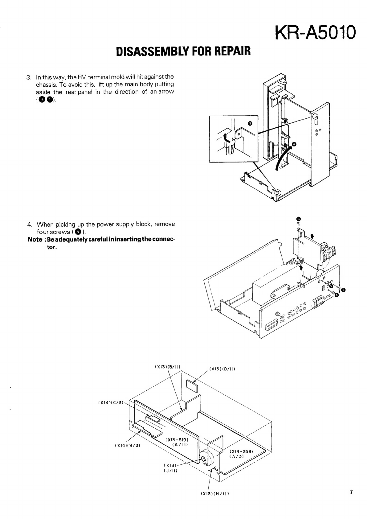
DISASSEMBLY
FOR
REPAIR
...........-::::sssssessesseeeeees
5
REGLAGE
sss
ccsisccsscsscstesesiescvsticapcatetzvasenivedeSeccasasuvsse
21
BLOCK
DIAGRAM
............:cccssesesccsecensorseeenerenenseseneees
8
ABGLEICH
eos.
ccicciseisacccsesscteseedeethcesaidttdiveisccees
22
CIRCUIT
DESCRIPTION
ADJUTMENT/REGLAGE/ABGLEICH
.................5
23
1.
Description
of
components
...........::csssessssseeens
8
VOLTAGE
TABLE
..........ccscsscsesssscenseesecesseenenenseseoes
24
2.
CXP5016-330S
PC
BOARD
(COMPONENT
SIDE
VIEW)
...........+++
25
Microprocessor
(X13-619X-XX
:
ICS)
............0..
10
PC
BOARD
(FOIL
SIDE
VIEW)
...........csseseccesceeneers
29
3.
STK4201/2
:
Main
amplifier
SCHEMATIC
DIAGRAM
.........ccscsssessccersseesseetsornsnees
33
(X14-253X-XX
:
1C7)
:
K,
P,
U,
UE,
M,
X
type
...17
SCHEMATIC
DIAGRAM
...........ceccscsessssereseseeeseees
37
4.
STK4201/5
Main
amplifier
EXPLODED
VIEW............:-..cccssscsssssseseesssseseeeeseenenees
41
(X14-2532-71
:
1C7)
:
E
type
.......ceesccsecsssceeeeeeees
17
PARTS:
UIST
ii.cccsecs
teas
snsctes
tices
wsteceuai
saveeatigs
sceassennnen
42
5,
AN7470
:
FM
MPX
(X14-253X-XX
:
1C3)...........
18
SPECIFICATIONS
............:scssesssesesesens
BACK
COVER
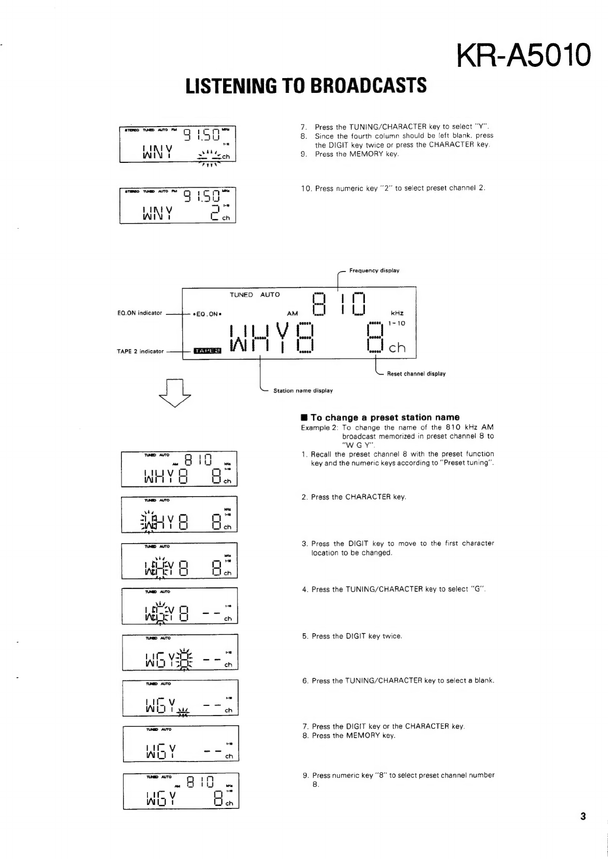
LISTENING
TO
BROADCASTS
This
unit
allows
both
the
frequencies
and
the
names
of
broadcasting
stations
to
be
preset.
When
a
station
is
recalled
by
preset
tuning,
the
display
shows
both
the
frequency
and
the
name
of
the
station.
(S.N.P.S.)
Preset
function
{1
-
10/11
-
20)
key
Numeric
(1~0/10)
keys
DIGIT
key
MEMORY
key
CHARACTER
key
TUNING/CHARACTER
keys
:
£
displ
h
ith
th
@
To
preset
station
names
and
frequencies
TUNING/CHARACTER
key
bie
.
(The
station
names
can
be
displayed
only
with
station
preset
in
CH
1
to
CH
10.)
Every
time
the
UP
segment
of
the
TUNING/CHARACTER
key
is
Example
1:
To
preset
the
91.50
MHz
FM
broadcast
pressed,
the
displayed
character
is
varied
in
the
following
order:
frequency
and
its
station
name
“WNY"
in
AB
Oo
Ze
Oe
1
2
Brees
9
preset
chane!
number
2.
Blank
(Pressing
the
DOWN
segment
varies
the
displayed
character
in
the
reverse
order.}
1.
Tune
to
91.50
MHz
FM.
2.
Press
the
CHARACTER
key.
Press
the
TUNING/CHARACTER
key
to
select
“W".
Press
the
DIGIT
key
to
set
the
character
and
move
to
the
next
location.
paula
Press
the
TUNING/CHARACTER
key
to
select
“N”.
Press
the
DIGIT
key.
STEREO
TUNED
AUTO
FM
oo
2
IN
Nite
Sch
aateomee