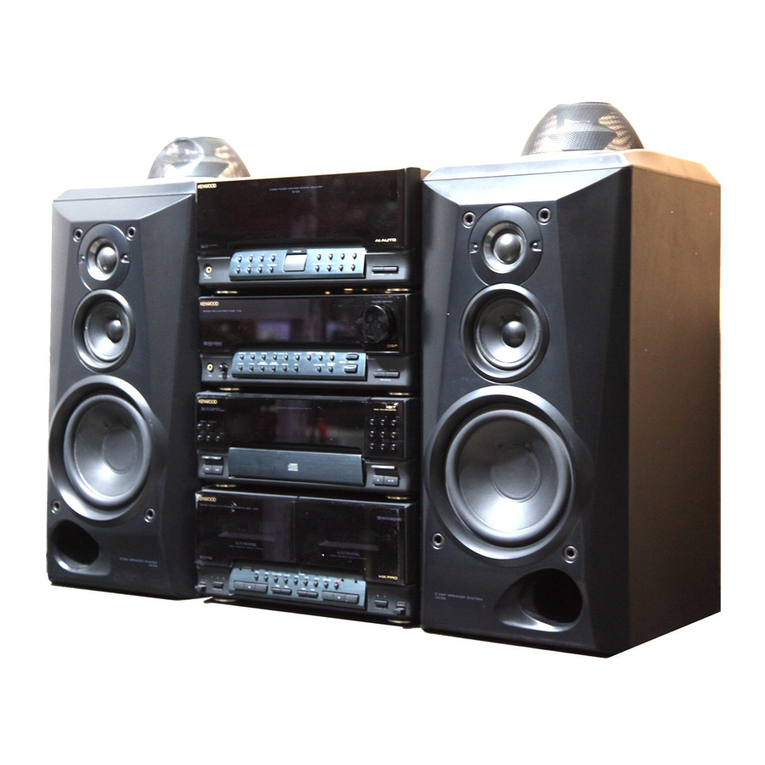
Kenwood K-821DV User manual

K-821DV
COMPACT HI-FI COMPONENT SYSTEM
INSTRUCTION MANUAL
© B60-5815-08/01 (E, X, K) GVT0295-001B
D
ecl
a
Declaration of Conformity with regard to
the EMC Directive 2004/108/EC
Manufacturer:
Kenwood Corporation
2967-3 Ishikawa-machi, Hachioji-shi, Tokyo, 192-8525 Japan
EU Representative’s:
Kenwood Electronics Europe BV
Amsterdamseweg 37, 1422 AC UITHOORN, The Netherlands
Europe only
TM
B60-5815-0801GVT0295-001BK-821DVEn.indb1B60-5815-0801GVT0295-001BK-821DVEn.indb1 10.1.254:56:28PM10.1.254:56:28PM

2
K-821DV
Safety precautions
WARNING :TOPREVENT FIRE OR ELECTRIC SHOCK, DONOT EXPOSE
THIS APPLIANCE TORAIN OR MOISTURE.
CAUTION
RISK OF ELECTRIC SHOCK
DO NOT OPEN
CAUTION: TOREDUCE THE RISKOF ELECTRIC SHOCK, DONOT REMOVE COVER
(OR BACK). NO USER-SERVICEABLEPARTS INSIDE. REFER SERVICING TO
QUALIFIED SERVICE PERSONNEL.
THE LIGHTNING FLASHWITHARROWHEAD SYMBOL, WITHIN ANEQUILATERAL TRIANGLE,
IS INTENDED TOALERT THE USER TOTHE PRESENCE OF UNINSULATED “DANGEROUS
VOLTAGE” WITHIN THE PRODUCT’S ENCLOSURE THAT MAY BE OF SUFFICIENT MAGNITUDETO
CONSTITUTEA RISKOF ELECTRIC SHOCK TOPERSONS.
THE EXCLAMATION POINT WITHIN ANEQUILATERAL TRIANGLEIS INTENDED TOALERT
THE USER TOTHE PRESENCE OF IMPORTANT OPERATING AND MAINTENANCE (SERVICING)
INSTRUCTIONS IN THE LITERATURE ACCOMPANYING THE APPLIANCE.
The marking of products using lasers
The marking this product has been classifi ed as Class 1. It means that
there is no danger of hazardous radiation outside the product.
Location: Back panel
CLASS 1
LASER PRODUCT
Safety Precautions
Before Applying Power
Caution: Read this page carefully to ensure safe operation.
Units are designed for operation as follows.
Australia .....................................................AC 240 V only
Europe ........................................................AC 230 V only
U.S.A. ...........................................................AC 120 V only
Except for U.S.A.
B60-5815-0801GVT0295-001BK-821DVEn.indb2B60-5815-0801GVT0295-001BK-821DVEn.indb2 10.1.254:56:28PM10.1.254:56:28PM

3
English
Safety Precautions
5. Ventilation
– Slots and openings in the cabinet are provided
for ventilation and to ensure reliable operation of
the product and to protect it from overheating.
Donot block any ventilation openings. Install in
accordance with the manufacturer’sinstructions.
The openings should never beblocked byplacing
the product on abed, sofa, rug, or other similar
surface. This product should not beplaced in a
built-in installation such as abookcase or rack
unless proper ventilation is provided or the
manufacturer’sinstructions havebeen adhered to.
6. Power Sources
– This product should beoperated only from the
type of power source indicated on the product. If
you are not sure of the type of power supply to
your home, consult your product dealer or local
power company.
7. CAUTION –Polarization
– Donot defeat the safety purpose of the polarized
or grounding-type plug. A polarized plug has two
blades with one wider than the other. A grounding
type plug has two blades and athird grounding
prong. The wide blade or the third prong are
provided for your safety. If the provided plug does
not fi tinto your outlet, consult an electrician for
replacement of the obsolete outlet.
8. Power Cord Protection
– Protect the power cord from being walked on
or pinched particularly at plugs, convenience
receptacles, and the point where they exit from
the apparatus.
IMPORTANT SAFETY INSTRUCTIONS
Caution: Read this page carefully to ensure safe operation.
Read These Instructions
– All the safety and operating instructions should
beread before the product is operated.
Keep These Instructions
– The safety and operating instructions should be
retained for future reference.
Heed All Warnings
– All warnings on the product and in the operating
instructions should beadhered to.
Follow All Instructions
– All operating and use instructions should be
followed.
1. Clean only with dry cloth
– Unplug this product from the wall outlet before
cleaning. Donot use liquid cleaners or aerosol
cleaners. Use adamp cloth for cleaning.
2. Attachments
– Only use attachments/accessories specifi ed by
the manufacturer.
3. Do not use this apparatus near water
– This product shall not beexposed to dripping
and splashing – for example, near abath tub,
wash bowl, kitchen sink, or laundry tub; in awet
basement; or near aswimming pool; and the like.
Donot place an object containing liquid, such as a
fl ower vase, on the appliance.
4. Accessories
– Use only with the cart, stand, tripod, bracket, or
table specifi ed bythe manufacturer, or sold with
the apparatus. When acart is used, use caution
when moving the cart/apparatus combination to
avoid injury from tip-over.
Continued to next page
B60-5815-0801GVT0295-001BK-821DVEn.indb3B60-5815-0801GVT0295-001BK-821DVEn.indb3 10.1.254:56:29PM10.1.254:56:29PM

Safety Precautions
4
K-821DV
9. Lightning
– Unplug this apparatus during lightning storms or
when unused for long periods of time.
10. Overloading
– Donot overload wall outlets, extension cords, or
integral convenience receptacles as this can result
in arisk of fire or electric shock.
11. Object and Liquid Entry
– Never push objects of any kind into this product
through openings as they may touch dangerous
voltage points or short-out parts that could result
in afi re or electric shock. Never spill liquid of any
kind on the product.
12. Servicing
– Donot attempt to service this product yourself
as opening or removing covers may expose you
to dangerous voltage or other hazards. Refer all
servicing to qualifi ed service personnel.
13. Damage Requiring Service
– Refer all servicing to qualifi ed service personnel.
Servicing is required when the apparatus has been
damaged in any way, such as power-supply cord or
plug is damaged, liquid has been spilled or objects
havefallen into the apparatus, the apparatus has
been exposed to rain or moisture, does not operate
normally, or has been dropped.
14. Replacement Parts
– When replacement parts are required, besure
the service technician has used replacement parts
specifi ed bythe manufacturer or havethe same
characteristics as the original part. Unauthorized
substitutions may result in fi re, electric shock, or
other hazards.
15. Safety Check
– Upon completion of any service or repairs to
this product, ask the service technician to perform
safety checks to determine that the product is in
proper operating condition.
16. Wall or Ceiling Mounting
– This product should bemounted to awall
or ceiling only as recommended bythe
manufacturer.
17. Heat
– Donot install near any heat sources such as
radiators, heat registers, stoves, or other apparatus
(including amplifi ers) that produce heat. Donot
place afl aming object, such as acandle or lantern,
or near the product.
18. Power Lines
– Anoutside antenna system should not belocated
in the vicinity of overhead power lines or other
electric light or power circuits, or where it can fall
into such power lines or circuits. When installing an
outside antenna system, extreme care should be
taken to keep from touching such power lines or
circuits as contact with them might befatal.
IMPORTANT SAFETY INSTRUCTIONS
B60-5815-0801GVT0295-001BK-821DVEn.indb4B60-5815-0801GVT0295-001BK-821DVEn.indb4 10.1.254:56:29PM10.1.254:56:29PM
Safety Precautions
English
Safety Precautions
5
Notes:
Item 7is not required except for grounded or
polarized equipment.
Note to CATV system installer
This reminder is provided to call the CAT Vsystem
installer’sattention to Article 820-40 of the NEC that
provides guidelines for proper grounding and, in
particular, specifi es that the cable ground shall be
connected to the grounding system or the building,
as close to the point of cable entry as practical.
Information on Disposal of Old Electrical
and Electronic Equipment and Batteries
(applicable for EU countries that have
adopted separate waste collection
systems)
Products and batteries with the
symbol (crossed-out wheeled bin)
cannot bedisposed as household
waste.
Old electrical and electronic
equipment and batteries should be
recycled at afacility capable of
handling these items and their
waste byproducts.
Contact your local authority for
details in locating arecycle facility
nearest to you.
Proper recycling and waste disposal
will help conserveresources whilst
preventing detrimental effects on
our health and the environment.
Notice: The sign "Pb" below the
symbol for batteries indicates
that this battery contains
lead.
U.S.A. only
B60-5815-0801GVT0295-001BK-821DVEn.indb5B60-5815-0801GVT0295-001BK-821DVEn.indb5 10.1.254:56:29PM10.1.254:56:29PM

What the K-821DV Can Do
Various recording formats
Disc Playback
As well as music CDs, VCD/SVCD, DVD Video, and DVD VR, the system can also play discs
containing audio files (MP3/WMA), movie files (ASF/MPEG1/MPEG2/DivX), and still image files
(JPEG).
High-quality sound reproduction of iPod music
iPod Playback Function
With this system, the amplifier receives digital signals of iPod music as input. This realizes the
reproduction of high-quality sound minimizing the deterioration of sound quality.
Supports for USB connection, analog input and digital input
External Input
The system supports the playback of a USB flash memory and USB mass storage class
compliant digital audio player. In addition, as well as analog input terminals for cassette decks,
the K-821DV also features a sampling rate converter compliant digital input terminal for digital
tuners etc.
Choose your favorite audio quality
Digital Signal Processor Function
This includes “TONE”, which you can use to select detailed audio characteristics for the low-,
mid- and high-range bands, as well as“D-BASS” which allows you to adjust super-bass effect.
K-821DVK-821DV
6
B60-5815-0801GVT0295-001BK-821DVEn.indb6B60-5815-0801GVT0295-001BK-821DVEn.indb6 10.1.254:56:29PM10.1.254:56:29PM

EnglishEnglish
7
Contents
Procedures by Input Source
Maintenance
P.29
P.97
Besure to read these precautions.
Safety Precautions……………………… 2
Accessories ………………………………… 8
Installing the System ……………………… 9
Connecting the System ………………… 10
Component Names and Functions …… 16
How to Use This Manual………………… 20
Basic Operation ………………………… 22
Important Information ………………… 24
BeforeUsingthe
System This chapter explains how to connect and use
the system with the different input sources.
• CD/ DVD
• Using Status Bar and Menu Bar
• Receiving Radio Broadcasts
• RDS (Radio Data System)
• iPod
• USB
• External Components
• D.AUDIO
This chapter explains how to store and main-
tain your system so that it continues to give
pleasure for many years to come.
Audio Settings P.69
This chapter explains how to tailor the system
to your audio preferences.
• DTS Surround Sensation
• CONEQ (Acoustic Equalizer)
• Digital Signal Processor
Component Settings
P.79
This chapter explains how to select the settings
for the system.
• Setting the Timer
• Display Settings
• Setting the System Clock
• Auto Power Save
To ensure safety, read the items by this
mark carefully.
• Care and Storage
• Specifications
• Setting the Power Supply
• TV AUDIO IN
• Activating the Subwoofer
Sound
• System Settings
• Supreme EX
• BALANCE
• Messages
• Troubleshooting
• Glossary of Terms
B60-5815-0801GVT0295-001BK-821DVEn.indb7B60-5815-0801GVT0295-001BK-821DVEn.indb7 10.1.254:56:29PM10.1.254:56:29PM

Core filter (1)
K-821DV
8
K-821DV
AM loop antenna (1) FM indoor antenna (1)
Video cord (1)
Batteries for
Remote control
(R03: 2)
Check that all accessories are present in the package.
Accessories
Speaker cords (2 m: 2)
If any accessories are missing, or if the unit is damaged or fails to operate, notify your dealer immediately. If the unit was
shipped to you directly, notify your shipper immediately. Kenwood recommends that you retain the original carton and
packing materials in case you need to move or ship the unit in the future. Keep this manual handy for future reference.
Remote control (1)
RC-RP0601E
Attach the core filter to the System end of the USB cable to
reduce interference.
Release the stopper of the core filter.1.
Run the cable through the core filter, and wind the cable2.
firmly once inside the cutout of the core filter as shown in the
illustration.
NOTE: Do not damage the cord by applying excessive force
when winding.
Close the core filter until it clicks shut.3.
CAUTION
How to attach the core filter to the USB cable
5 cm
USB cable
Stopper
B60-5815-0801GVT0295-001BK-821DVEn.indb8B60-5815-0801GVT0295-001BK-821DVEn.indb8 10.1.254:56:30PM10.1.254:56:30PM

English
9
English
Always install the system on a flat, stable surface. When installing the system on a stand of some sort, be sure to check the
z
strength of the stand.
The magnets used in the speakers may cause color irregularities on TV or PC screens. Do not set up the speakers too close
z
to a TV or PC.
Notes on installing the system
The sound will vary depending on the positioning of the speakers. To get the best possible sound quality, note the
guidelines below.
Ensure that the areas around the left and right speakers are as identical as possible. Set up the left and right speakers
z
away from the wall and hang thick curtains on any windows to minimize echoes or reverberation.
Place the left and right speakers as far apart as possible.
z
Position the speakers at the same height as your ears when you are using the system.
z
Getting the best acoustic effect
Left speaker Right speakerMain unit
Observe the following cautions when installing the system. Insufficient heat radiation may
build up internal heat and cause a malfunction or fire hazard.
Do not place any object on the system that may hinder heat radiation.
z
Do not place the system upside-down or lay it on its side.
z
Do not cover the system with a cloth or place it on a carpet or blanket.
z
Do not place the system in a narrow space that hinders the ventilation.
z
Leave the spaces specified below around the cabinets of the main unit.
z
Top panel: 50 cm or more
Side panel: 10 cm or more
Back panel: 10 cm or more
Install the system so the power outlet is easily accessible, and unplug the power cord from
the power outlet immediately in case of any trouble.
Note that the power supply to the system is not shut down completely by simply setting the
power switch to OFF.
To shut down the power supply completely, unplug the power cord.
CAUTION
Installing the System
B60-5815-0801GVT0295-001BK-821DVEn.indb9B60-5815-0801GVT0295-001BK-821DVEn.indb9 10.1.254:56:30PM10.1.254:56:30PM

SPEAKERS
R
R
L
L
SUB
WOOFER
PRE OUT
DIGITAL OUT
REC OUT PLAY IN
D.AUDIO
IN
10
K-821DV
Main Connections
Connecting the System
To AC wall outlet
Region number
Push into the slot.
AM loop antenna
1Connect to [FM75Ω].
2Find the location that gives the
best reception.
3Fix the antenna in place.
FM indoor antenna
AC power cord
Right speaker Left speaker
Ensure that all the cords are securely connected. Loose or incomplete connections may
result in noise interference or no sound at all.
For more information, see “Connecting
Other Accessories (Commercially
Available Units)” on P.13-15.
Insert the plug
z
firmly all the
way into the AC
wall outlet.
Caution for
Connection
Do not plug the AC power cord into an AC wall outlet until all the connections are completed.
Before disconnecting any cords or cables, always turn the system off and unplug the power cord
from AC wall outlet.
Caution for outdoor antenna
installation
Since antenna installation requires skill and experience, always consult your dealer
before installation. The antenna should be located away from power lines. If the
antenna falls over, contact with a power line creates the risk of electric shock.
The speakers are
not distinguished
as either the left
or right speaker.
Directly point to the
location and direction that
give the best reception.
B60-5815-0801GVT0295-001BK-821DVEn.indb10B60-5815-0801GVT0295-001BK-821DVEn.indb10 10.1.254:56:30PM10.1.254:56:30PM

11
English
Connecting the System
The antenna supplied with the system is a basic antenna for indoor use. For stable signal reception, the
use of an outdoor antenna (commercially available) is recommended. To connect an outdoor antenna, first
remove the indoor antenna.
Connecting the FMindoor antenna
Preparing the ends of the speaker cords
z
Twist the plastic sleeve on the end of the cord as you
pull it off.
Notes on connecting the
speaker cords
Never short-circuit the positive (+) and negative (–) ends of the
speaker cords. (Do not touch the + and - cords together.) Mis-
takenly reversing the positive and negative polarity will result in
unnatural sound and unclear sound.
Connecting the speakers
Microcomputer malfunctions If the system is connected correctly and still does not operate
normally or shows display errors, reset the microcomputer. (P.103)
The antenna supplied with the system is for indoor use. Place it as far as possible away from the main unit,
your TV set, the speaker cords and the power cord and point it in the direction that gives the best reception.
Connecting the AMloop antenna
123
Connecting the antenna cord
z
As shown on the right, connect the AM
antenna cord [AM]and [MGND]terminals.
1234
Connecting the speaker cords to the speaker
z
Connecting the speaker cords to the main unit
z
B60-5815-0801GVT0295-001BK-821DVEn.indb11B60-5815-0801GVT0295-001BK-821DVEn.indb11 10.1.254:56:31PM10.1.254:56:31PM

K-821DV
12
Connecting the System
Connecting TV Monitor
Using video cable
Using HDMI cable
Connect the HDMI terminal on a TV monitor
to the [HDMI MONITOROUT] terminal on
the rear panel of the main unit.
An HDMI/DVI converter cable is necessary to connect a TV monitor with a DVI input terminal. The TV monitor also
z
needs to be compatible with HDCP (High-bandwidth Digital Contents Protection). Note that the video may be unable
to be monitored depending on the combined components.
Use an HDMI-certified category 2 cable (High Speed HDMI™ Cable) for the connection.
z
If the video and/or audio are not output normally, turn all of the connected components off then on, and try again.
z
HDMI, the HDMI logo and High-Definition Multimedia Interface are
trademarks or registered trademarks of HDMI Licensing, LLC.
TV monitor
TV monitor
Video input
HDMI MONITOR IN
Connect the video input terminal on a TV
monitor to the [VIDEO MONITOROUT] ter-
minal on the rear panel of the main unit us-
ing the video cord supplied with the system.
SPEAKERS
R
R
L
L
SUB
WOOFER
PRE OUT
DIGITALOUT
REC OUT PLAY IN
D.AUDIO
IN
SPEAKERS
R
R
L
L
SUB
WOOFER
PRE OUT
DIGITALOUT
REC OUT PLAY IN
D.AUDIO
IN
Toselect TV format
In case of using video cablez
Press the1. [ ] key to remove the disc from the unit, then close the tray.
Press and hold the2. []key on the remote control for more than 2 seconds to be able to select a TV
format (PAL/NTSC).
PAL NTSC
In case of using HDMI cablez
A format is automatically selected for your TV format.
During HDMI cable connection, the format of the composite video output is adjusted to the•
connected TV monitor.
B60-5815-0801GVT0295-001BK-821DVEn.indb12B60-5815-0801GVT0295-001BK-821DVEn.indb12 10.1.254:56:31PM10.1.254:56:31PM

USB
Digital
audio
player
USB
flash
memory
English
13
Connecting the System
Connecting Other Accessories (Commercially Available Units)
When connecting a related system component, read the instruction manual that comes with the component too.
z
Ensure that all the cords are securely connected. Loose or incomplete connections may result in noise interference or
z
no sound at all.
iPod
Attach the Dock adapter supplied with the iPod to the sys-
tem.
Open the cover on the main unit, and then push down the
Dock adapter into the unit with its slit facing toward the
unit until it clicks.
USB
Connect USB flash memory or USB mass storage class compli-
ant digital audio players to the [USB ] port after opening
the cover on the main unit.
Depending on the device being connected, it may take
z
some time for the system to recognize it.
Some USB devices may not be recognized or cannot play
z
certain files.
With some models, a USB connection mode selection screen
z
will appear. Select "Storage Mode".
For more information on which models can be connected, see P.60.
Attach an iPod to the
iPod connector.
You cannot attach an iPod to the system if it is in a cover,
z
case, or with other accessories. Always remove it.
Connecting an iPod to the system without using the Dock
z
adapter may deteriorate or damage the connector. Always
use the Dock adapter.
Keep the iPod on a straight position while connecting/
z
disconnecting it.
Once the iPod is connected, it can be charged.
z
To remove the Dock adapter
z
Insert a flat-blade
screwdriver or a similar
tool into the slit of the
Dock adapter, and then
remove it upward.
B60-5815-0801GVT0295-001BK-821DVEn.indb13B60-5815-0801GVT0295-001BK-821DVEn.indb13 10.1.254:56:31PM10.1.254:56:31PM

K-821DV
14
Connecting Other Accessories (Commercially Available Units)
Connecting the System
D.AUDIO IN
Connect digital audio players to the [D.AUDIO IN] terminal on
the rear panel of the main unit.
If you connect a Kenwood player that supports digital audio
z
link using the dedicated cable PNC-150 (sold separately), you
can control the player from the main unit and the remote
control. (P.66) Other portable players can be connected using
a 3.5 mm stereo mini-plug cable (commercially available).
When you are not using the digital audio player, unplug the mini-
z
plug cable from the main unit.
Digital
audio
player
SPEAKERS
R
R
L
L
SUB
WOOFER
PRE OUT
DIGITALOUT
REC OUT PLAY IN
D.AUDIO
IN
D.AUDIO
IN
AUX REC OUT
SPEAKERS
R
R
L
L
SUB
WOOFER
PRE OUT
DIGITALOUT
REC OUT PLAY IN
D.AUDIO
IN
REC OUT Audio IN
Connect the audio IN terminals on
components such as cassette decks to
the [AUX REC OUT] terminal on the
rear panel of the main unit.
[AUX REC OUT]
zoutputs an analog
audio signal.
AUX IN
SPEAKERS
R
R
L
L
SUB
WOOFER
PRE OUT
DIGITALOUT
REC OUT PLAY IN
D.AUDIO
IN
R
L
PLAY IN
Cassette deck, etc.
Audio OUT
Connect the audio OUT terminals on
components such as cassette decks
to the [AUX IN] terminal on the rear
panel of the main unit.
[AUX IN]
zinputs an analog audio
signal.
DIGITAL IN (OPTICAL)(PCM/ Bitstream signals)
SPEAKERS
R
R
L
L
SUB
WOOFER
PRE OUT
DIGITALOUT
REC OUT PLAY IN
D.AUDIO
IN
Optical digital output
(PCM/ Bitstream signals)
Connect the optical digital output termi-
nals on components such as digital tuners
to the [DIGITAL IN (OPTICAL)] terminal
on the rear panel of the main unit.
Digital tuner, etc.
Cassette deck, etc.
B60-5815-0801GVT0295-001BK-821DVEn.indb14B60-5815-0801GVT0295-001BK-821DVEn.indb14 10.1.254:56:31PM10.1.254:56:31PM

English
15
Connecting the System
SUB WOOFER PRE OUT
Connect a subwoofer with a built-in
amplifier (such as the optional SW-
40HT/ sold separately) to the [SUB
WOOFER PRE OUT] terminal on the
rear panel of the main unit. (P.90)
SPEAKERS
R
R
L
L
SUB
WOOFER
PRE OUT
DIGITALOUT
REC OUT PLAY IN
D.AUDIO
IN
SUB
WOOFER
PRE OUT
PHONES
Plug headphones equipped with a
3.5 mm stereo mini-plug into the
[PHONES] jack on the front panel of
the main unit.
A warning that excessive sound
pressure from earphones and
headphones can cause hearing loss.
DIGITAL OUT (OPTICAL)(PCM/ Bitstream signals)
Digital audio component
SPEAKERS
R
R
L
L
SUB
WOOFER
PRE OUT
DIGITALOUT
REC OUT PLAY IN
D.AUDIO
IN
DIGITAL OUT
Optical digital input
(PCM/ Bitstream signals)
Connect the optical digital input
terminals on a digital audio component
to the [DIGITAL OUT (OPTICAL)]
terminal on the rear panel of the main
unit.
Powered subwoofer
CAUTION
Excessive sound pressure from
earphones or headphones can cause
hearing loss.
B60-5815-0801GVT0295-001BK-821DVEn.indb15B60-5815-0801GVT0295-001BK-821DVEn.indb15 10.1.254:56:31PM10.1.254:56:31PM

USB
USB
16
K-821DV
Main unit
Standby Mode
While the [STANDBY/TIMER] indicator on the main unit
is lit, the system is using very weak current to maintain
the built-in memory. This is called Standby mode. When
system main unit is in this mode, you can turn it on using
the remote control.
One-touch Operation
This system features a convenient one-touch operation
function. In Standby mode, pressing any of the following
keys will turn on system power: [TUNER/BAND], [CD/
DVD
D
], [iPodE], [USBE], [D.AUDIOE],
[D-IN] , or [AUX] of the remote control.
Component Names and Functions
Power (P.23)
Turns the system on or off (Standby).
STANDBY/TIMER indicator
Red: Lights in normal Standby mode.
Orange: Lights in Timer Standby
mode.
Display (P.17)
LDisc tray open/close
(P.23, 30)
VOLUME (P.22)
E/BAND(P.23)
INPUT SELECTOR(P.23)
PHONES jack
(P.15)
Remote sensor (P.19)
F/TUNING MODE (P.55)
G/I, J/H
(P.55, 61, 63, 67)
Disc tray (P.23, 30)
Dial lighting (P.85)
Cover
USB port (P.13, 62)
iPod connector (P.13, 60)
Open the cover before attaching an
iPod or USB device.
B60-5815-0801GVT0295-001BK-821DVEn.indb16B60-5815-0801GVT0295-001BK-821DVEn.indb16 10.1.254:56:31PM10.1.254:56:31PM

17
English
Display Displays shown in this manual
may differ from the actual displays.
s
Component Names and Functions
Shows numbers and text.
AUTO
Lights during auto tuning. Turns off during manual tuning. (P.55)
TUNED
Lights when you are tuned to the radio station. (P.55)
ST.
Lights when you are receiving the stereo broadcast. (P.55)
RDS
Lights when the RDS broadcast is received. (P.58)
Flashes when the
sound is muted. (P.22)
Lights
when the
audio file
folder is
displayed.
kHz
Displays the AM reception frequency.
MHz
Displays the FM reception frequency.
Lights during playback.
(P.30, 62)
Lights when there is the disc in
the disc tray. (P.30)
Lights when playback
is paused. (P.32, 61,
63)
Displayed while
the sleep timer is
set. (P.80)
Displayed while
the program
timer is set. (P.81)
Lights in program playback mode. (P.42)
Lights in random playback mode. (P.40)
Lights during disc/USB all-tracks repeat playback. (P.41, 63)
The message "1" is also displayed during single-track repeat playback.
(P.41, 63)
Lights when settings, such as the sound
quality, are completed.
dts
Lights when DTS Surround Sensation is on. (P.70)
C.VOICE
Lights when Clear Voice is on. (P.48)
A.P.S.
Lights when Auto Power Save (A.P.S.) is set. (P.87)
TONE
Lights when a TONE is set. (P.73)
D-BASS
Lights when a super-bass (D-BASS) level is selected. (P.72)
SPRM EX
Lights when Supreme EX is on. (P.77)
Lights during USB
connection. (P.62)
Lights during iPod
connection. (P.60)
Lights when a track is displayed.
Displayed during stop of
disc playback while the total
elapsed time is displayed.
Lights with HDMI connected.
Lights in folder playback mode and DVD VR playback mode. (P.63)
Lights in the PTY search mode. (P.59)
B60-5815-0801GVT0295-001BK-821DVEn.indb17B60-5815-0801GVT0295-001BK-821DVEn.indb17 10.1.254:56:32PM10.1.254:56:32PM

Selects the playback source file
type. (P.36)
K-821DV
18
Remote control Remote control keys with the same names as keys on the
main unit have the same functions as the main unit keys.
Component Names and Functions
Selects tracksor radio
stations.
(P.33, 54, 61, 63, 67)
Various DVDfeatures.
(P.44-48, 70, 91)
Numbers
Selects tracksor radio
stations.
(P.32, 52-54, 57)
Uses for several settings.
Disc tray open/close
(P.23, 30)
Sets the timer.
(P.80, 84)
Turns the unit on or off(Standby).
(P.23)
Turns the system on or off (Standby).
Turns the main unit on when the
[STANDBY/TIMER] indicator on the
main unit is lit.
Selects folders or albums.
(P.33, 36, 61, 63, 67)
Selects the playback mode.
(P.40-43, 61, 63)
Adjusts volume. (P.22)
Stops the playback.
Selects the radio station selection
mode. (P.32, 55, 63, 67)
Displays the status bar or menu
bar. (P.49, 51)
Skips back or forward through the
tracks.
Plays in slow motion.
Selects the radio station.
(P.32, 33, 55, 63)
Sets the sound quality.
(P.72-76)
Returns to the previous level.
(P.34)
Selects the input source.
(P.30, 54, 60, 62, 64, 66)
ENTER
Fixes a setting.
Selects a setting.
Displays the DVDand VCD/
SVCD TOP menu. (P.34, 35)
Switches the information
shown on the display.
(P.38, 55, 58, 61, 63, 67)
Clears settings. (P.43)
Display settings.
(P.85)
Displays the DVDand VCD/
SVCD menu.
(P.34, 35)
Sets the shuffleof iPod.
(P.61)
Performs PTY search. (P.59)
B60-5815-0801GVT0295-001BK-821DVEn.indb18B60-5815-0801GVT0295-001BK-821DVEn.indb18 10.1.254:56:32PM10.1.254:56:32PM

English
19
Loading the remote control batteries
1Remove the
battery cover.
2Load the AAA-size batteries
supplied with the system.
3Close the bat-
tery cover.
Check the polarity of the
z
batteries (UV) when
loading them.
The batteries supplied with the system are for operational testing and may
z
last only for a short time.
When replacing the batteries, always load 2 new batteries.
z
Component Names and Functions
Using the remote control
After plugging the main unit into an AC
wall outlet, press the power [K]key on
the remote control unit to turn the system
on.
After the system
powers up,
press the key
for the function you want to use.
Point the remote control at the remote
sensor when using it.
The remote control may not operate
z
correctly if direct sunlight or light from
a high-frequency fluorescent lamp
(such as an inverter type) is shining
on the remote sensor. If this happens,
move the system to a different location
to avoid this type of malfunction.
Approx.
6 m
Approx.
30°
Approx.
30°
CAUTION Do not leave the battery near fire or under direct sunlight. A fire, explosion or excessive heat
generation may result.
B60-5815-0801GVT0295-001BK-821DVEn.indb19B60-5815-0801GVT0295-001BK-821DVEn.indb19 10.1.254:56:32PM10.1.254:56:32PM

30
K-821DV
Press the [L] key to open the disc tray and then insert the disc.
1
Playing a Disc
Press the [CD/DVD
D
] key.
3
Insert and play the disc.
If a disc is already inserted, simply press the [CD/DVD
D
] key to turn the system on
and begin playback.
Insert the disc that the labeled
side faces upwards and the
disc sits snugly in the tray.
Press the [L] key to close the disc tray.
The "READING" message ashes while the unit is reading the information on the
disc.
2
This section explains how to play a disc. As well as normal playback, you can use folder
playback, random playback, repeat playback and program playback.
CD/DVD
Track number
during play-
back
A disc is inserted
in the tray.
Disc type Elapsed time
of current
track
Track numbers may not display correctly while following types of discs are play-
ing.
– Discs recorded in Mix mode
*
– Discs recorded in multiple sessions
– Discs recorded in mixed formats of CD-DA format and formats that are not
music data
When playing a DVD, the menu screen may display on the TV screen rst. In
such case, follow the menu screen. (See P.34)
*
Mix mode combines the CD-DA format with audio les, such as MP3 and WMA.
20
K-821DV
While this system can be
controlled from either the
remote control or the main unit,
the explanations in this manual
primarily describe operation
procedures using the remote
control.
Operation procedure
How to Use This Manual
The displays shown in this instruction
z
manual may differ from the actual
displays.
Display shown during or
after an operation
Remote control keys used
in the procedure
B60-5815-0801GVT0295-001BK-821DVEn.indb20B60-5815-0801GVT0295-001BK-821DVEn.indb20 10.1.254:56:32PM10.1.254:56:32PM
Table of contents
Other Kenwood Stereo System manuals

Kenwood
Kenwood RXD-M47MP User manual

Kenwood
Kenwood UD-502 User manual

Kenwood
Kenwood DP-SE7 User manual

Kenwood
Kenwood XD-8550 User manual

Kenwood
Kenwood RXD-302 User manual

Kenwood
Kenwood HM-DV7 User manual

Kenwood
Kenwood HM-438USB User manual

Kenwood
Kenwood RXD-M32 User manual

Kenwood
Kenwood UD-7 User manual

Kenwood
Kenwood C-717DV User manual

Kenwood
Kenwood R-K731 User manual

Kenwood
Kenwood RXD-A55 User manual

Kenwood
Kenwood M-909DV User manual

Kenwood
Kenwood HM-353V User manual

Kenwood
Kenwood UD-700 User manual

Kenwood
Kenwood XD-852 User manual

Kenwood
Kenwood UD-351M User manual

Kenwood
Kenwood C-313 User manual

Kenwood
Kenwood MIDI M-25 User manual

Kenwood
Kenwood XD-951 User manual