manuals.online logo
Brands
  1. Home
  2. •
  3. Brands
  4. •
  5. Kenwood
  6. •
  7. Stereo System
  8. •
  9. Kenwood RXD-951 User manual

Kenwood RXD-951 User manual

Other manuals for RXD-951

1

This manual suits for next models

9

Other Kenwood Stereo System manuals

Kenwood K-501USB User manual

Kenwood

Kenwood K-501USB User manual

Kenwood MDX-G1 User manual

Kenwood

Kenwood MDX-G1 User manual

Kenwood XD-9581MD User manual

Kenwood

Kenwood XD-9581MD User manual

Kenwood UD-900 User manual

Kenwood

Kenwood UD-900 User manual

Kenwood RXD-M32MD User manual

Kenwood

Kenwood RXD-M32MD User manual

Kenwood M-616DV-S User manual

Kenwood

Kenwood M-616DV-S User manual

Kenwood UD-553 User manual

Kenwood

Kenwood UD-553 User manual

Kenwood AS-IP70 User manual

Kenwood

Kenwood AS-IP70 User manual

Kenwood M-925DAB-S User manual

Kenwood

Kenwood M-925DAB-S User manual

Kenwood UD-501 User manual

Kenwood

Kenwood UD-501 User manual

Kenwood RXD-DV9 User manual

Kenwood

Kenwood RXD-DV9 User manual

Kenwood HM-DV6MD User manual

Kenwood

Kenwood HM-DV6MD User manual

Kenwood DP-SE7 User manual

Kenwood

Kenwood DP-SE7 User manual

Kenwood XD-A83 User manual

Kenwood

Kenwood XD-A83 User manual

Kenwood RXD-V313 User manual

Kenwood

Kenwood RXD-V313 User manual

Kenwood RXD-M65V-H User manual

Kenwood

Kenwood RXD-M65V-H User manual

Kenwood RXD-M47MP User manual

Kenwood

Kenwood RXD-M47MP User manual

Kenwood UD-505 User manual

Kenwood

Kenwood UD-505 User manual

Kenwood K-501USB-B Instruction sheet

Kenwood

Kenwood K-501USB-B Instruction sheet

Kenwood RXD-NV500 User manual

Kenwood

Kenwood RXD-NV500 User manual

Kenwood HM-L700 User manual

Kenwood

Kenwood HM-L700 User manual

Kenwood HM-335 User manual

Kenwood

Kenwood HM-335 User manual

Kenwood RXD-M31MD User manual

Kenwood

Kenwood RXD-M31MD User manual

Kenwood SRC-775 User manual

Kenwood

Kenwood SRC-775 User manual

Popular Stereo System manuals by other brands

LG CM3330B owner's manual

LG

LG CM3330B owner's manual

Sony SS-CEP50 Service manual

Sony

Sony SS-CEP50 Service manual

Cetacea Sound CVS-II user guide

Cetacea Sound

Cetacea Sound CVS-II user guide

Denon UCD-250 Service manual

Denon

Denon UCD-250 Service manual

Sanyo DC-MX41i instruction manual

Sanyo

Sanyo DC-MX41i instruction manual

Sharp CD-ES600V Service manual

Sharp

Sharp CD-ES600V Service manual

Exibel BDX600-UK user manual

Exibel

Exibel BDX600-UK user manual

Sanyo DC-F320 Service manual

Sanyo

Sanyo DC-F320 Service manual

Philips FWM583X Specifications

Philips

Philips FWM583X Specifications

Sharp CD-C462 Service manual

Sharp

Sharp CD-C462 Service manual

Onkyo CBX 300 - CD / MP3 Clock Radio instruction manual

Onkyo

Onkyo CBX 300 - CD / MP3 Clock Radio instruction manual

Aiwa XR-EM70 Service manual

Aiwa

Aiwa XR-EM70 Service manual

Cyrus Lyric user guide

Cyrus

Cyrus Lyric user guide

Philips MCM159/98 quick start guide

Philips

Philips MCM159/98 quick start guide

Philips/Magnavox Magnavox FW 62C owner's manual

Philips/Magnavox

Philips/Magnavox Magnavox FW 62C owner's manual

RCA RS3965SB user manual

RCA

RCA RS3965SB user manual

Sharp XL-UH240 Operation manual

Sharp

Sharp XL-UH240 Operation manual

Philips FW 690 Instructions for use

Philips

Philips FW 690 Instructions for use

manuals.online logo
manuals.online logoBrands
  • About & Mission
  • Contact us
  • Privacy Policy
  • Terms and Conditions

Copyright 2025 Manuals.Online. All Rights Reserved.

RYD.951/951E951WIAgOOIATOQ)
|
KENWOOD
A700E/A700W/V616/V818/V919
SERVICE
MANUAL
(XD-951~V919)**
©
1998-6/B51-5444-00
(K/K)
3264
Front
glass*
Lighting
board
Lighting
board
Panel
assy”
(B10-)
(B19-1589-04)
(B19-1586-04)
(A60-)
MIN)
HiFi
COMPONENT
SYSTEM
SRS
(@)
DX)
[rawr
sumone]
3
STEREO
Knob*
(K29-)
Phone
jack
;
Phone
jack
(E11-0169-05)
S\*O.
—
—!)
CS
(E11-0280-05)
Cassette
lid
(L)*
—————————e
o—_-_____
Cassette
lid
(R)*
(A53-)
(A53-)
Front
glass
(L)
ora
a
ci
Front
glass
(R)
(B10-2446-13)
<r
(GS
>
a
(B1
0-2447-1
3)
Ginscy
erbonnin
weanoe
myer
Dneer
pecanane
seamen
svatant
Aw
8
pont
aoe
x
5S
“>
6”
C=)
©)*o™
19-1587-0
“Se
seni
OS
<>)
nie,
GD?
ca
{2
|b")
.
Panel
(CD)*
KENWOOD
(A29-)
i,
ir
ee
**Refer
to
page
2
if
you
want
to
know
system
configuration.
*
Refer
to
parts
list
on
page
62.
KENWOOD-Crop.
certifies
this
equipment
conforms
to
DHHS
|
In
compliance
with
Federal
Regulations,
following
are
reproduc-
:
_Regulations
No.
21
DFR
1040.
10,
Chapter
1,
Subchapter
J.
_
tions
of
labels
on,
or
inside
the
product
relating
to
laser
product
safety.
:
‘DANGER
:
Laser
radiation
when
open
and
interlock
defeated.
AVOID
DIRECT
EXPOSURE
TO
BEAM
|
Refer
to
RXD-500/700
(B51-5300-00),
If
you
require
TUNER
preset
frequericy
in
detail.
Refer
to
RXD-501/etc(B51-5420-00),
if
you
require
CIR-
|
CUIT
DESCRIPTION
in
detail.
—
RXD-951/A700/A900/V616/V818V919
Contents
CONTENTS
/
ACCESSORIES
CONTENTS
/
ACCESSORIES
.........
cc
ceeeceeeseeteteeeeteeees
2
EXTERNAL
VIEW
uuuc.ccscccccscscsscccscsceseeseceeseveseetenseeesens
8.
UPC
BOARD
ssaccitectccieiet
achat
aa
bhee.
ote
et
DISASSEMBLY
FOR
REPAIR
........0.c0ccccecceseseeceeeeeeeeees
4
SCHEMATIC
DIAGRAM
........cecceecseseccccesessesessesereeees
BLOCK
DIAGRAM
........eeseseeeeees
deci
teceuacenaaies
5
EXPLODED
VIEW
0...
.ceeeseeccesseseccecececssceecsvereesesersavens
CIRCUIT
DESCRIPTION
......ccceccccccceceeceeseccerceseaseneaees
Gi,
APARUES
LIS
Tescdcciceniafuetatn
een
tandmanancvetaaeann!
ADJUSTMENT
......ccccccccsecccccceceecsesseesacectacsesenseeeeseers
11.
SPECIFICATIONS
uu.
.cecececccsecccccseseseesessecessesesteeesenes
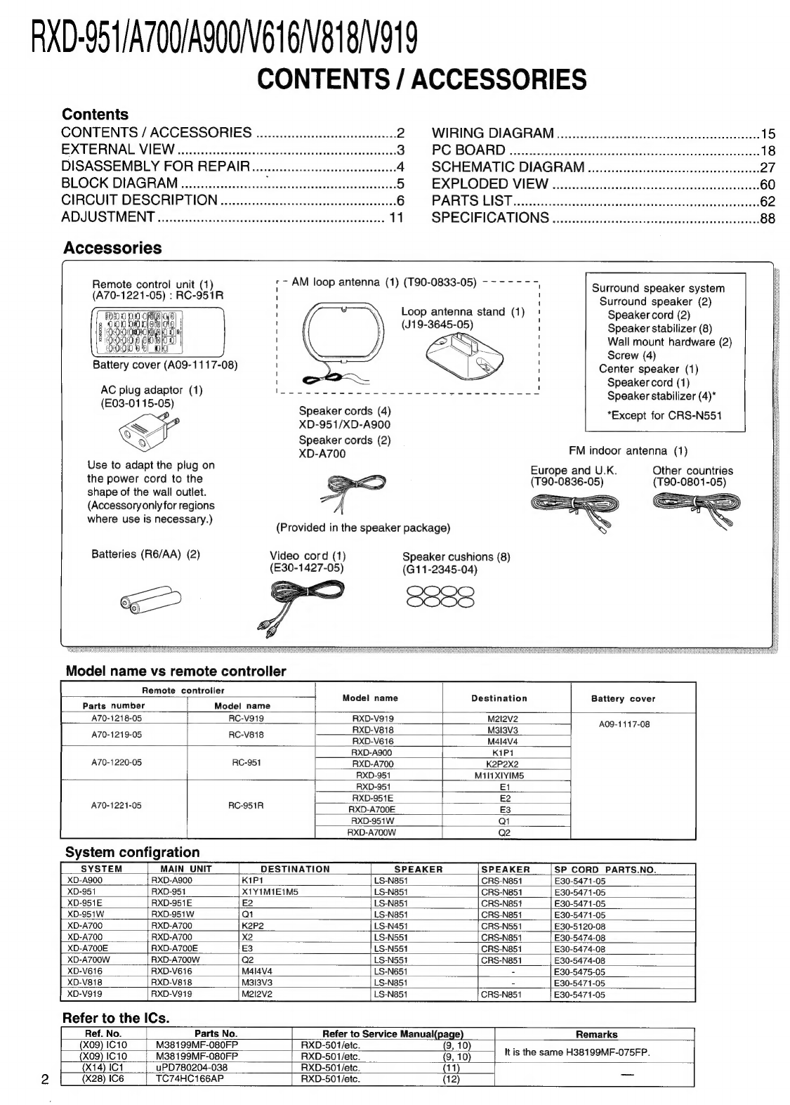
Accessories
Remote
control
unit
(1)
(A70-1221-05)
:
RC-951R
algl
|
0D)
0)
|
Battery
cover
(A09-1117-08)
AC
plug
adaptor
(1)
(E03-0115-05)
Speaker
cords
(4)
XD-951/XD-A900
Speaker
cords
(2)
Loop
antenna
stand
(1)
(J19-364:
Ls?
5-05)
q
S
Surround
speaker
system
Surround
speaker
(2)
Speaker
cord
(2)
Speaker
stabilizer
(8)
Wall
mount
hardware
(2)
Screw
(4)
Center
speaker
(1)
Speaker
cord
(1)
Speaker
stabilizer
(4)*
*Except
for
CRS-N551
SF
Use
to
adapt
the
plug
on
the
power
cord
to
the
shape
of
the
wall
outlet.
(Accessory
only
for
regions
where
use
is
necessary.)
XD-A700
FM
indoor
antenna
(1)
Other
countries
(T90-0801-05)
Europe
and
U.K.
(T90-0836-05)
(Provided
in
the
speaker
package)
Batteries
(R6/AA)
(2)
Video
cord
(1)
(E30-1427-05)
Speaker
cushions
(8)
(G11-2345-04)
Model
name
vs
remote
controller
Remote
controller
Parts
number
Model
name
Model
name
Destination
Battery
cover
A70-1218-05
RC-V919
RXD-V919
M2l2v2
A70-1219-05
RC-V818
RXD-V818
M313V3
RXD-V616
M4l4v4
A09-1117-08
A70-1220-05
RC-951
RXD-A900
K1P1
RXD-A700
K2P2Xx2
RXD-951
M1i11X1YIM5
A70-1221-05
System
configration
SYSTEM
MAIN
UNIT
RC-951R
RXD-951
RXD-951E
RXD-A700E
RXD-951W
RXD-A700W
DESTINATION
SPEAKER
SPEAKER
SP_CORD
PARTS.NO.
XD-A900
RXD-A900
K1P1
LS-N851
CRS-N851
E30-5471-05
XD-951
RXD-951
X1Y1M1E1M5
LS-N851
CRS-N851
E30-5471-05
XD-951E
RXD-951E
LS-N851
CRS-N851
E30-5471-05
XD-951W
RXD-951W
LS-N851
[CRS-N851
E30-5471-05
XD-A700
RXD-A700
LS-N451
CRS-N551
E30-5120-08
XD-A700
RXD-A700
LS-N551
CRS-N851
E30-5474-08
XD-A700E
RXD-A700E
LS-N551
CRS-N851
E30-5474-08
XD-A700W
RXD-A700W
LS-N551
E30-5474-08
XD-V616
RXD-V616
LS-N651
CRS-N851
E30-5475-05
XD-V818
RXD-V818
LS-N851
E30-5471-05
XD-V919
RXD-V919
Refer
to
the
ICs.
Ref.
No.
Parts
No.
Ma2l2v2
LS-N851
Refer
to
Service
Manual{page)
CRS-N851
E30-5471-05
Remarks
(X09)
1C10
M38199MF-O080FP
RXD-507/etc.
(9,
10)
(X09)
1C10
M38199MF-080FP
RXD-501/etc.
(9,
10)
It
is
the
same
H38199MF-075FP.
(x14)
1C1
uPD780204-038
RXD-501/etc.
(11)
(X28)
IC6
TC74HC166AP
RXD-501/etc.
(12)
RXD-951/A700/A900/V616V818/V919
EXTERNAL
VIEW
Lock
terminal
board
*
Lock
terminal
board
*
(E70-)
(E70-)
ANTENNA
El
7
LZ
is
Phono
jack
(E63-1037-05)
7)
FF}
\
(ZN
e
g
Pao
M
300u
AUX
INPUT
Power
cord
bushing
Variable
resistor
(J42-0083-05)
(R31-0096-05)
Lock
terminal
board”
(E70-)
AC
power
cord*
(E30-)
Oscillating
module
Phono
jack
(W02-1
114-05)
(E63-0130-05)
Illustration
is
RXD-V919.
*
Refer
to
parts
list
on
page
62.
3
RXD-95
1/A700/AS00V616/V818/V919
DISASSEMBLY
FOR
REPAIR
1.
How
to
remove
the
front
panel.
(1)
Turn
the
power
ON
and
then
push
the
open/close
key
to
open
the
tray.
(2)
After
removed
the
tray
cover,
push
the
open/close
key
to
close
the
tray
and
then
turn
the
power
OFF.
(3)
Remove
the
push
rivet
(D)
and
4
screws
(@,
@).
(4)
The
front
panel
can
be
separated
by
removing
the
3
screws
(@)
located
at
the
bottom
plate
of
the
front
panel.
2.
How
to
remove
the
CD
mechanism
(1)
Remove
4
screws
(©)
on
the
left
side/right
side
of
chassis.
(2)
Remove
4
screws
(©)
and
the
cap
()
on
the
rear
panel.
(3)
Disengage
the
CD
mechanism
as
FIG.2.
(4)
Connect
the
GND
plate
of
X32
PCB
and
the
chassis
with
a
alligator
clip
wire
(®).
Fig.1
3.
How
to
remove
the
mult
control
knob.
*
Remove
the
knob
by
string
(©).
4.
How
to
open
the
tray
if
not
comes
out.
(1)
From
the
rear
side
of
the
CD
mechanism,
use
a
screw
driver
or
the
like
to
turn
the
friction
arm
fully
counterclockwise.
(2)
Pull
out
the
tray
front
wards
by
hand
when
the
tray
comes
just
out.
Sz
SIDE
Fricti
Gy
ae
rc
*
As
for
details
of
items
in
the
below,
refer
to
RXD-F3
service
manual
(B51-5091-00).
(1)
How
to
detach
the
tray.
(2)
How
to
attach
the
tray.
(3)
Replacing
the
pickup.
Fig.2
ee
ee
ee
eS
a
--—S-
oS
TT
eens
SP.
OUTPUT
|
A
PHONY
Poa
eo
ere
[
(SY;
EXCEPT
RXD-
A700
"|
STEREO
SURROUND
(THD
10%)
!
Poe
et
Uo
eo
|
[Fer]
tar]
>
[a
[eaeth
UNIT
AM:
180mV/3.3«
@
t
THD
1.0%)
:
.
a
VY
|
J
ict
|
=
I
MIC1.2
|
Lt
Ict01
IC101
wat
|
aaeaET
i
7
SS
=
|
Lo]
aa
22)
BXD95'
|
aeavien
|
aasvien
|
2asvien|
2asvisa
|
easier
t
‘i.
|
laxo-a7oo
|
226vien
|
2osviea
|
iaaven
|
taaven
==
a
ee
Se
See
es
Se
ee
ae
ee,
AXD-V616
|
22.6V/69
bert
oe
Se
1
X08)
EXCEPT
RXD-V616/V818
q
AXO-V818"
(|
:26.OVG0)
-
|
(X09)
OEXCEPT
AXD-v616/ve18
|
|
(
|
(X28)
aly
REIN
AUXIN
is
|
igs
|
[ssomwari
AUX
LEVEL
|
(1/2)
J2
(EXCEPT
AXD-ve1sve18)
apap
mrt
AUX
IN
A
«
+
|
vat
|
LS
CSP.
|
AUX OUT
|
x]
-
i
TeV
]
—
fosva3ka|
|
CJ
|
P<]
-
;
4
AUX
OUT
Aes
a]
ico
8
f
i
Str
|
co)
Ic19
|
LJ
SURROUND
SP.
B
PB
AMP
|
t
-
--——
|
]
3
FF
BRP
OTHER
|
I
DOLEY
ONOFF
1A
--
cy
CHANNEL
}
Moousy
ae
|
a
Ake
7
| |
ast
(RXD-951/A900/V919)
=——
iS].
|
=
alls
|
+—}xj-
-
al
|
>)
___
RONTSE
———
|
ie
las
NY]
+
=
8
ERASE
TC74HC166AP
[PS
LOAD
zz
a
|
|
|
pie
x
|
SUB
WOOFER
SP.
Os
a8
|
4
|
—
BEAT
CANCEL
he
|
Q10,11
|
|
(AXD-A700)/.
————
:
io
'
|
AB
PHAR
|
Say
|
ar/
/\
|
i
|
frei
al
®
Baros9
| |
(013.15
Tiare
8
|
EXCEPT
RXD-
_
i
|
MOTOR:
|
ate
—
|
—
ee
ee
arn
—
|
pact
Fo
Naa
eae
Rae
ne
das
Rah
ray
ae
7
|
Ica
Ica
43
(xa2)
Ref.
No.
:
RXD-951/A700/A900
| |
-
;
|
eu
|
ee
|
[Ref.
No]:
RXD-vereveisvaia
|
|
sx
3.4
P
¥
au
|
|
eons
;
?
pape
ae
|
(CDM-27)
[tah
|
EACH
SP.
(x14)
|
(==
[eee
cat
2h
BS
i
pa
OUTPUT
Ka
T25-0050
|
|
es
IMPEG]
iy
|
¥
PHONES
|
VIDEO
|
vingo
J3
O
|
eo
C5]
PCB
|
f
|
AF
AMPISERVO
VIDEO
Wea)
C8)
|
(016,17
|
I
=a
|
same
com
es
|e
(1¢3}
AUDIO
OUT
=
|
|
OSPIDAC
|
21-23
oo
()—
MUTE
bid
x025870
oa
{
a
|
|
pea
|
[At]
|
\
|
|
DIGITAL
©)
1
Dee
029
a
l-
ie
l
163
BASO79S
OUT
|
MAIN
[POWER
Tae!
*
AC
|
4ch
BTL
DRIVER
|
uCOM
=
IC
ow
|
w
x1
TUNER
ais
t-4
i
pple
|
3|
|
:
.
SS=s=
5|
16.93¢4mHz
:
|
&
|
|
|
|
ee
me
ait
_J
O17
7
|
|
;
Moron
[oe
|
|
|
DRIVER
.
|
|
!
Ic10
Ico
">
yea
+
|
H
MAIN
u-COM
|
5
|
|
eae
|
,
or
eG
|
[IC8,9]
S
Lage
i
|
TRAVERSE
UNIT
{C4.5
MOTOR
13
|
ON
a
HP
RELAY
1)
i
l
|
|
!
40-1500
DRIVER
S
023
|
TAB409S
‘z€
|
|
fab
|
|
\g
+e
t
|
ROTARY
é
|
|
TUNER
«
ee
re
|
LF
fonven
|
e
|
|_|
2
|
|
ron
se
l
LF
Beiven
|
sw
sre
|
|
RELAY
©RXD-V616/V818:
Refer
to
the
same
(X09)
I
|
ane
on
the
RXD-501/701
|
|
UNO
Seow
Sw
|
SURROUND
RXD-951/A700/A900/
[ee
BP
a
Nee
ae
wp
ie
5
Te
ee
I
_]
vereversivers
WVYSVvId
40018
BL6M/81BN/9
9006/02
¥/150-CXe
RXD-951/A700/AS00/V616/V818V919
CIRCUIT
DESCRIPTION
1.
Initialization
1-1
Setting
of
initial
conditions
ITEMS
While
pressing
the
[ENTER]
key,
plug
the
AC
cord
into
x
PLAY
MODE
TRACK
the
AC
power
outlet.
AUTO/NTSC/PAL
AUTO
1-2
Initializing
operation
>»
AUTO
PBC
ON
¢
A
microcomputer
is
initialized
for
start
when
the
AC
*
DIGEST
OFF
power
is
turned
on
while
pressing
the
[ENTER]
key.
At
CD/VCD|
>
MEMORY
STOP
OFF
that
time,
CD
mechanism
and
CASSETTE
mecha-
>
REPEAT
OFF
nism
are
also
initialized.
*
RANDOM
OFF
¢
During
the
initial
operation,
the
display
shows
“INITIAL-
>
ACTIVE
MODE
STOP
IZE”
and
after
that
the
clock
blinks
up
on
display.
*
TIME
SINGLE
1-3
The
backup
data
and
initial
items.
*
None
backup
data
ITEMS
*
Except
RXD-V616
POWER
OFF
**
Except
RXD-V616/V818
VOLUME
45
“™
Display
[—-:-—]
BALANCE
CENTER
%
MUTING
OFF
1-4
Mechanism
initialization
x
EQ
OFF
(ROCK)
1-4-1
CD
mechanism
EQ.
MANU
FLAT
¢
Disc
unclamps
(traverse
down)
*
EX.
BASS
ON
*
Rotary
tray
rotates
(1/3
rotation)
S.
W.
*
LEVEL3
¢
If
a
mechanism
error
occurs,
“CD”
is
indicated
on
the
SRS
3D
OFF
display.
3D
LEVEL LEVEL
+5
1-4-2
DECK
mechanism
INPUT
SEL
TUNER
¢
When
initial
condition
becomes
NG
for
the
third
time,
x
DISPLAY
MODE
DISPLAY
AUTO
decide
the
error.
DEMO
OFF
The
error
condition
is
displayed
as
"X"
on
the
display.
DOLBY
PRO
LOGIC
*
|
OFF
1-4-3
Error
display
DOLBY
3
STEREO*
|
OFF
CD
X
ERR
CENTER
MODE
*
NORMAL
DELAY
TIME
*
20
msec
2.
Test
mode
of
the
receiver
CENTER
LEVEL
*
0
(-10dB)
SURROUND
LEVEL
*
|
0
(-10dB)
%*%
Refer
to
the
3.
test
mode
on
page
7,
8
of
the
Service
BAND
FM
manual
RXD-501/etc.
(B51-5420-00).
LAST
f
LOWEST
FREQUENCY
*
It
makes
description
of
addition
RXD-V919
only.
LAST
Pch
ead
(The
operation
of
the
keys)
AUTO/MONO
AUTO
Pch
TEST
f
%*%
CLOCK
AM
12:
00
***
PROG
ON
AM
12:
00
PROG
OFF
AM
12:
00
PRO
MODE
TIMER
PLAY
SOURCE
TUNER
Pch
1
EXE
OFF
OTT
OFF
TIMER
STEREO
ON
*%
SLEEP
OFF
*
¢
Input
selector
:
Except
TUNER
DIRECTION
FORWARD
*
Surround
mode
:
DOLBY
mode
(PRO
LOGIC,
3ST)
RVS
MODE
DOLBY
NR
>
A/B
%
ACTIVE
MODE
Push
Key
Active
description
K
Setting
CENTER
LEVEL
SKIP
UP
(>i)
-10
(Min)
+
O
—
+10
(Max)
SKIP
DOWN
(@<d)
|
-10
(Min)
+-
0
+
+10
(Max)
x
Setting
SURROUND
LEVEL
FF
(pe)
-10
(Min)
+
0
—
+10
(Max)
RWD
(<<)
-10
(Min)
+-
0
+
+10
(Max)
CD
PGM
DOLBY
PRO
LOGIC
ON
DUBBING
DOLBY
3
STEREO
ON
RXD-951/A700/AG00/V616V818/V919
CIRCUIT
DESCRIPTION
3.
Key
matrix
FL
driver
u-COM
(uPD780204-038)
:
(X14-)
IC1
*14)*
EXCEPT
:
RXD-V616/V818
VOLTAGE
(V)
|
ADO
(33pin)|
AD1
(32pin)
|
AD2(3ipin)
|
AD3(30pin)
|
AD4
(29pin)
|
ADS
(28pin)
|
_AD6
(27pin)
0~0.
82
POWER
EX.
BASS
CDPGM
|TUNINGUP
[COM
A/B
DOLBY
NR
0.84~1.
64
a
*4)
SOUND
|
DUBBING
|
TUNING
DOWN
|
CD
>>
TAPE
pe
|
REV
MODE
1.
66
~
2.
52
=
*2)
SRS
BAND
CDs
TAPE
|
DISC
1
2.54
~3.
38
-
INPUT
*3)
AUTO
CD
p/m
TAPE
m
DISC
SKIP
3.40
~4.
18
=
MODE
/
DEMO
|
SET
ENTER
CD
4
TAPE
—«
|
DISC2
4.20
~
4.78
TIMER
-
TAPE
@
TAPE
«<4
|
DISC3
*
2)
©
RXD-V616/V818/V919
:
KARAOKE
¢
Other
:
DISPLAY
*
3)
©
RXD-V616/V818
:
SOUND
¢
Other
:
LISTEN
MODE
4.
Main
microprocessor
4-1
Microprocessor
periphery
block
diagram
(RXD-951/A700/A900)
CD
MECHA
CDM-27
X09,
IC10
X14,
IC1
FL
DRIVER
uCOM
uPD780204
X09,
IC
11
RDS
IC
SAA6579
X32,
IC2
DSP
CXD2587Q
X09,
IC9
SPEANA
IC
BA3834SK
X28,
IC6
EXPANDER
IC
TC74HC166AP
M381
99MF-O80FP
M38199MF-083FP
u-COM
DECK
MECHA
X08,
IC3
DOLBY
IC
M62460FP
X09,
IC1
SELECTOR
IC
NJU7313AL
X08,
IC4
E.VOL
(C,S)
M62429FP
X09,
IC4
SYSTEM
IC
M62430FP
X05,
IC2
PLL
IC
LC72131
RXD-95
1/A700/A900/V616V818/V919
CIRCUIT
DESCRIPTION
(RXD-V616/V818/V919)
CD
MECHA
CDM-27
(X14)
1C16
(X28)
IC6
EXPANDER
IC
(X09)
IC10
DECK
MECHA
>
(X08)
IC3
DOLBY
IC
M62460FP
FL
DRIVER
uCOM
uPD780204
(X09)
IC1
SELECTOR
IC
NJU7313AM
M38199MF-084FP
XX
(X08)
IC4
(X32)
IC3
E.
VOL(C,
S)
M62429FP
DSP
CXD2585Q
(X09)
IC4
TONE,
SRS
M62430FP
(X32)
IC4
X05,
IC2
DAC
IC
PCM1717E
PLL
IC
LC72131
*
EXCEPT
RXD-V616/V818
4-2
Pin
description
Microprocessor
:
M38199MF-084FP
(X09,
IC
10)
RXD-951/A700/AS00V'616/V818V919
CIRCUIT
DESCRIPTION
ATT
E.
vol
attenuation
Pin
No
Pin
name
VO
Description
1
PS
IN
|
Parallel
serial
IC
input
data
2
PS
LOAD
O
Parallel
serial
IC
load
H
:
SHIFT
L:
LOAD
3
A
MUTE
O
|
Audio
mute
control
H
:
OFF
L:
ON
4
BP
IN
l
Speana
input
(A/D
converter
input)
5
JOG
CW
I
Jog
input
B
6
JOG
CCW
|
Jog
input
A
7
ENC
CW
I
Rotary
encoder
input
B
8
ENC
CCW
I
Rotary
encoder
input
A
9
H.P.
I
Headphones
switch
input
H:ON
L:
OFF
10
EMPHASIS
l
Video
CD
emphasis
11
CD
PROT
|
CD
protect
input
H
:
PROTECT
L
:
NORMAL
12
DRV
CLK
O
FL
driver
u-COM
control
clock
13
DRV
Sl
oO
FL
driver
u-COM
control
data
output
14
_DRVSO
FL
driver
u-COM
control
data
input
15
C
BUSY
O
|
Video
CD
u-COM
busy
output
(MPEG)
16
VCLOCK
O
|
Video
CD
u-COM
clock
(MPEG)
17
C
DATA
O
|
Video
CD
u-COM
data
output
(MPEG)
18
|
M
DATA
|__|
Video
CD
u-COM
data
input
(MPEG)
19
CD
CK
O
|
CDDSP
IC
clock
(CXD2587Q)
20
SQCK
O__|
CD
Sub
code
clock
(CXD2587Q)
21
CDDT
O
|
CDDSP
IC
data
(CXD2587Q)
22
SQSO
'
1
|
CD
Sub
code
input
(CXD2587Q)
23
CDXL
O
|
CD
latch
output
(CXD2587Q)
_
24
SENS
|||
CD
sense
input
(CXD2587Q)
25
CDSCK
O
|
Sense
data
reading
clock
output
(CXD2587Q)
26
_
LDON
O_|
CD
laser
output
H
:
OFF
L:
ON
27
DATA
O
|
SELECTOR/SYSTEM/DAC/DOLBY
IC
data
output
28
CLK
O
|
SELECTOR/SYSTEM/DAC/DOLBY
IC
clock
output
29
PROT
|
Protection
input
H:
PROTECTION
ON
L:
NORMAL
30
SCOR
l
Sub
code
synchronism
signal
(CXD2587Q)
31
E
DATA
O
|
E.
vol
data
output
(M62430FP)
32
ECLK
|
O
|
E.
vol
clock
output
(M62430FP)
33
P/N-O
|
Video
CD
video
mode
H
:
PAL
L:
NTSC
34
M
BUSY
|
Video
CD
u-COM
busy
input
(MPEG)
35
RESET
|
|
Reset
signal
input
H
:
NORMAL
L:
RESET
36
X
CIN
|
Timer
clock
input
(32.768kHz)
37
X
COUT
©
|
Timer
clock
output
(32.768kHz)
38
XIN
|
Main
clock
input
(8.38MHz)
39
X
OUT
O
|
Main
clock
output
(8.38MHz)
40
VSS
—
|
GND
41
PLL
DO-
I
PLL
data
input
_
42
STEREO
\
Stereo
detector
input
43
SD
|
|
SD
detector
input
44
:
CE
I
Power
failure
input
H:AC
ON
L:
AC
OFF
45
PLL
CE
oO
PLL
IC
chip
enable
(LC72131)
46
TU
EMP
O
FM
emphasis
change-over
(M
type
only)
H
:
100kHz
L
:
50kHz
!
Polar/Pilot
change-over
(Q
type
only)
-H:
POLAR
L:
PILOT
47
FL
RST
O
FL
driver
reset
control
output
48
T
MUTE
O
|
TUNER
mute
control
output
49
DRV
ST
O
|
FL
driver
u-COM
control
strobe
output
7
50
HP
RLY
oO
Headphones
relay
control
51
SEL
ST
O
|
Selector
IC
strobe
output
(NJU7313AL)
O
RXD-951/A700/AS00/V616/V818V919
Pin
name
S)
CIRCUIT
DESCRIPTION
Description
SYS
ST
System
IC
strobe
output
(M62430FP)
CS
RELAY
.CS
speaker
relay
control
H:ON
SP
RELAY
r
Speaker
relay
control
:
ON
DOL
ST
Dolby
IC
strobe
output
MON
PMON
control
>
ON
P/N-I
NTSC/PAL
changeover
>
PAL
CDRST
CD
DSP
IC
(CXD2585Q)
reset
control
:
NORMAL
M/A
i
as
TV
changeover
control
:
MANUAL
ML
DAC
IC
(PCM1717E)
strobe
output
P
RLY
=
Power
relay
control
:
ON
LMR
Loading
motor
control
(reverse)
LMF
Loading
motor
control
(forward)
:
ON
RMF
Rotary
motor
control
(forward)
:
ON
BRKM
Rotary
motor
control
(brake)
:
NORMAL
RMR
Rotary
motor
control
(reverse)
>
ON
DC
OFF
CD
DSP
IC
power
control
(CXD2587Q)
:
ON
BEAT
CANCEL
Beat
cancel
>
ON
A/B
A/B
Playback
change-over
:B
BIAS
Bias
change-over
:
ON
R
MUTE
NR
D-R/P
R/P
Deck
rec
mute
control
:
OFF
Dolby
noise
reduction
change-over
:
ON
O/O/OlO/O/OjO/OlO/OJ/O/O/O/Oj/O/O/O/O!O/OjO;O
Dolby
rec/play
change-over
Rec/play
change-over
B
CPM
B
deck
motor
control
B
SOL
B
deck
solenoid
control
ACPM
A
deck
motor
control
ASOL
XU
LLLjyL\LlLjL\|L\LlTlLT\|LyTrit
A
deck
solenoid
control
SPE3
TU/SPE2
TYP/SPE1
O;O/O/O|O/O|O|O
[ee
ome
Oe
eee
ee
0
Speana
out
3
TUNER
destination
(scan)/speana
out
2
Model
discrimination
(scan)/speana
out1
RET4~RET1
Model
discrimination
input
4~1
Discrimination
of
TUNER
destination
(DSW3~DSW0)
A-PH
A
deck
photo
sensor
input
B-PH
B
deck
photo
sensor
input
UNL
SW
CD
unload
switch
H:ON
LO
SW
CD
load
switch
:
OFF
:
ON
VCC
u-COM
power
supply
(+5V)
ST
SW
CD
mechanism
stop
switch
:
OFF
>
ON
UP
SW
CD
mechanism
up
switch
:
OFF
:
ON
DN
SW
CD
mechanism
down
switch
:
OFF
>
ON
PS
SW
CD
mechanism
position
switch
:
OFF
>
ON
CD
MUT
CD
analog
mute
:
OFF
>
ON
ZERO
CD
zero
mute
detection
:
MUTE
OFF
:
MUTE
ON
VEE
GND
AVSS
A/D
GND
VREF
10
A/D
reference
voltage