manuals.online logo
Brands
  1. Home
  2. •
  3. Brands
  4. •
  5. Kenwood
  6. •
  7. Transceiver
  8. •
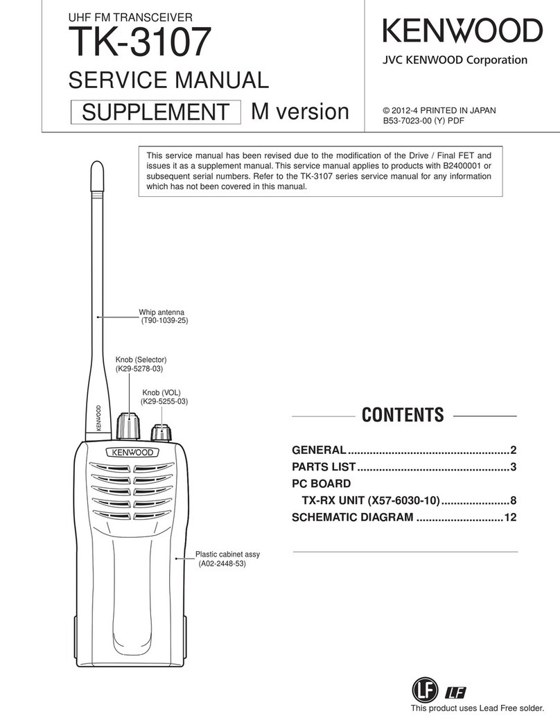
  9. Kenwood TM-241A User manual

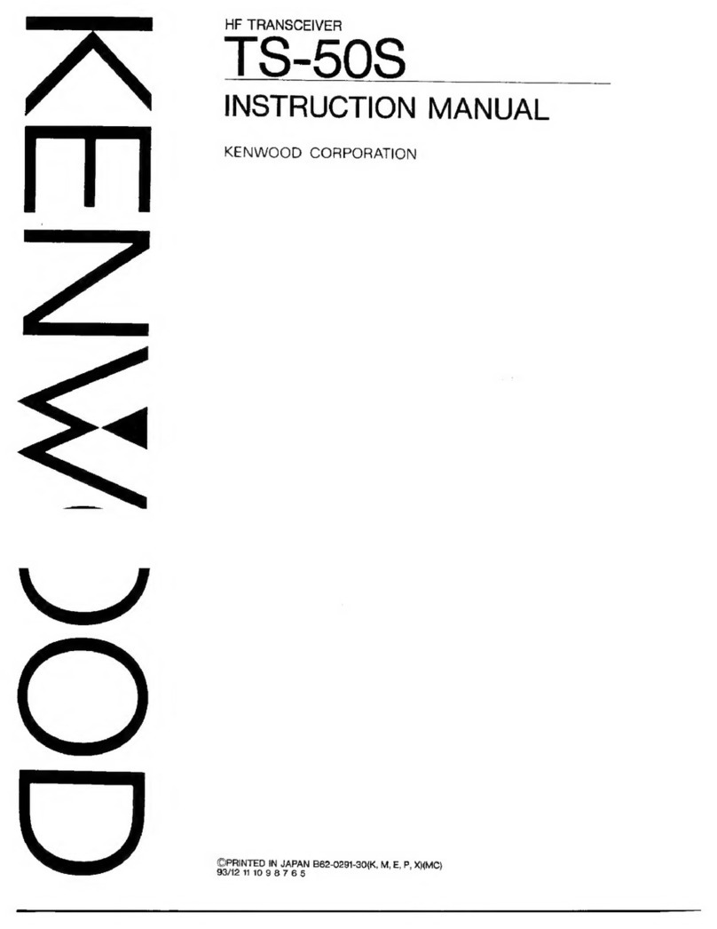
Kenwood TM-241A User manual

Other manuals for TM-241A

8

This manual suits for next models

5

Other Kenwood Transceiver manuals

Kenwood TM-221A User manual

Kenwood

Kenwood TM-221A User manual

Kenwood UBZ-LF14 User manual

Kenwood

Kenwood UBZ-LF14 User manual

Kenwood TK-5210 User manual

Kenwood

Kenwood TK-5210 User manual

Kenwood TK-7302H User manual

Kenwood

Kenwood TK-7302H User manual

Kenwood TM-642A User manual

Kenwood

Kenwood TM-642A User manual

Kenwood TR-7730 User manual

Kenwood

Kenwood TR-7730 User manual

Kenwood TM-481A User manual

Kenwood

Kenwood TM-481A User manual

Kenwood TK-3180-K2 User manual

Kenwood

Kenwood TK-3180-K2 User manual

Kenwood TS-700 User manual

Kenwood

Kenwood TS-700 User manual

Kenwood TS-700A User manual

Kenwood

Kenwood TS-700A User manual

Kenwood TS-870S User manual

Kenwood

Kenwood TS-870S User manual

Kenwood NEXEDGE NX-700 series User manual

Kenwood

Kenwood NEXEDGE NX-700 series User manual

Kenwood TS-450S User manual

Kenwood

Kenwood TS-450S User manual

Kenwood FreeTalk XL User manual

Kenwood

Kenwood FreeTalk XL User manual

Kenwood Nexedge NX-720H User manual

Kenwood

Kenwood Nexedge NX-720H User manual

Kenwood UBZ-LF14 User manual

Kenwood

Kenwood UBZ-LF14 User manual

Kenwood TS-950 series User manual
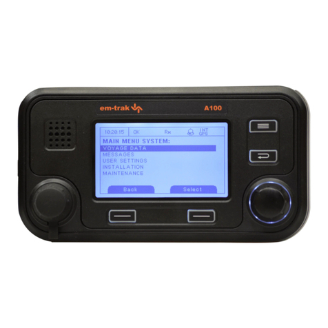
Kenwood

Kenwood TS-950 series User manual
Kenwood TH-D7 A Operating instructions

Kenwood

Kenwood TH-D7 A Operating instructions

Kenwood TR-7730 User manual

Kenwood

Kenwood TR-7730 User manual

Kenwood TK-2260EX User manual

Kenwood

Kenwood TK-2260EX User manual

Kenwood TR-851A User manual

Kenwood

Kenwood TR-851A User manual

Kenwood TM-D710A User manual

Kenwood

Kenwood TM-D710A User manual

Kenwood TS-600 User manual

Kenwood

Kenwood TS-600 User manual

Kenwood TM-271A User manual

Kenwood

Kenwood TM-271A User manual

Popular Transceiver manuals by other brands

City Theatrical SHoW DMX SHoW Baby user manual

City Theatrical

City Theatrical SHoW DMX SHoW Baby user manual

Standart Horizont HX407 owner's manual

Standart Horizont

Standart Horizont HX407 owner's manual

B&G V90S quick start guide

B&G

B&G V90S quick start guide

VictelGlobal ALK300 series Operation manual

VictelGlobal

VictelGlobal ALK300 series Operation manual

Cactus Wireless Flash Transceiver V6 user manual

Cactus

Cactus Wireless Flash Transceiver V6 user manual

Yaesu FT-11R user guide

Yaesu

Yaesu FT-11R user guide

Skanti TRP 5000 instruction manual

Skanti

Skanti TRP 5000 instruction manual

ELECRAFT KX3 Installation and operation guide

ELECRAFT

ELECRAFT KX3 Installation and operation guide

American Lighting DMX512 quick start guide

American Lighting

American Lighting DMX512 quick start guide

Furuno FM-77 Operator's handbook

Furuno

Furuno FM-77 Operator's handbook

Yaesu FT-7B manual

Yaesu

Yaesu FT-7B manual

Mizuho MX-2 Operating & assembly instruction

Mizuho

Mizuho MX-2 Operating & assembly instruction

Blitz MJ-398U instruction manual

Blitz

Blitz MJ-398U instruction manual

Utilicom LongRanger 2050 Operator's manual

Utilicom

Utilicom LongRanger 2050 Operator's manual

Standart HX290UKA Service manual

Standart

Standart HX290UKA Service manual

Altronix Pace1PTM installation guide

Altronix

Altronix Pace1PTM installation guide

Kirisun PT2208 instruction manual

Kirisun

Kirisun PT2208 instruction manual

ELECRAFT KX2 manual

ELECRAFT

ELECRAFT KX2 manual

manuals.online logo
manuals.online logoBrands
  • About & Mission
  • Contact us
  • Privacy Policy
  • Terms and Conditions

Copyright 2025 Manuals.Online. All Rights Reserved.

COO/AN3»
144MHz
FM
TRANSCEIVER
TM-241A/241E
430/440MHz
FM
TRANSCEIVER
TM-441A/441E
1200MHz
FM
TRANSCEIVER
TM-S41A/S41E
(
INSTRUCTION
MANUAL
KENWOOD
CORPORATION
Thank
you
for
purchasing
this
new
transceiver.
IMPORTANT:
Please
read
this
instruction
manual
carefully
before
placing
your
transceiver
in
service.
SAVE
THIS
INSTRUCTION
MANUAL.
CAUTION:
Long
transmission
or
extended
operation
in
the
|
ІНІ
power
mode
might
cause
the
rear
of
this
|
i
i
transceiver
to
get
warm.
Do
not
place
the
transceiver
where
the
heat
sink
(rear
panel)
might
come
in
contact
with
plastic
ог
vinyl
surfaces.
This
instruction
Manual
covers
the
following
models.
TM-241A:
144MHz
FM
TRANSCEIVER
(U.S.A.
and
general
markets)
TM-241E:
144MHz
FM
TRANSCEIVER
(U.K.
and
European
markets)
ТМ-441А:
440MHz
FM
TRANSCEIVER
(U.S.A.
only)
TM-441A:
430MHz
FM
TRANSCEIVER
(General
markets)
ТМ-441Е:
430MHz
FM
TRANSCEIVER
(U.K.
and
European
markets)
ТМ-541А:
1200MHz
FM
TRANSCEIVER
(U.S.A.
only)
TM-541E:
1200MHz
FM
TRANSCEIVER
(European
markets)
NOTE:
lf
disregarded,
inconvenience
only,
no
risk
of
equipment
damage
or
personal
injury.
CAUTION:
Equipment
damage
may
occur,
but
not
personal
injury.
FCC
WARNING
This
equipment
generates
or
uses
radio
frequency
energy.
Changes
or
modifications
to
this
equipment
may
cause
harmful
interference
unless
the
expressly
approved
іп
the
modifications
—
are
instruction
manual.
The
user
could
lose
the
authority
to
operate
this
equipment
if
an
unauthorized
change
or
modification
is
made.
CONTENTS
1.
gr
de
а.
BEFORE
OPERATION
.........
sac
ts
ње
4
SPECIFICATIONS
уснаа
NE
RS
6
ACCESSORIES
аа
istbeses
7
INSTALLATION
INSTRUCTIONS
......
7
OPERATION
CONTROL
ЕЏМСТОК5..................
10
RECEIVER
OPERATION
Reception
...............
———
16
Frequency
Selection
...................
17
Frequency
Step
Selection
..............
17
Programmable
VFO
Tuning
Limits
......
18
АіТ(ТМ-541А/Е
опіу)..................
19
TRANSMITTER
OPERATION
.............
20
Time-out
Timer
(TOT)
.................
20
MEMORY
Microprocessor
Memory
back-up
.......
21
Initial
State
acc.
аз
VR
En
ES
qa
utat
ud
21
Microprocessor
Initialization
...........
21
Memory
Channel
.....................
21
Memory
Contents
«coss
EXER
22
Memory
Entry:
соқалар
eei
di
ovs
22
Memory
Channel
Recall
...............
24
Memory
Sit:
о
ou
за
ier
E
s
24
SCAN
Scan
Operation
сеанса
ues
а
Sa
25
6.
7.
Hold/Resume
Programming
...........
25
Band
Scam.
oos
terza
daten
Е
ло
26
Programmable
Band
Scan
.............
26
Memory
Channel
Scan
................
27
Memory
Channel
Lockout
.............
27
Priority
Alert
Function
................
28
REPEATER
OPERATIONS
Transmitter
Offsets
...................
28
Reverse
Function
.....................
29
Ттопе:Ореѓапоп:.
“асьохтаедфь
жееытжа
29
Tone
Frequency
Selection
.............
29
Autopatch
(U.S.A.
version
only)
........
30
TONE
/
CTCSS
OPERATION..........
30
DTSS
(Dual
Tone
Squelch
System)
OPERATION
зена
RR
31
DRS
(Digital
Recording
System)
OPERATION:
„о
RE
RR
des
34
PAGING):
аон
оо
ован
EV
41
TONE
ALERT
SYSTEM
...............
47
APO
(Automatic
Power
Off)
............
48
DIMCUimmab).
оа
ба
xe
eet
cater
danse
48
ВЕЕР
essai

49
LOCK/A.LOOK
.......................
49
BLOCK
DIAGRAM
and
SCHEMATIC
DIAGRAM
Another
sheet
MAINTENANCE
.....................
50
IN
CASE
OF
DIFFICULTY
...........
51
8.
OPTIONAL
ACCESSORIES
...........
52
A
WARRING);
BEFORE
OPERATION
TO
PREVENT
ELECTRIC
SHOCK,
FIRE
AND
OTHER
INJURY.
PLEASE
NOTE
THE
FOLLOWINGS:
To
avoid
risk
of
electric
shock,under
no
circumstances
should
the
unit
be
opened.
Do
not
place
this
unit,where
it
will
be
exposed
to
direct
sunlight
or
close
to
heating
appliances.
To
ensure
good
ventilation,
do
not
put
anything
on
top
of
the
cabinet
and
allow
at
least
15
cm
(6
Inches)
of
space
behind
the
unit.
The
power
requirement
is
13.8
VDC.
Never
attempt
connection
to
a
24
VDC
source.
Do
not
place
the
unit
in
areas
off
excessive
dust,
high
humidity
or
on
unstable
surfaces.
Do
not
drop
pieces
of
metal,
needles,
coins
and
other
electrically
conductive
materials
into
the
unit.
Do
not
touch
the
power
plug,
when
your
hands
are
wet.
Do
not
ри!
the
power
cord,
when
disconnecting
it
from
the
AC
wall
outlet.
Grasp
the
plug
and
ensure
that
your
fingers
do
not
touch
the
live
pins.
If
an
abnormal
odor
or
smoke
is
detected,
immediately
turn
the
power
off
and
pull
out
the
power
plug.
Contact
the
KENWOOD.
service
station
or
our
dealer.
CLEANING
1.
Turn
the
power
off,
before
cleaning
the
unit.
2.
Do
not
use
any
type
of
abrasive
pad,
thinner,
benzine
or
any
substances
which
may
damage
the
unit.
3.
Wipe
the
front
panel
and
other
exterior
surfaces
of
the
unit
with
a
soft
dry
cloth
or
a
soft
cloth
lightly
moistened
with
water.
Output
(5%
distortion)
2
SPECIFICATIONS
ТМ-241А/Е
|
TM-441Ausaicanaca
ТМ-441Е
|
Frequency
range
MHz
430
to
440
|
1240
to
1300
мовам
|
Antenna
impedance
са
аашаа
E
Operating
temperature
©
|
Power
requirements
-
Ground
Negative
.
gramen
Less
than
ТОА
Less
than
0.6A
Frequency
stability
Less
than
+10ppm
Dimensions
(WXH
XD)
(mm)
(Projections
included)
140
x40
X
160(5-1/2"
х1-37/64”х6-19/64”)
(140X40X172(51/2"x
1-37/64"
X
6-25/32")
Weight
(kg)
Hl
50W
Output
power
2
MID
Approx
OW
—
|
aoiw
CdS
5
LOW
Approx.
5W
E
с
Spurious
radiation
Less
than
—
60
dB
Е
Audio
distortion
(at
60%
modulation)
Less
than
3%
(300
to
3000
Hz)
Intermediate
frequency
lst/2nd
|
30.825MHz/455kHz
@
|
Selectivity
—6dB:
More
than
12
kHz
6008
Less
than
24
kHz
d
More
than
2
W
across
8
Q
loads
External
speaker
impedance
>
С
0)
=
m
m
—
A
EN
6
-—
ы
со
80
2
Recommended
duty
cycle:
1
minute
Transmit,
3
minutes
Reception
Circuits
and
ratings
are
subject
to
change
without
notice
due
to
advancement
in
technology.
3
ACCESSORIES
Unpack
your
new
transceiver
carefully,
and
examine
it
for
visible
damage
If
the
equipment
has
been
damaged
іп
shipment,
notify
the
transportation
company
immediately.
Save
the
boxes
and
packing
material
for
future
shipping.
The
following
accessories
should
be
included
in
the
box
with
the
transceiver.
DTMF
Microphone
(U.S.A.
CANADA
only)
.........
or
Dynamic
Microphone
(GENERAL
market
only)
.......
or
Dynamic
Microphone
(EUROPE
market
only)
........
Microphone
Hook
(U.S.A.
CANADA
only)
........
Mobile
Mounting
Kit
Bracket
оган
Screw
set
..............
Self
tapping
Screw
(U.S.A.
CANADA
LL
Hex
wrench:
оаа
saad
Stacking
plate
(TM-441A/441E/541A/541E)..
T91-0380-X5
1
ea.
T91-0379-X5
1
ea.
T91-0382-X5
1
ea.
J20-0319-24
1
ea.
J29-0436-03
1
ea.
N99-0331-05
1
ea.
N46-3010-46
2
ea.
W01-0414-04
1
ea.
J21-4147-14
2
ea.
DC
power
Cable
.............
E30-2111-05
1
ea.
Fuse
(TM-241A/241E:
15A)..
ҒО5-1531-05
1
ea.
(TM-441A/441E:
10A)..
FO5-1031-05
1
ea.
(TM-541A/5A1E:
8A)...
FO5-8021-05
1
ea.
Instruction
Manual
...........
В62-0031-ХХ
1
copy
Waranty
Card
rorot
жаа
EE
Fx
MS
l
ea.
(U.S.A.,
CANADA
,
EUROPE
market
s
only)
4
INSTALLATION
INSTRUCTIONS
4-1
INSTALLATION
Mounting
Bracket
When
installing
the
transceiver
in
a
vehicle
consider
the
ease
of
operation
and
safety
when
selecting
the
location
for
the
mounting
bracket.
1.
Install
the
bracket
using
the
supplied
flat
washers
and
self
tapping
screws
(
4
pcs.each).
2.
Attach
the
transceiver
loosely
using
the
4
SEMS
screws.
3.
Align
the
grooves
in
the
bracket
with
the
transceiver's
screws
(
Fig.
A)
and
slide
the
transceiver
to
the
rear.
4.
Adjust
the
viewing
angle
in
the
bracket
to
the
desired
position
(
Fig.
B).
5.
Hold
the
transceiver
in
place
and
tighten
the
4
SEMS
screws
using
the
supplied
wrench.
4-2
CONNECTION
4-2-1
Mobile
Installations
Cautions
:
1.
Before
installing
the
power
cable,
be
sure
to
remove
the
negative
lead
from
the
battery
for
safety.
2.
After
installation
and
wiring,
be
sure
to
double
check
for
correct
installation
before
reconnecting
|
the
negative
lead
to
the
battery
terminal.
|
3.
If
the
fuse
opens,
be
sure
to
check
that
each
.
conductor
has
not
been
damaged
by
short.
circuiting,
etc.
Then
replace
with
a
new
fuse
of
|
the
same
rating.
4.
After
completing
the
wiring,
wrap
the
fuse
holder
with
heat
resistant
tape
to
protect
against
heat
and
moisture.
5.
Do
not
remove
the
fuse
even
if
the
power
cable
is
too
long.
A.
Battery
Connections
Connect
the
power
cable
directly
to
the
battery
terminals.
Using
of
the
cigarette
lighter
socket
will
lead
to
a
poor
connection,
and
will
result
in
poor
performance.
Pay
close
attention
to
the
polarity
of
the
cables
when
connecting
them
to
the
battery.
Make
sure
the
positive
{
+)
and
negative
(-)
lead
polarity
is
correct
when
connecting
to
the
battery.
Engine
аша
ыт
сты
Passenger
compartment
Fuse
R
Select
a
location
whare
E
the
power
cable
is
pro-
l
!
tected
from
heat,
mois-
|
ture
or
abrasion
when
`
,
Securing
ће
the
cabe.
,
Red
9
\
To
the
\
transceiver
Make
sure
the
cable
does
not
directly
contact
the
edge
of
the
hole
by
using
a
grommet.
cable
Chassis
or
ee
PENES,
fire
wall
Battery
W
|f
the
wiring
hole
in
the
fire
wall
or
chassis
is
too
small,
disas-
semble
the
fuse
holder
to
thread
the
wire
through
the
hole.
From
passenger
compartment
Thread
like
this
B.
Ignition
Noise
This
transceiver
has
been
designed
to
suppress
ignition
noise;
however,
if
excessive
noise
is
present,
it
may
be
necessary
to
use
suppressor
spark
plugs
(with
resistors).
4-2-2
Fixed
Station
A
regulated
DC
power
supply
(13.8
VDC
capable
of
supplying
at
least
11
amperes)
is
required.
PS-33
is
recommended.
outlet
until
81
other
connections
have
been
made.
2.
Before
connecting
and
disconnecting
the
power
connector,
be
sure
to
turn
OFF
the
POWER:
switches
of
both
the
transceiver
and
the
DC
power
supply.
|
3.
Observe
polarity
of
the
DC
power
cable.
The
'
transceiver
operates
on
13.8
VDC,
negative
ground.
Battery
polarity
must
be
correct.
The
power
cable
is
color
coded
:
Red
—
+
(Positive
polarity)
Black
—^
—
(Negative
polarity)
4-2-3
Antenna
The
type
of
antenna
that
is
used
will
greatly
affect
the
performance
of
the
transceiver.
Use
a
properly adjusted
antenna,
of
good
quality,
to
enable
your
transceiver
to
perform
at
its
best.
The
antenna
input
impedance
is
50
ohms.
Use
50-ohm
coaxial
cable
such
as
RG-8U
or
8D-2V
for
this
connection.
If
the
antenna
is
far
from
the
transceiver
the
use
of
low
loss
coaxial
cable,
such
as
RG-
8U
is
recommended.
Match
the
impedance
of
the
coaxial
cable
and
that
of
the
antenna
so
that
the
SWR
is
less
than
1.5
to
1.
The
protection
circuit
in
the
transceiver
will
activate
if
the
SWR
is
particularly
poor
(greater
than
3
to
1).
High
SWR
values
will
cause
the
transmitter
output
to
drop,
and
may
lead
to
TVI
or
BCI
reports.
|
Caution
:
|
|
We
recommend
that
you
install
a
high
quality
lightening
arrestor
in
your
antenna
lines
for
protection
against
fire,electric
_
shock,personal
injury,or
damage
to
the
radio
itself.
<<
M
Àဗ—Á
——
—
A
5
OPERATION
5-1-1
CONTROL
FUNCTIONS
(22
POWER
switch
Press
to
turn
the
transceiver
on
or
off.
Press
the
VFO/MPV
or
MR/M
key
and
switching
the
power
on
will
reset
the
VFO
or
MEMORY.
The
microphone
PF
key
can
be
programmed
when
the
power
is
switched
on.
@
Tuning
control
This
control
is
used
to
select
the
desired
transmitter
/receiver
frequency,
MHz
step,
memory
channel,
frequency
step,
tone
frequency,
scan
direction,
etc.
(3
VOL
control
This
control
is
used
to
adjust
the
volume
from
the
internal
and
external
speaker
(if
used).
Clockwise
rotation
will
increase
the
—
volume
and
counterclockwise
rotation
will
decrease
the
volume.
@
SQL
(Squelch)
control
This
control
is
used
to
select
the
desired
squelch
threshold
level.
10
ALOCK
~
~
FEV
>
99606885588
AL
CTCSS
g
i
Ка
Б
5)
LOW/DIM
key
LOW
This
function
is
used
to
select
the
transmit
output
power
level
(НЕ,
MID(Except
TM-541A/E),
or
LOW).
DIM
This
function
is
used
to
select
the
intensity
of
the
front
panel
display
illumination.
(See
page
48)
Pressing
the
F
key
for
longer
than
1
second
and
then
press
the
LOW/DIM
key
while
the
F
indicator
is
flash-
ing
will
turn
the
time-out
timer
function
on
and
off.
|
(6)
Microphone
connector
Attach
the
supplied
microphone
to
this
connector.
Тһе
pin
out
of
the
connector
is
shown
in
the
accompanying
illustration.
%
GND
T
GNO
{Microphone
audio)
$
MIC
(Microphone
Audio)
(3)
RX
Audio
Output
2
PTT
(Approx
100
mV/10
к
ohm)
(Push
to
Talk)
3:
DWN
@
UP
5)
В
VOC
(Max
150
mA)