manuals.online logo
Brands
  1. Home
  2. •
  3. Brands
  4. •
  5. Kenwood
  6. •
  7. Transceiver
  8. •
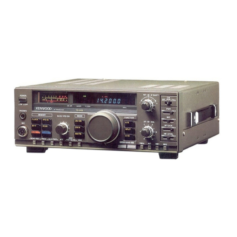
  9. Kenwood TS-830S User manual

Kenwood TS-830S User manual

Other manuals for TS-830S

5

Other Kenwood Transceiver manuals

Kenwood NEXEDGE NX-700 series User manual

Kenwood

Kenwood NEXEDGE NX-700 series User manual

Kenwood TM-733A User manual

Kenwood

Kenwood TM-733A User manual

Kenwood TS-990S User manual

Kenwood

Kenwood TS-990S User manual

Kenwood TK-8108H User manual

Kenwood

Kenwood TK-8108H User manual

Kenwood TH-255A User manual

Kenwood

Kenwood TH-255A User manual

Kenwood TK 3200U2P - Protalk UHF - Radio User manual

Kenwood

Kenwood TK 3200U2P - Protalk UHF - Radio User manual

Kenwood TS-120S User manual

Kenwood

Kenwood TS-120S User manual

Kenwood TK-868GD User manual

Kenwood

Kenwood TK-868GD User manual

Kenwood TK-3170 User manual

Kenwood

Kenwood TK-3170 User manual

Kenwood TS-140S User manual

Kenwood

Kenwood TS-140S User manual

Kenwood TK-3101K User manual

Kenwood

Kenwood TK-3101K User manual

Kenwood TS-440S User manual

Kenwood

Kenwood TS-440S User manual

Kenwood Nexedge NX-300GE User manual

Kenwood

Kenwood Nexedge NX-300GE User manual

Kenwood TM-D700 E User manual

Kenwood

Kenwood TM-D700 E User manual

Kenwood TS-590S Manual

Kenwood

Kenwood TS-590S Manual

Kenwood TK-940 User manual

Kenwood

Kenwood TK-940 User manual

Kenwood TS-5700 User manual

Kenwood

Kenwood TS-5700 User manual

Kenwood TK-5210 User manual

Kenwood

Kenwood TK-5210 User manual

Kenwood TK-7302E User manual

Kenwood

Kenwood TK-7302E User manual

Kenwood ProTalk NX-P500 User manual

Kenwood

Kenwood ProTalk NX-P500 User manual

Kenwood TK-2202 User manual

Kenwood

Kenwood TK-2202 User manual

Kenwood TK-480 User manual

Kenwood

Kenwood TK-480 User manual

Kenwood TS-940S User manual

Kenwood

Kenwood TS-940S User manual

Kenwood TS-50S User manual

Kenwood

Kenwood TS-50S User manual

Popular Transceiver manuals by other brands

City Theatrical SHoW DMX SHoW Baby user manual

City Theatrical

City Theatrical SHoW DMX SHoW Baby user manual

Standart Horizont HX407 owner's manual

Standart Horizont

Standart Horizont HX407 owner's manual

B&G V90S quick start guide

B&G

B&G V90S quick start guide

VictelGlobal ALK300 series Operation manual

VictelGlobal

VictelGlobal ALK300 series Operation manual

Cactus Wireless Flash Transceiver V6 user manual

Cactus

Cactus Wireless Flash Transceiver V6 user manual

Yaesu FT-11R user guide

Yaesu

Yaesu FT-11R user guide

Skanti TRP 5000 instruction manual

Skanti

Skanti TRP 5000 instruction manual

ELECRAFT KX3 Installation and operation guide

ELECRAFT

ELECRAFT KX3 Installation and operation guide

American Lighting DMX512 quick start guide

American Lighting

American Lighting DMX512 quick start guide

Furuno FM-77 Operator's handbook

Furuno

Furuno FM-77 Operator's handbook

Yaesu FT-7B manual

Yaesu

Yaesu FT-7B manual

Mizuho MX-2 Operating & assembly instruction

Mizuho

Mizuho MX-2 Operating & assembly instruction

Blitz MJ-398U instruction manual

Blitz

Blitz MJ-398U instruction manual

Utilicom LongRanger 2050 Operator's manual

Utilicom

Utilicom LongRanger 2050 Operator's manual

Standart HX290UKA Service manual

Standart

Standart HX290UKA Service manual

Altronix Pace1PTM installation guide

Altronix

Altronix Pace1PTM installation guide

Kirisun PT2208 instruction manual

Kirisun

Kirisun PT2208 instruction manual

ELECRAFT KX2 manual

ELECRAFT

ELECRAFT KX2 manual

manuals.online logo
manuals.online logoBrands
  • About & Mission
  • Contact us
  • Privacy Policy
  • Terms and Conditions

Copyright 2025 Manuals.Online. All Rights Reserved.

GOO/ANAD
HF
TRANSCEIVER
TS-8305
INSTRUCTION
MANUAL
KENWOOD
CORPORATION
C’PRINTED
IN
JAPAN
B50-8048-30(K,
M,
T,
W)
89/121110987654321
88/12111098
AFTER
UNPACKING
It
is
advisable
to
save
all
original
packing
cartons
(inner
and
outer)
to
protect
your
valuable
transceiver
from
damage
should
you
wish
to
transport
it
for
remote
operation
or
ship
it
for
after-sales
service.
The
following
explicit
definitions
apply
in
this
manual.
Be
sure
to
read
these
definitions:
WARNING:
Personal
injury
may
occur
—
do
not
disregard.
CAUTION:
Read
Operating
Manual
Section
4.
before
placing
transmitter
in
service.
WARNING:
HIGH
VOLTAGES
PRESENT.
CONTENTS
NOTE:
If
disregarded,
inconvenience
only
no
damage
or
personal
injury.
CAUTION:
Equipment
damage
may
occur,
but
not
personal
injury.
SPECIFICATIONS...
ae
9
SECTION
1.
INTRODUCTION
AND
FEATURES....
4
SECTION
2.
INSTALLATION.
2.1.
Unpacking
2.2
Operating
Location
2.3.
Cabling
2.4
Microphone
2.5
Key
2.6
External
Speaker
and
Headphones
2.7.
Ground
2.8
Antenna
SECTION
3.
CONTROLS
AND
THEIR
FUNCTIONS
8
3.1
Front
Panel
3.2
Rear
Panel
SECTION
4.
OPERATION...
4.1
Reception
(I)
(1)
Basic
Procedures
for
Receive
Operation
(2)
WWV
Reception
4.2
Reception
(II)
(1)
RF
ATT
Switch
(2)
RF
Gain
Control
(3)
AGC
(Automatic
Gain
Control)
(4)
RIT/XIT
(5)
VBT
Control
(Variable
Bandwidth
Tuning)
(6)
IF
Shift
(7)
VBT
and
IF
Shift
Combination
(8)
Notch
Control
(9)
Noise
Blanker
(NB)
(10)
Tone
Control
.
14
4.3
Transmission
(I)
(1)
SSB
Operation
4.4
Transmission
(II)
(1)
Speech
Processor
(2)
VOX
(Voice
Operated
Transmit)
Operation
(3)
XIT
(Transmitter
Incremental
Tuning)
(4)
Monitor
(5)
CW
Operation
4.5
Fixed
Channel
Operation
4.6
Digital
Display
Calibration
4.7.
Analog
Dial
Calibration
SECTION
5.
OPTIONAL
ACCESSORIES
5.1.
Optional
Accessories
5.2
Installation
of
Accessories
SECTION
6.
MAINTENANCE
AND
ALIGNMENT
..
26
6.1
General
6.2
Service
Position
6.3.
Receiver
Adjustments
6.4
Transmitter
Adjustments
6.5
Transmitting
on
WARC
BANDS
6.6
Analog
Dial
Adjustment
6.7.
Operation
On
220
or
240V
AC
6.8
Ordering
Spare
Parts
6.9
Service
TROUBLESHOOTING
BLOCK
DIAGRAM....
SCHEMATIC
DIAGRAM
INTERNAL
VIEW
TS-830
Unt
cH0s44eeTEUE
TUDO
caUnNoecHn
TES
oeTNET
HHUA
[GENERAL]
Frequency
Range
Power
Requirement
Power
Consumption
Dimensions
[TRANSMITTER]
*Final
Power
Input
Audio
Input
Impedance
RF
Output
Impedance...
Frequency
Stability
Carrier
Suppression
Sideband
Suppression..
Spurious
Radiation.
Harmonic
Radiation
..
Audio
Freq.
Response
..
3rd
Order
Intermodulation
Distortion.
ALC
Input
Linear
Amp
Relay
Contact
Rating
...
[RECEIVER]
Receiver
Sensitivity
Image
Ratio
IF
Rejection
Receiver
Selectivity
SSB/CW
WIDE..
CW
NARROW
...
Variable
Bandwidth
SSB
with
2.4
kHz
filter
CW
with
500
Hz
filter
Notch-filter
Attenuation
....
Audio
Output
Impedance
..
Audio
Output
..
S
SPECIFICATIONS
tvsennnnescenesennntocannnesatanteseuntgeseenenyscguetoscttnnscutntosetthto
MHtys<440to-cngyscuuadnscQ4tdaseQnng
cD
scAEE
Deanne
EE
TEU
AHEM
anne
160m
Band
1.8
~
2.0MHz
80m
Band
3.5
~
4.0MHz
40m
Band
7.0
~
7.3MHz
*
30
m
Band
10.1
~
10.15
MHz
(10.0
MHz
WWV)
20
m
Band
14.0
~
14.35
MHz
*
17
m
Band
18.068
~
18.168
MHz
15
m
Band
21.0
~
21.45
MHz
*
12
m
Band
24.89
~
24.99
MHz
10
m
Band
28.0
~
29.7
MHz
..
SSB/CW
.
120V
AC
(220V,
240V
modifiable),
50/60
Hz
Transmit:
295
watts
Receive:
32
watts
(with
heaters
off)’
..
333
(13.3)
x
133
(5.3)
x
333
(13.3)
mm
(inch)
.
13.5
kg
(29.8
Ibs)
220W
PEP
for
SSB
operation
180W
DC
for
CW
operation
5002
~
50
kQ
..
502
~
750
.
Within
1
kHz
during
the
first
hour
after
1
minute
of
warmup.
Within
100
Hz
during
any
30
minute
period
after
warmup.
Better
than
40 dB
.
Better
than
60
dB
Better
than
60 dB
Better
than
40
dB
400
to
2,600
Hz,
within
—6
dB
...
Better
than
—36
dB
..
—10V
DC
MAX
.
100V
DC
1A
...
0.25
nV
at
10
dB
S+N/N
..
Better
than
60
dB
Better
than
80 dB
..
2.4
kHz
(—6
dB),
3.6
kHz
(—60
dB)
.
With
YK-88C
(option)
500
Hz
(—6
dB),
1.5
kHz
(—60
dB)
270
Hz
(—6
dB),
1.1
kHz
(—60
dB)
500
Hz
(—6
dB),
820
Hz
(—60
dB)
250
Hz
(—6
dB),
500
Hz
(—60
dB)
With
YK-88CN
(option)
With
YG-455C
(option)
With
YG-455CN
(option)
500
Hz
~
2.4
kHz
(—6
dB)
continuously
variable
500
Hz
~
150
Hz(—6
dB)
continuously
variable
With
optional
filter
YK-88C
and
YG-455C
added.
....
Better
than
40
dB
-8~
162
.
1,5W
(8Q)
*Will
transmit
on
the
new
30,
17,
and
12
meter
bands.
Diodes
installed
for
preventing
accidental
transmission
before
government
amateur
authorization.
NOTE:
The
circuit
and
ratings
may
change
without
notice
due
to
developments
in
technology.
Pe
POU
SECTION
Ts
aN
uuHnoseHEdtncUntoscauntpocenegyscunyscuuatossnttnocenegnscyanosenetenccteney-cuttto-ctntts-cnuni
sa
1.1
KENWOOD
TS-830S
The
TS-830S
is
a
highly
sophisticated
solid
state
Amateur
band
transceiver
employing
only
three
vacuum
tubes.
Operating
on
all
Amateur
bands
between
1.8
and
29.7
MHz,
this
unit
is
constructed
modularly.
The
TS-830S
includes
many
built-in
features
usually
found
as
extras
on
other
transceivers.
Included
are
VOX,
25
kHz
calibrator,
RIT,
RF
attenuator,
and
an
effective
noise
blanker.
The
TS-830S
also
includes
automatic
gain
control
(AGC),
automatic
level
control
(ALC),
semi-break-in
CW
with
sidetone,
a
speech
processor,
speaker
and
built-in
AC
power
supply.
Designed
for
operation
on
SSB
or
CW,
the
TS-830S
delivers
more
than
220
watts
PEP
input.
Any
complicated
electronic
device
will
be
damaged
if
operated
incorrectly,
and
this
transceiver
is
no
exception.
Please
read
all
of
the
operating
instructions
before
putting
your
TS-830S
on
the
air.
1.2
FEATURES
1.
Interference-free
DX
operation
*
Variable
bandwidth
IF
filter
circuit
(VBT)
The
built-in
VBT
(Variable
Bandwidth
Tuning)
circuit
al-
lows
IF
filter
pass-bandwidth
to
be
varied
as
you
wish
to
eliminate
unpleasant
interference.
It
is
adjustable
independent
of
the
IF
Shift.
*IF
shift
circuit
The
IF
SHIFT
(also
called
pass-band
tuning)
is
a
circuit
to
shift
IF
pass-bandwidth
without
changing
receive
frequency.
It
eliminates
interference
or
adjusts
receive
frequency
characteristic
as
desired.
*
High
reliability
455
kHz
notch
circuit
Interference,
is
also
eliminated
by
the
built-in
notch
circuit.
The
TS-830S
uses
455
kHz
notch-frequency.
The
notch
circuit
shifts
the
BFO
frequency
and
the
local
mixer
frequency
at
the
same
time,
thereby
equiva-
lently
changing
the
notch
frequency.
Thus,
accurate
notch
characteristic
is
realized
even
when
the
notch
point
is
changed,
completely
eliminating
nearby
inter-
ference
signals.
*
NARROW/WIDE
BANDWIDTH
selection
and
optional
filters
for
enhanced
CW
operation:
NARROW
or
WIDE
CW
operation
can
be
selected
when
using
the
following
optional
filters:
YK-88C
(500
Hz),
YK-88CN
(270
Hz),
YG-455C
(500
Hz),
YG-455CN
(250
Hz)
*Variable
tone
control
circuit.
2.
WARC
bands
The
TS-830S
fully
covers
160-10
m
Amateur
bands,
including
the
new
WARC
bands
of
10,
18
and
24.5
MHz.
The
TS-830S
VFO
covers
more
than
50
kHz
above
and
below
each
500
kHz
band.
The
optional
VFO-230
external
digital
VFO
covers
about
100
kHz
above
and
below
each
band,
for
MARS
and
other
applications.
eancpescnuyyscunngnscngny
uuu
caunte
ct
INTRODUCTION
AND
FEATURES
i
3.
Self-contained,
compact
AC
Power
supply.
4.
Advanced
circuit
design
for
imporved
two-signal
char-
acteristics.
Cleverly
designed
front-end
circuit
compo-
nents
and
receive
circuit
system
assure
excellent
two-signal
characteristics.
Cross-modulation
and
blocking
are
reduced.
5.
TX
final
unit
uses
6146B’s
The
finals
are
a
pair
of
6146B
transmitting
tubes.
RF
negative
feed
back
and
amplified
ALC
provide
clear,
strong
signals
with
reduced
cross
modulation.
6.
Variable
level
noise
blanker
Conventional
fixed
level
noise
blankers
are
sometimes
less
than
effective
in
removing
pulsating
noise
over
weak
signals
or
rejecting
strong
interference
signals.
This
variable
level
noise
blanker
is
equipped
to
control
the
optimum
threshold
level
of
the
gate
pulse
amplifier.
7.
RF
speech
processor
to
increase
average
power
during
SSB
operation
This
is
an
RF
clipper
speech
processor,
using
both
the
455
kHz
and
8.83
MHz
IF’s.
Unwanted
frequency
components
are
removed
by
the
8.83
MHz
crystal
filter,
providing
a
compression
ratio
of
approximately
20
dB.
8.
Transmit
monitor
circuit
The
built-in
monitor
circuit
permits
easy
adjustment
of
the
RF
processor
and
mic
gain.
9.
XIT
(Transmit
Incremental
Tuning)
for
fine
adjustment
of
transmit
frequency
independent
of
receive
frequency.
10.
A
combination
of
precise,
easy-to-read
digital
frequency
indicator
and
an
analog
dial.
The
digital
indicator
has
a
Digital
Hold
memory
function.
11.
The
controls
are
arranged
on
the
die-cast
front
panel
for
easy
operation.
12.
A
full
variety
of
accessory
circuits
are
provided:
The
TS-830S
includes:
VOX
circuit
(available
for
Semi-Break-in),
Market
circuit,
side-tone
oscillator,
selectable
AGC
(OFF,
FAST,
SLOW),
RF
ATTENUATOR,
Fixed
crystal
oscillator
circuit,
Audio
frequency
characteristics
selector
circuit
for
each
mode,
CW
zero-beat
circuit,
IF
OUT-1
(for
BS-8
Pan
Display)
and
OUT-2
(for
RX
Display)
for
SM-220
Station
Monitor,
HEATER
switch,
Screen
Grid
switch,
and
a
Built-in
speaker.
js
ocUUUE
stassannnts-cantts-c
cM
2.1
UNPACKING
Remove
the
TS-830S
from
its
shipping
container
and
packing
material
and
examine
it
for
visible
damage.
If
the
equipment
has
been
damaged
in
shipment,
notify
the
transportation
company
immediately.
Save
the
boxes
and
packing
material
for
future
shipping
or
moving.
The
following
accessories
should
be
included
with
the
tranceiver.
1.
Instruction
Manual
(B50-2738-00)
...............0.
1
2.
Plastic
Extension
Feet
with
Screws
(JO2-0049-1:4)
wccvsssssucreuseresanivnnays
3.
Speaker
Plug
1/8”
(E12-0001-05)
.
7P
DIN
Plug
(E07-0751-05)
5.
Fuse
(6A)
(FO5-6021-05)..........
=
AN
2.2
OPERATING
LOCATION
As
with
any
solid
state
electronic
equipment,
the
TS-830S
should
be
kept
from
extremes
of
heat
and
humidity.
Choose
an
operating
location
that
is
dry
and
cool,
and
avoid
operating
the
transceiver
in
direct
sunlight.
Also,
allow
at
least
3
inches
clearance
between
the
back
of
the
equipment
to
any
object.
This
space
allows
an
adequate
air
flow
from
the
ventilating
fan
to
keep
the
transceiver
cool.
SECTION
2.
INSTALLATION
CAUTION:
Do
not
operate
the
radio
in
an
RF
Field
greater
than
6V
RF.
Receiver
damage
may
occur.
2.3
CABLING
(See
Figure
2-1.)
@
GROUND
To
prevent
electric
shock,
and
reduce
the
possibility
of
TVI
and
BCI,
connect
the
transceiver
to
a
good
earth
ground,
through
as
short
and
heavy
a
lead
as
possible.
Use
ground
rods
or
metal
cold
water
feedline.
NOTE:
A
ground
connection
greater
than
1/4
away
from
the
transceiver
may
be
a
good
DC
ground,
but
NOT
an
RF
Ground.
@
ANTENNA
Connect
through
a
50
ohm
antenna
feedline
to
the
coaxial
connector
on
the
rear
panel.
@
KEY
If
CW
operation
is
desired,
connect
a
key
to
the
KEY
jack.
Use
shielded
line
or
coaxial
cable.
be
seHEbbn
sc.
DoscHundeceEEY
cat
tosegngnescquoosanatnosetecneceranyscunnan-cantty-t
@
POWER
CONNECTIONS
Make
sure
the
POWER
switch
on
the
front
panel
is
turned
off,
the
stand-by
switch
is
in
the
REC
position,
and
the
line
voltage
is
correct.
Then
connect
the
power
cord
to
the
line
source.
=
AC
POWER
For
fixed
station
operation,
the
TS-830S
is
supplied
to
operate
from
a
120V
AC,
50/60
Hz
power
source
capable
of
supplying
280
watts
or
more.
2.4
MICROPHONE
Attach
the
microphone
connector
to
a
suitable
microphone,
as
shown
in
Figure
2-1.
Be
sure
the
microphone
PTT
switch
is
separate
from
the
microphone
circuit,
as
shown
in
Figure
2-1A.
It
should
be
noted
that
a
microphone
with
a
3P
plug
using
a
common
ground
terminal
should
not
be
used.
The
microphone
input
is
designed
for
500~50
kQ
microphones.
The
choice
of
microphone
is
important
for
good
speech
quality,
and
should
be
given
serious
considera-
tion.
The
crystal
lattice
filter
in
the
transceiver
provides
all
the
restriction
necessary
on
audio
response,
and
further
restriction
in
the
microphone
is
not
required.
It
is
more
im-
portant
to
have
a
microphone
with
a
smooth,
flat
response
throughout
the
speech
range.
Follow
the
microphone
manufacturer's
instructions
for
con-
necting
the
microphone
cable
to
the
plug.
With
many
microphones,
the
push-to-talk
button
must
be
pressed
to
make
microphone
audio
available.
For
VOX
operation,
this
unwanted
feature
may
be
eliminated,
if
desired,
by
opening
the
microphone
case
and
permanently
connecting
the
contacts
which
control
the
microphone
audio.
Standard
microphone
sensitivity
is
within
the
range
of
—50
dB
to
—60
GB.
If
a
microphone
having
a
higher
sensitivity
is
used,
the
ALC
and
compressor
circuits
will
not
function
properly.
In
this
case,
insert
in
the
mike
line
an
attenuator
as
shown
in
Fig.
2-1C.
A
typical
MIC
gain
control
setting
is
12
o'clock.
If
you
must
run
this
control
at
9
o'clock
or
less,
use
an
attenuator.
2.5
KEY
If
CW
operation
is
desired,
connect
a
key
to
the
KEY
jack.
Use
shielded
cable,
and
a
standard
(mono
or
2P)
phone
plug.
Headphones
Use
headphones
of
4
to
160
impedance.
The
optional
HS-4,
HS-5
headphone
is
best
suited
for
use
with
the
TS-830S.
Stereo-type
headpho-
Microphone
Either
a
low
or
high
impedance
microphone
(50022
to
50
k®)
can
be
used.
The
P.T.T.
switch should
be
isolated
from
the
mic
circuit
(shown
in
“A").
Use
a
microphone
with
a
separate
switch
and
MIC
line
so
both
P.T.T.
and
VOX
are
available.
nes can
also
be
used.
he
Transcever
J
A
Transformer
Microphone
)
€
3]
;
View
from
cord
side
Ae)
this
$
Switch
Transformer
Microphone
|)
©
3
g
§
Switch
{b)
not
this
Microphone
connection
E07-0403-05
Microphone
))
e
3
Transformer
Switch
c
ee
10K
~
33
K
(c)
not
this
F
x
TS-830S
Microphone
°
Microphone
connector
Antenna
Key
External
speaker
1)
Monitor
scope
For
CW
operation,
connect
your
key
SM-220
Besides
the
built-in
to
the
KEY
jack
at
the
rear.
Use
Can
be
used
for
speaker,
an
external
shielded
cable.
RX
monitor,
pan
speaker
can
also
be
used.
Lightning
display,
and
TX
Connect
to
the
rear
EXT
arrestor
_
monitor.
SP
jack
using
the
supplied
plug.
GND
terminal
It
is
recommended
that
a
ground
lead
be
connected
to
the
GND
ter-
minal
at
the
rear
of
the
set
to
prevent
the
possibility
of
electric
shock,
TVI
and
BCI.
Use
as
short,
and
heavy
a
lead
as
possible.
VFO-230
Linear
amp
Power
supply
Transverter
120V
50/60
Hz
External
VFO
Fig.
2-1
TS-830S
Connections
2.6
EXTERNAL
SPEAKER
AND
HEADPHONES
Receive
audio
output
from
the
TS-830S
is
1.5
watts
at
4
to
16
ohms.
The
TS-830S
has
a
built-in
the
SPEAKER
plus
an
external
speaker
jack
on
the
rear
panel.
The
speaker
may
be
an
8-ohm
permanent-magnet
type.
4
inches
or
larger.
The
internal
speaker
is
disconnected
when
an
external
speaker
is
used.
Headphones
should
also
be
4
to
16
ohms
im-
pedance.
When
the
headphones
are
connected
to
the
front-panel
PHONES
jack,
the
speaker
is
disabled.
2.7
GROUND
To
prevent
electric
shock,
and
reduce
the
possibility
of
TVI
and
BCI,
connect
the
transceiver
to
a
good
earth
ground
through
as
short
and
heavy
a
lead
as
possible.
2.8
ANTENNA
Any
of
the
common
antenna
systems
designed
for
use
on
the
high
frequency
amateur
bands
may
be
used
with
the
TS-830S,
provided
the
input
impedance
of
the
transmission
line
is
not
outside
the
capability
of
the
pi-output
matching
network.
The
transmission
line
should
be
coaxial
cable.
An
antenna
system
which
shows
a
standing
wave
ratio
of
less
than
2:1
when
using
50
or
75
ohm
coaxial
transmission
line,
or
a
system
that
results
in
a
transmission
line
input
impedance
that
is
essentially
resistive,
and
between
15
and
200
ohms
will
take
power
from
the
transceiver
with
little
difficulty.
If
openwire
or
balanced
type
transmission
line
is
used
with
the
antenna,
a
suitable
antenna
tuner
with
balun
is
recommended
between
the
transceiver
and
the
feed
line.
Methods
of
construction
and
operating
such
tuners
are
described
in
detail
in
the
ARRL
Antenna
Handbook,
and
similar
publications.
For
operation
on
the
160,
75
and
40
meter
bands,
a
simple
dipole
antenna,
cut
to
resonance
in
the
most
used
portion
of
the
bands,
will
perform
satisfacto-
rily.
For
operation
of
the
transceiver
on
the
10,
15
and
20
meter
bands,
the
efficiency
of
the
station
will
be
greatly
increased
if
a
good
directional
rotary
antenna
is
used.
Remember
that
even
the
most
powerful
transceiver
is
useless
without
a
proper
antenna.
CAUTION:
Protect
your
Equipment
—
Use
a
LIGHTING
ARRESTOR.
Mobile
Station
—
Mobile
antenna
installations
are
critical,
since
any
mobile
antenna
for
use
on
the
high
frequency
bands
represents
a
number
of
compromises.
Many
amateurs
lose
the
efficiency
of
their
antenna
through
improper
tuning.
Remember
the
following
points
when
using
the
TS-830S
with
a
mobile
antenna.
The
“Q”
of
the
antenna
loading
coil
should
be
as
high
as
possible.
The
loading
coil
must
be
capable
of
handling
the
power
of
the
transceiver
without
overheating.
In
the
CW
mode
the
power
output
of
the
transceiver
will
exceed
80
watts.
The
SWR
bridge
is
a
useful
instrument,
but
unfortunately
it
is
quite
often
misunderstood,
and
overrated
in
importance.
Basically,
the
SWR
bridge
will
indicate
how
closely
the
antenna
load
impedance
matches
the
transmission
line.
With
long
transmission
lines,
such
as
will
be
used
in
many
fixed
station
installations,
it
is
desirable
to
keep
the
impedance
match
fairly
close
in
order
to
limit
power
loss.
This
is
particularly
true
at
the
higher
frequencies.
The
longer
the
line,
and
the
higher
the
frequency,
the
more
important
SWR
becomes.
However,
in
mobile
installations
the
transmission
line
seldom
exceeds
20
feet
in
length,
and
an
SWR
of
even
4
to
1
adds
very
little
power
loss.
The
only
time
SWR
will
indicate
a
low
figura
is
when
the
antenna
presents
a
load
close
to
50
ohms,
but
many
mobile
antennas
will
have
a
base
impedance
as
low
as
15
or
20
ohms
at
their
resonant
frequency.
In
such
cases,
SWR
will
indicate
3
or
4
to
1,
and
yet
the
system
will
be
radiating
efficiently.
The
really
important
factor
in
your
mobile
antenna
is
that
it
should
be
carefully
tuned
to
resonance
at
the
desired
frequency.
The
fallacy
in
using
an
SWR
bridge
lies
in
the
fact
that
it
is
sometimes
possible
to
reduce
the
SWR
reading
by
detuning
the
antenna.
Field
strength
may
actually
be
reduced
in
an
effort
to
bring
SWR
down.
Since
field
strength
is
the
primary
goal,
we
recommend
a
field
strength
meter
for
antenna
tuning.
For
antenna
adjustments,
the
transceiver
may
be
loaded
lightly,
using
the
TUNE
position
instead
of
operating
at
full
power
output.
This
will
limit
tube
dissipation
during
adjustments,
and
will
also
help
to
reduce
interference
on
the
frequency.
In
any
case,
do
not
leave
the
transmitter
on
for
very
long
at
one
time.
Turn
it
on
just
long
enough
to
tune
and
load,
and
get
a
field
strength
reading.
Start
out
with
the
antenna
whip
at
about
the
center
of
its
adjustment
range.
Set
the
VFO
to
the
desired
operating
frequency
and
then
adjust
the
PLATE
control
for
a
dip,
and
then
the
LOAD
control.
Then
observe
the
field
strength
reading.
The
field
strength
meter
may
be
set
on
top
of
the
dash,
on
the
hood,
or
at
an
elevated
location
some
distance
from
the
car.
Change
the
whip
length
a
half
inch
or
so
at
a
time,
retune
the
finals
each
time,
and
again
check
the
field
strength
at
the
antenna.
Continue
this
procedure
until
the
point
of
maximum
field
strength
is
found.
This
adjustment
will
be
most
critical
on
75
meters,
somewhat
less
critical
on
40,
until
on
10
meters
the
adjustment
will
be
quite
broad.
After
tuning
the
antenna
to
resonance,
the
finals
can
be
loaded
to
full
power.
e
cS)
3d
@
@
6)
@
©
)
NOTCH
INDICATOR
LED
®
VFO
INDICATOR
LED
foes
EEE
ser
eUnH
bo
-ce
bg
cata
oet
EEE
HAE
SECTION
3.
CONTROLS
AND
TH
EIR
FUCT
ION
Manto
FIX
INDICATOR
LED
RF
ATT
INDICATOR
LED
(R)
DH
SWITCH:
ry
28
DIGITAL
DISPLAY
ANALOG
DIAL
SCALE
METER
PROC
SWITCH
(T
COMP
LEVEL
CONTROL
NB
SWITCH
R)
NB
LEVEL
CONTROL
®)
AGC
SWITCH
R:
METER
SWITCH
STAND-BY
SWITCH
VOX
GAIN
‘T
VOX
DELAY
(T)
PHONES
JACK
®
MIC
CONNECTOR
()
MODE
SWITCH
MIC
GAIN
CONTROL
‘T)
CAR
LEVEL
CONTROL
(T
FIX
SWITCH
26)
MAIN
TUNING
2)
LOAD
CONTROL
@
2
PLATE
CONTROL
(Tt)
4)
MONI
SWITCH
(7)
RF
ATT
SWITCH
®)
-———
2)
DRIVE
CONTROL
RIT/XIT
LED
a)
-RIT/XIT
CONTROL
32,
BAND
SWITCH
3)
+
0.5
SWITCH
(3)
REGAIN
®
3)
AF
GAIN
3
POWER
SWITCH
7)
HEATER SWITCH
38
VBT
CONTROL
®
39
TONE
CONTROL
®
IF
SHIFT
CONTROL
®)
NOTCH
CONTROL
‘R)
«@
NOTCH
SWITCH
®
@
XIT
SWITCH
@®
i
RIT
SWITCH
®)
Fig.
3-1
Front
Panel
View
3.1
FRONT
PANEL
The
symbol
after
the
part
name
indicates:
®:
Active
only
during
reception.
@:
Active
only
during
transmission
No
symbol:
Always
active
1.
NOTCH
INDICATOR
LED
®
This
indicator,
(light
emitting
diode),
illuminates
when
the
NOTCH
circuit
is
turned
ON.
2.
VFO
INDICATOR
LED
The
VFO
indicator
illuminates
when
the
internal
VFO
controls
transceiver
operation.
The
indicator
is
not
lighted
during
fixed
channel
or
remote
VFO
operation.
3.
FIX
(FIXED
CHANNEL)
INDICATOR
LED
The
FIX
indicator
illuminates
when
the
internal
fixed
frequency
oscillator
controls
transceiver
operation.
4.
RF
ATT
INDICATOR
LED
®
This
illuminates
when
the
RF
ATTENUATOR
is
turned
ON.
5.
DH
(DISPLAY
HOLD)
SWITCH
With
this
switch
ON,
the
display
frequency
remains
ON
even
if
the
main
tuning
is
changed.
This
feature
is
used
to
memo-
rize
the
original
frequency
when
checking
another
frequency.
6.
METER
The
meter
monitors
six
different
functions,
depending
on
METER
switch
position.
In
receive
the
meter
is
automatically
an
S-meter,
and
shows
received
signal
strength
on
a
scale
of
O
to
40
dB
over
S9.
In
transmit,
meter
function
depends
on
the
position
of
the
METER
switch,
as
described
below.
This
is
an
average-responding
meter,
NOT
peak-reading.
7.
PROC
(SPEECH
PROCESSOR)
SWITCH
@
This
switch
is
used
during
SSB
operation.
Set
the
switch
to
the
ON
position
and
the
speech
processor
will
be
activated,
increasing
the
average
talk
power.
Compression
level
can
be
adjusted
by
the
processor
control
(8).
8.
COMP
LEVEL
CONTROL
@
This
control
adjusts
compression
level.
Set
the
meter
switch
(12)
to
the
COMP
position
and
adjust
this
control
while
observing
the
meter
COMP
scale.
9.
NB
SWITCH
®
With
the
push
switch,
the
noise
blanker
circuit
is
turned
ON
reducing
pulse-type
(ignition)
noise.
Power-line,
radar,
QRM
and
atmospheric
‘‘white’’
noises
will
not
operate
the
blanker.
The
noise
blanker
circuit
operating
level
is
adjustable
by
the
noise
blanker
control
(10).
10.
NB
LEVEL
CONTROL
®
This
control
adjusts
the
noise
blanker
circuit
operating
level
according
to
receiving
conditions
or
noise
level.
11.
AGC
SWITCH
®
This
controls
the
AGC
(Automatic
Gain
Control)
circuit:
OFF..............
AGC
disabled
(no
AGC).
BAST
.cccvics
Normally
used
for
CW
operation.
SLOW..........
Normally
used
for
SSB
operation.
12.
METER
SWITCH
This
determines
the
transmit
meter
function:
ALC
(Automatic
Level
Control)
Monitors
internal
ALC
voltage,
or
the
ALC
voltage
feedback
from
a
linear
amplifier
operated
in
conjunction
with
the
TS-830S.
For
SSB
operation
the
ALC
reading
for
voice
peaks
should
be
within
the
indicated
ALC
range.
ALC
voltage
adjustment
is
made
with
the
MIC
control
for
SSB
and
with
the
CAR
control
for
CW.
IP
(Plate
Current)
In
this
position
the
meter
monitors
final
tube
plate
cur-
rent.
The
scale
is
calibrated
from
O
to
350
ma.
RF
(Output
Power)
This
monitors
relative
output
power
of
the
transceiver.
There
is
no
meter
scale
for
this
position.
Normally
the
reading
should
be
adjusted
(with
the
RF
METER
control)
for
a
2/3
scale
reading.
COMP
This
indicates
compression
level
when
the
speech
processor
is
operating.
HV
(High
Voltage)
This
position
monitors
the
high
voltage
power
supply.
The
meter
scale
is
calibrated
from
O
to
10,
indicating
O
to
1000
volts.
13.
STAND-BY
SWITCH
@
This
two-position
lever
switch
selects:
REG
csc.
anes
The
transceiver
is
receiving
unless
the
microphone
PTT
switch,
or
the
VOX
circuit
is
activated.
SEND
vasecyontint
Locks
the
unit
in
transmit.
14.
VOX
GAIN
@
This
controls
sensitivity
of
the
VOX
(Voice
Operated
Transmit)
circuit.
15.
VOX
DELAY
CONTROL
@®
The
DELAY
control
adjusts
the
hold
time
for
VOX
or
break-in
CW
operation.
Adjust
for
individual
preference.
16.
PHONES
JACK
®
The
headphones
jack
allows
use
of
a
4
to
16
ohm
headphone
through
a
1/4”
phone
plug.
When
phones
are
used
the
speaker
is
disconnected.
17.
MIC
CONNECTOR
@
The
four
pin
connector
allows
use
of
a
microphone
with
PTT.
Figure
2-1
shows
plug
wiring.
18.
MODE
SWITCH
The
mode
switch
selects
type
of
emission,
and
TUNE.
TUNE...........
This
position
provides
reduced
carrier
and
shorted
key
line
for
transceiver
tuning.
(Input
power
to
the
final
section
is
reduced
to
prevent
tube
damage
during
tune-up.)
Frequency
is
shifted
approximately
+800Hz
from
the
USB
or
CW
receive
frequency.
This
is
the
actual
CW
transmit
offset.
This
feature
allows
you
to
Zero-Beat
an
incoming
CW
signal.
Used
for
CW
operation.
A
high-cut
filter
is
inserted
in
the
receiver
audio
circuit
to
reduce
unwanted
noise.
SSB
filter
selected
for
WIDE
receive
bandwidth.
(NARROW)
Used
for
CW
operation
with
CW
filters
YK-88C
(500
Hz),
YK-88CN
(270
Hz),
YG-455C
(500
Hz)
or
YG-455CN
(250
Hz),
which
are
available
as
optional
accessories.
Without
an
optional
CW
filter
installed,
the
pass-bandwidth
is
the
same
as
in
CW.W
CWIW
csscvsanas
CWE
Nesscccvness
:
USB.............
Used
for
upper-sideband
operation.
Inter-
national
Amateur
practice dictates
the
use
of
USB
on
and
above
the
10
MHz
band.
LSB
....
.
Selects
lower-sideband.
International
Amateur
practice
dicates
the
use
of
LSB
on
and
below
the
7
MHz
band.
10
19.
MIC
GAIN
CONTROL
@
This
control
adjusts
microphone
amplifier
gain
for
SSB
operation.
Adjust
for
an
on-scale
ALC
reading
on
voice
peaks
In
the
CAL
ON
position,
receive
frequency
can
be
calibrated
at
25
kHz
intervals
using
the
built-in
oscillator.
20.
CAR
LEVEL
CONTROL
@)
This
controls
carrier
level
during
CW
operation.
Adjust
for
approximately
250
mA
of
plate
current.
21.
FIX
SWITCH
Place
this
switch
ON
for
fixed
channel
operation:
(an
optional
crystal
is
required.
Trio-Kenwood
does
not
supply
these
crystals.)
22.
MONI
(MONITOR)
SWITCH
@
This
delivers
a
sample
of
the
demodulated
transmit
IF
signal
to
the
AF
for
monitoring
modulation.
23.
RF
ATT
SWITCH
®
With
this
switch
ON,
A
20 dB
attenuator
is
inserted
in
the
antenna
circuit,
protecting
the
RF
amplifier
and
mixer
from
overload
on
strong
input
signals.
24.
DIGITAL
DISPLAY
The
digital
display
indicates
operating
frequency
to
the
nearest
100
Hz.
25.
ANALOG
DIAL
SCALE
The
mono-scale
permits
direct
analog
frequency
readout
over
the
O
to
500
kHz
range,
graduated
at
1-kHz
intervals.
Operating
frequency
equals
the
dial
(in
kHz)
plus
the
BAND
switch
frequency
(in
MHz).
An
additional
50
kHz
both
above
and
below
the
500
kHz
range
is
also
covered.
26.
MAIN
TUNING
This
controls
the
VFO,
selecting
the
transceivers
operating
frequency.
The
indented
knob
is
convenient
for
quick
tu-
ning.
27.
LOAD
CONTROL
@
This
controls
the
loading
of
the
network
between
the
final
section
and
the
antenna.
Adjustment
is
described
in
Section
4.
28.
PLATE
CONTROL
@
This
controls
the
plate
tuning
of
the
final
amplifiers.
Ca-
libration
is
approximate.