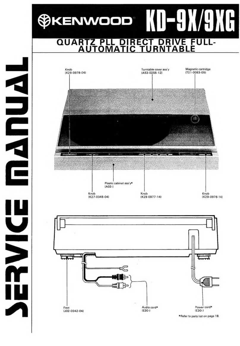
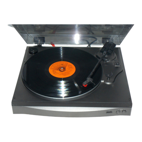
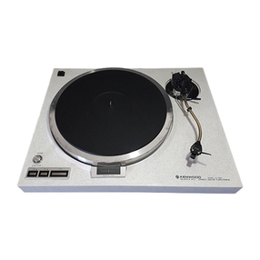
Kenwood KD-4020 User manual

GOO/ANADI
KD-4020
FULL
AUTOMATIC
TURNTABLE
INSTRUCTION
MANUAL
PLATINE
TOURNE-DISQUE
ENTIEREMENT
AUTOMATIQUE
MODE
D’EMPLO
VOLLAUTOMATISCHER
PLATTENSPIELER
BEDIENUNGSANLEITUNG
f
VOLAUTOMATISCHE
PLATENSPELER
GEBRUIKSAANWIJZING
GIRADISCHI
COMPLETAMENTE
AUTOMATICO
ISTRUZIONI
PER
L’USO
KENWOOD
CORPORATION
ONVITV
LI
B50-7831-08CKO>(E)(T)

ENGLISH
Introduction
Tf
A
a)
Your
choice
of
this
product
indicates
that
you
are
a
devotee
to
excellence
in
sound
reproduction.
We
appreciate
your
patronage
and
take
pride
in
the
long
tradi-
tion
of
quality
components
that
our
company
represents.
So
that
you
can
get
the
most
out
of
your
unit,
we
suggest
that
you
take
the
time
to
read
through
this
manual
before
you
hook
up
and
operate
your
system.
This
will
acquaint
you
with
oper-
ating
features
and
system-connection
considerations
so
that
your
listening
pleasure
will
be
enhanced
right
from
the
start.
You
will
notice
that
in
all
aspects
of
planning,
engineering,
styling,
operating
convenience
and
adaptability
we
have
sought
to
anticipate
your
needs
and
desires.
Keep
this
manual
handy
for
future
reference.
For
your
records
Record
the
serial
number,
found
on
the
back
of
the
unit,
in
the
spaces
designated
on
the
warranty
card,
and
in
the
space
provided
below.
Refer
to
the
model
and
serial
numbers
whenever
you
call
upon
your
dealer
for
information
or
service
on
this
product.
Model
Serial
Number
Unpacking
Unpack
the
unit
carefully
and
make
sure
that
all
accessories
are
put
aside
so
they
will
not
be
lost.
Examine
the
unit
for
any
possibility
of
shipping
damage.
If
your
unit
is
damaged
or
fails
to
operate,
notify
your
dealer
immedi-
ately.
lf
your
unit
was
shipped
to
you
directly,
notify
the
ship-
ping
company
without
delay.
Only
the
consignee
(the
person
or
company
receiving
the
unit)
can
file
a
claim
against
the
car-
rier
for
shipping
damage.
We
recommend
that
you
retain
the
original
carton
and
pack-
ing
materials
for
use
should
you
transport
or
ship
the
unit
in
the
future.
Contents
Caution:
Read
the
pages
marked
A
carefully
to
ensure
safe
operation.
ABefore
applying
POWEF
.............2..
cee
cece
eee
cee
eeeeeneeeeneeees
3
GOnneetionse
ci
cite
eaten
as
ieee
ob
etrstaetanes
8
ASafety
precautions
..........6...cceceeeee
eee
e
cette
ee ee
ee
eeeen
teeta
ee
3
Operating
instructions
.............
ccs
ence
eect
une
eeeene
es
9
AIMPORTANT
SAFEGUARDS
...........0..2.
0000
cece
cece
eee
eee
eens
4
Maintenance
.....................
PartS
NOMENCIHAtUIE
.....
2...
cece
eee
c
een
c
eee
ee
ee
eseeneneneeeceeneneees
6
In
case
of
difficulty
ASSEMMDIY
cashed
tens
ccevs
a
ndete
ver
SecteaiGtag
Deel oeee
aetna
toch
iaties
7
Specifications:
4.
1s
cies
eam
cde:
Roane
seen
2
«D-4020
(En)

A\Caution:
Read
this
page
carefully
to
ensure
safe
operation.
Before
applying
power
For
the
U.S.A.
and
Canada
Important!
For
Australia
and
Europe
Important!
|
Units
shipped
to
the
U.S.A.
and
Canada
are
designed
for
opera-
tion
on
120
volts
AC
only.
Safety
precaution
for
a
Polarized
AC
plug
However,
some
products
may
be
supplied
with
a
non-polarized
plug.
CAUTION:
To
PREVENT
ELECTRIC
SHOCK
DO
NOT
USE
THIS
(POLARIZED)
PLUG
WITH
AN
EXTENSION
CORD,
RECEPTACLE
OR
OTHER
OUTLET
UNLESS
THE
BLADES
CAN
BE
FULLY
INSERTED
TO
PREVENT
BLADE
EXPOSURE.
Units
shipped
to
Australia
are
designed
for
operation
on
240
V
AC
only.
Units
shipped
to
Europe
are
designed
for
operation
on
220
V
AC
only.
For
other
countries
For
the
United
Kingdom
important!
Units
shipped
to
the
U.K.
are
designed
for
operation
on
240
volts
AC
only.
The
mains
plug
must
be
removed
from
the
wall
socket
prior
to
any
internal
examination.
The
wires
in
this
mains
lead
are
coloured
in
accordance
with
the
following
code:
Bh
6s
55
fsa
Ste
he
keSvnbese
estates
ola
Neutral
BROWN
:isicilesd
hic,
srkereva
de
otnale
hater
nce
Live
The
wires
in
this
mains
lead
must
be
connected
to
the
termi-
nals
in
the
plug
as
follows:
Important!
Units
shipped
to
countries
other
than
the
above
countries
are
equipped
with
an
AC
voltage
selector
switch
under
the
turnta-
ble
platter.
Refer
to
the
following
paragraph
for
the
proper
set-
ting
of
this
switch.
AC
voltage
selection
This
unit
operates
on
110-120
or
220-240
volts
AC.
The
AC
voltage
selector
switch
under
the
turntable
platter
is
set
to
the
voltage
that
prevails
in
the
area
to
which
the
unit
is
shipped.
Before
connecting
the
power
cord
to
your
AC
outlet,
make
sure
that
the
setting
position
of
this
switch
matches
your
line
vol-
tage.
If
not,
it
must
be
set
to
your
voltage
in
accordance
with
the
following
direction.
Note:
Our
warranty
does
not
cover
damage
caused
by
excessive
line
voltage
due
to
improper
setting
of
the
AC
voltage
selector
switch.
Wire
colour
Plug
terminal
markin
F
BIB.
cine
tans
eden.
'N
oF
Black
:
phi
eal
BLOWN
stad
Svivedy
cestvinivcetinateens
L
or
Red
(>
Brown
to
uve
This
sh
itch
This
shi
itch
is
shows
switc
ts
shows
switc
cate
é
)
lever
is
locked
in
lever
is
locked
in
AC
110-120
V~
AC
220-240
V~
position.
position.
Plug
Notes:
1.
If
a
13-amp
plug
is
used,
this
must
be
fitted
with
a
5-amp
fuse.
2.
If
a
3-pin
plug
with
earthing
contact
is
used,
no
wire
must
be
connected
to
the
E
terminal.
Move
switch
lever
to
match
your
line
voltage
with
a
small
screwdriver
or
other
pointed
tool.
AC
voltage
selector
switch
Safety
precautions
WARNING:
TO
PREVENT
FIRE
OR
SHOCK
HAZARD,
DO
NOT
EXPOSE
THIS
APPLIANCE
TO
RAIN
OR
MOISTURE.
CAUTION
RISK
OF
ELECTRIC
SHOCK
DO
NOT
OPEN
CAUTION:
TO
REDUCE
THE
RISK
OF
ELECTRIC
SHOCK,
DO
NOT
REMOVE
COVER
(OR
BACK).
NO
USER-SERVICEABLE
PARTS
INSIDE,
REFER
SER-
VICING
TO
QUALIFIED
SERVICE
PERSONNEL.
THE
LIGHTNING
FLASH
WITH
ARROWHEAD
SYMBOL,
WITHIN
AN
EQUILATERAL
TRIANGLE,
IS
INTENDED
TO
ALERT
THE
USER
TO
THE
PRESENCE
OF
UNINSULATED
‘‘DANGEROUS
VOL-
TAGE”
WITHIN
THE
PRODUCT'S
ENCLOSURE
THAT
MAY
BE
OF
SUFFICIENT
MAGNITUDE
TO
CONSTITUTE
A
RISK
OF
ELECTRIC
SHOCK
TO
PERSONS.
THE
EXCLAMATION
POINT
WITHIN
AN
EQUILATERAL
TRIANGLE
IS
INTENDED
TO
ALERT
THE
USER
TO
THE
PRESENCE
OF
IMPORTANT
OPERATING
AND
MAINTENANCE
(SERVICING)
IN-
STRUCTIONS
IN
THE
LITERATURE
ACCOMPANYING
THE
APPLIANCE.
KD-4090
(Fn)
3
HSIONA

ENGLISH
A
Caution
:
Read
this
page
carefully
to
ensure
safe
operation.
IMPORTANT
SAFEGUARDS
Please
read
all
of
the
safety
and
operating
instructions
before
operating
this
unit.
For
best
results,
follow
all
warnings
placed
on
the
unit
and
adhere
to
the
operat-
ing
and
use
instructions.
These
safety
and
operating
in-
structions
should
be
retained
for
future
reference.
7.Heat
—
The
unit
should
be
situated
away
from
heat
sources
such
as
radiators,
heat
registers,
stoves,
or
other
units
(including
amplifiers)
that
produce
heat.
.
Power
sources
—
The
unit
should
be
connected
to
a
power
supply
only
of
the
type
described
in
the
operating
instructions
or
as
marked
on
the
appliance.
.
Power-cord
protection
—
Power-supply
cords
should
be
routed
so
that
they
are
not
likely
to
be
walked
on
or
pinched
by
items
placed
upon
or
against
them,
pay
particular
attention
to
cords
at
plugs,
convenience
receptacles,
and
the
point
where
they
exit
from
the
unit.
Never
pull
or
stretch
the
cord.
.
Electric
shock
—
Care
should
be
taken
so
that
ob-
jects
do
not
fall
and
liquid
is
not
spilled
into
the
en-
closure
through
openings.
If
a
metal
object,
such
as
a
hair
pin
or
a
needle,
comes
into
contact
with
the
inside
of
this
unit,
a
dangerous
electric
shock
may
result.
For
families
with
children,
never
permit
chil-
dren
to
put
anything,
especially
metal,
inside
this
unit.
3.Grounding
or
polarization
—
The
precautions
should
be
taken
so
that
the
grounding
or
polariza-
tion
means
of
this unit
is
not
defeated.
4.
Ventilation
—
The
unit
should
be
situated
so
that
9.Enclosure
removal
—
Never
remove
the
en-
its
location
or
position
does
not
interfere
with
its
proper
ventilation.
To
maintain
good
ventilation,
do
not
put
records
or
a
table-cloth
on
the
unit.
Place
the
unit
at
least
10
cm
away
from
the
walls.
Do
not
use
the
unit
on
a
bed,
sofa,
rug
or
similar
surface
that
may
block.
the
ventilation
openings.
closure.
If
the
internal
parts
are
touched
accidentally,
a
serious
electric
shock
might
occur.
10.
Magnetic
fields
—
Keep
the
unit
away
from
sources
of
magnetic
fields
such
as
TV
sets,
speaker
systems,
radios,
motorized
toys
or
magnetized
objects.
5.
Water
and
moisture
—
The
unit
should
not
be
used
near
water
—
for
example,
near
a
bathtub,
washbowl,
kitchen
sink,
laundry
tub,
in
a
wet
base-
ment,
or
near
a
swimming
pool,
etc.
11.
Cleaning
—
Do
not
use
volatile
solvents
such
as
alcohol,
paint
thinner,
gasoline,
or
benzine,
etc.
to
clean
the
cabinet.
Use
a
clean
dry
cloth.
6.
Temperature
—
The
unit
may
not
function
pro-
perly
if
used
at
extremely
low,
or
freezing
tempera-
tures.
The
ideal
ambient
temperature
is
above
+5°C
(41°F).
4
kp-4020
(En)

12.
Carts
and
stands
—
An
appliance
and
cart
com-
bination
should
be
moved
with
care.
Quick
stops,
excessive
force,
and
uneven
surfaces
may
cause
the
appliance
and
cart
combination
to
overturn.
A
——
13.Nonuse
periods
—
The
power
cord
of
the
unit
should
be
unplugged
from
the
outlet
when
left
un-
used
for
a
long
period
of
time.
14.
Abnormal
smell
—
If
an
abnormal
smell
or
smoke
is
detected,
immediately
turn
the
power
OFF
and
pull
out
the
power
cord.
Contact
your
dealer
or
nearest
service
center.
POWER
OFF!
15.
Damage
requiring
service
—
The
unit
should
be
serviced
by
qualified
service
personnel
when:
A.
The
power-supply
cord
or
the
plug
has
been
damaged;
or
B.
Objects
have
fallen,
or
liquid
has
been
spilled
into
the
unit;
or
C.
The
unit
has
been
exposed
to
rain;
or
D.
The
unit
does
not
appear
to
operate
normally
or
exhibits
a
marked
change
in
performance;
or
E.
The
unit
has
been
dropped,
or
the
enclosure
damaged.
16.
Servicing
—
The
user
should
not
attempt
to
ser-
vice
the
unit
beyond
that
described
in
the
operating
instructions.
All
other
servicing
should
be
referred
to
qualified
service
personnel.
17.
Outdoor
antenna
grounding
—
If
an
outside
an-
tenna
is
connected
to
the
receiver,
be
sure
the
an-
tenna
system
is
grounded
so
as
to
provide
some
protection
against
voltage
surges
and
built
up
static
charges.
Section
810
of
the
National
Electrical
Code,
ANSI/
NFPA
No.
70—1984,
provides
information
with
respect
to
proper
grounding
of
the
mast
and
supporting
structure,
grounding
of
the
lead-in
wire
to
an
antenna
discharge
unit,
size
of
grounding
con-
Notes:
A\
Caution
:
Read
this
page
carefully
to
ensure
safe
operation.
ductors,
location
of
antenna-discharge
unit,
connec-
tion
to
grounding
electrodes,
and
requirements
for
the
grounding
electrode.
See
Figure.
POWER
LINES
STANDOFF
b
INSULATORS:
SEAVICE
ENTRANCE
EQUIPMENT
~~~
ANTENNA
LEAD-IN
WIRE
ANTENNA
DISCHARGE
pete
TO
EXTERNAL
ANTENNA
POWER
SERVICE
GROUNDING
TERMINALS
OF
PRODUCT
ELECTRODE
SYSTEM
(e.g.
interior
metal
water
pipe)
BONDING
JUMPER?
GROUND
CLAMP
OPTIONAL
ANTENNA
GROUNDING
ELECTRODE
DRIVEN
8
FEET
(2.44
m)
INTO
THE
EARTH
IF
REQUIRED
BY
LOCAL
CODES.
SEE
NEC
SECTION
810-21{f).
FIGURE
EXAMPLE
OF
ANTENNA
GROUNDING
ACCORDING
TO
THE
NATIONAL
ELECTRICAL
CODE
INSTRUCTIONS
CONTAINED
IN
ARTICLE
810
—
“RADIO
AND
TELEVISION
EQUIPMENT”’
*
Use
No.
10
AWG
(5.3
mm?)
copper,
No.
8
AWG
(8.4
mm?)
aluminum,
No.
17
AWG
(1.0
mm?)
copper-clad
steel
or
bronze
wire,
or
larger,
as
a
ground
wire.
Secure
antenna
lead-in
and
ground
wires
to
house
with
stand-off
in-
sulators
spaced
from
4
—
6
feet
(1.22
—
1.83
m)
apart.
©
Mount
antenna
discharge
unit
as
close
as
possible
to
where
lead-in
enters
house.
4
Use
jumper
wire
not
smaller
than
No.
6
AWG
(13.3
mm*)
copper,
or
the
equivalent,
when
a
separate
antenna-grounding
electrode
is
used.
See
NEC
Section
810-21(j).
18.
Power
lines
—
An
outdoor
antenna
should
be
lo-
cated
away
from
power
lines.
1.
Item
3
is
not
required
except
for
grounded
or
polarized
equipment.
2.
Item
17
and
18
are
not
required
except
for
units
provided
with
antenna
terminalis.
3.
Item
17
complies
with
UL-1270
in
the
U.S.A.
HSISN3

ENGLISH
Parts
nomenclature
@
Check
that
the
packing
carton
contains
all
of
the
component
parts
@
See
page
7
for
assembly
procedures.
shown
in
the
figure
below
before
you
begin
to
assembie
the
turntable.
Dust
cover
Turntable
sheet
EP
adaptor
SS
Audio
cord
at
:
Ground
lead
Hinges
AC
cord
a
ta
SEN
Tonearm
Cartridge
EP
adaptor
stay
Turntable
platter
Center
spindle
POWER
switch
PLAY/CUT
key
SPEED
select
key
(33,
45)/indicators
CUEING
key
REPEAT
key/indicator
MANUAL
SEARCH
keys
(<,
>}

Assembly
@
Transport
tonearm
protection
screws
Remove
the
transport
tonearm
protection
screws
locat-
ed
on
the
bottom
of
the
unit.
Remove
the
transport
tonearm
protection
screws
(red)
using
a
screw
driver
etc.
After
removing,
keep
the
screws
for
future
moving.
Transport
tonearm
protection
screws
@
How
to
install
the
dust
cover
Zi
\
Dust
cover
®
Install
the
hinge
between
the
dust
cover
and
the
cabinet,
mak-
ing
sure
that
it
faces
in
the
correct
direction.
@
How
to
remove
the
spacers
and
set
the
turntable
sheet
HSITONZ
1
Remove
the
three
fixing
spacers.
f
@
Rotate
90°.
@
Remove.
2
Place
the
turntable
sheet
on
the
turntable
platter.
CESS
@
When
transporting
the
unit
again,
fix
the
spacers
in
reverse
way.
M@
How
to
remove
the
packing
and
sty-
lus
cover
Remove
the
packing
(holder)
of
the
tonearm,
and
pull
out
the
stylus
cover
in
the
direction
of
the
arrow.
Tonearm
Packing
Stylus
cover
vn
ananica,
7

Connections
ENGLISH
@
Connections
Turn
off
the
power
to
your
amplifier
or
receiver.
Con-
nect
the
audio
cord,
ground
lead,
system
control
cord,
then
the
AC
cord.
KD-4020
System
control
cord
Audio
cord
Ground
lead
SYSTEM
(CONTROL
Amplifier
or
receiver
KENWOOD
remo
wronsten
aman
ca
178
Cl)
Wa
To
AC
outlet
Setting
the
amplifier
This
unit
is
equipped
with
an
MM
cartridge.
Connect
the
audio
cord
of
this
unit
to
the
PHONO
MM
jacks
of
the
amplifier
or
set
the
cartridge
load
selector
of
the
amplifier
to
MM.
Notes:
1.
As
a
microcomputer
is
used
in
this
unit,
beat
noise
may
be
gener-
ated
when
receiving
broadcasts
with
the
tuner.
In
such
cases,
turn
off
the
power
switch
of
this
unit
or
adjust
the
tuner
antenna.
.
Incorrect
ground
lead
connection
may
sometimes
make
it
impos-
sible
to
activate
the
system
control
operation.
VIN
ANAA
Ir
System
control
connection
(Except
for
some
areas.)
When
connected
to
an
amplifier
or
receiver
having
KENWOOD
SYS-
TEM
CONTROL
terminals,
system
operation
such
as
remote
con-
trol
is
made
possible.
For
details,
refer
to
the
instruction
manual
of
the
amplifier
or
receiver.
If
your
amplifier
or
receiver
is
not
equipped
with
the
SYSTEM
CON-
TROL
Terminals,
do
not
connect
anything
to
any
SYSTEM
CON-
TROL
Terminal.
Do
not
connect
the
unit
in
any
system
configuration
other
than
specified.
@
Be
sure
to
insert
the
System
Control
cord
plugs
fully
into
the
SYSTEM
CONTROL
Terminals.
@
|f
the
system
contro!
cord
and
audio
cords
are
not
connected
properly,
the
automatic
system
governing
remote
control
and
system
functions
will
not
operate.

Operating
instructions
PLAY/CUT
key
SPEED
select
key
(33,
45)/indicators
REPEAT
key/indicator
@
Automatic
play
1
Turn
the
power
on
and
place
a
record
on
the
turntable
platter.
POWER
2
Press
the
PLAY/CUT
key.
PLAY/CUT
IJ
@
Playing
starts
from
the
beginning
of
the
record.
@
The
speed
is
automatically
set
to
33-1/3
rpm
for
30
cm
and
25
cm
records,
and
to
45
rpm
for
17
cm
records.
@
\f
30
cm
single
records
or
17
cm
LP
records
are
used,
set
the
SPEED
select
key
to
the
corresponding
position
after
the
tonearm
starts
the
auto-in
operation.
Cao
33
==
==
45.
————
———
Control
the
volume
with
the
VOLUME
con-
trol
on
the
amplifier.
@
At
the
end
of
the
record,
the
tonearm
returns
to
the
start
posi-
tion
and
the
turntable
platter
stops.
M@
To
repeatedly
play
a
record
Press
the
REPEAT
key.
(Repeated
play
is
only
possible
with
automatic
play.)
o——_—
=~
REPEAT
————————
=
@
This
repeats
the
record
a
maximum
of
16
times.
®
Press
again
to
release.
CUEING
key
@
To
stop
the
play
temporarily
Press
the
CUEING
key
to
momentarily
stop
playing.
The
tonearm
leaves
the
record.
CUEING
To
restart
playing,
press
the
CUEING
key
again.
The
record
play
resumes
almost
the
same
position.
@
To
stop
playback
operation
If
you
wish
to
stop
play
operation
part
way
through
a
record,
press
the
PLAY/CUT
key.
The
tonearm
will
au-
tomatically
return
to
the
start
position,
and
the
turnta-
ble
platter
will
stop
turning.
PLAY/CUT
lj
MANUAL
SEARCH
keys
(<4,
>)
When
playing
a
17
cm
(7
inch)
record...
Use
the
EP
adapter.
Note:
With
this
unit,
the
record
size
is
automatically
detected
using
an
opti-
cal
device.
However,
if
the
following
records
are
used,
automatic
record
size
detection
may
not
function
correctly.
In
such
cases,
play
the
records
manually.
®
Scratched
records
®
Records
with
a
narrow
groove
guard
®@
Records
having
a
surface
with
excessively
low
reflection
HSITSNA

Operating
instructions
PLAY/CUT
key
SPEED
select
key
(33,
45}/indicators
CUEING
key
REPEAT
key/indicator
MANUAL
SEARCH
keys
(4,
>}
@
Manual
play
@
To
stop
the
play
temporarily
Turn
the
power
on
and
set
a
record
on
the
turntable
platter.
Press
the
CUEING
key
to
momentarily
stop
playing.
The
tonearm
leaves
the
record.
CUEING
Advance
the
tonearm
to
the
selected
position
using
MANUAL
SEARCH
(4)
key.
To
restart
playing,
press
the
CUEING
key
again.
The
MANUAL
SEARCH
record
play
resumes
almost
the
same
position.
|
es
|
@
MANUAL
SEARCH
(<4)
key
advances
the
tonearm
to
the
left,
and
the
MANUAL
SEARCH
(&)
key
advances
the
tonearm
to
|
Ill
To
stop
playback
operation
the
right.
If
you
wish
to
stop
play
operation
part
way
through
a
record,
press
the
PLAY/CUT
key.
The
tonearm
will
au-
tomatically
return
to
the
start
position,
and
the
turnta-
ble
platter
will
stop
turning.
3
Select
the
SPEED
select
key
according
to
the
record.
PLAY/CUT
lI
4.
Press
the
CUEING
key.
CUEING
®@
This
lowers
the
stylus
to
the
record
and
playing
starts.
Control
the
volume
with
the
VOLUME
con-
trol
on
the
amplifier.
Note:
Record
play
cannot
be
started
within
a
radial
distance
of
63
mm
{2-1/2”)
from
the
center
of
the
record.
®
At
the
end
of
the
record,
the
tonearm
returns
to
the
start
posi-
When
the
tonearm
reaches
the
innermost
groove
of
the
record,
pressing
tion
and
the
turntable
platter
stops.
the
CUEING
switch
will
return
the
tonearm
to
the
start
position
auto-
matically.
aM
on
wk

Maintenance
Caen
SSS
a
I
ARTES
PE
@
Stylus
replacement
A
replacement
stylus
can
be
obtained
from
your
dealer.
1
Set
the
POWER
switch
of
the
amplifier
and
turntable
to
OFF.
Pull
out
the
stylus
in
the
direction
of
the
ar-
row
shown
in
the
figure.
Removing
the
stylus
Motor
lubrication
The
built-in
motor
does
not
require
lubrication.
Periodic
check-up
Because
a
turntable
is
a
mechanical
device,
it
is
subject
to
the
ef-
fects
of
wear
and
misadjustment
that
occur
during
normal
han-
dling
and
operation.
Even
if
your
unit
appears
to
function
normally,
a
periodic
check-up
at
intervals
of
two
years
or
so
is
recommend-
ed
to
ensure
a
long
service
life
and
proper
operation.
Check
with
your
dealer
or
authorized
service
representative.
2
Replace
with
a
new
stylus
KENWOOD
speci-
fied
(N-75)
in
the
reverse
order
of
step
1
Installing
the
stylus
@
When
replacing
the
stylus,
take
care
not
to
damage
the
stylus
tip.
Note:
The
unit's
power
supply
is
secondarily
connected.
Note
following
.
The
unit
is
not
completely
disconnected
from
the
mains
as
long
as
the
power
cord
is
connected
to
a
wall
outlet.
Observera:
Apparatens
stromfdérsdérjning
kopplas
fran
sekundart.
V.g.
ge
akt
pa
foljande.
Apparaten
frankopplas
inte
helt
och
hallet
fran
strémnatet
medan
apparatens
natsladd
ar
ansluten
till
vaxelstrémsuttaget.
Huom:
Virta
yksikké6n
on
kytketty
pois
sekundaaripuolelta.
Huomioi
seuraava.
Tamé
yksikké
ei
ole
kokonaan
kypketty
pois
paa
Virranjakajasta
kun
paa
katkaisin
on
liitettyna
virtatiiriin.
Bemeerk:
Stremmen
til
apparatet
aforydes
p&
den
sekundaere
side.
Vear
op-
meerksom
pa
felgende.
Denne
enhed
er
ikke
fulistendig
koblet
fra
lysnettet
sA
lenge
stik-
ket
er
tilsluttet
stikkontakten.
Anmerkning:
Strammen
til
apparatet
er
slatt
av
pA
sekundzersiden.
Vaer
oppmerk-
som
pa
det
falgende.
Dette
apparatet
koples
ikke
fullstendig
fra
nettet
s&
lenge
stapse-
let
star
i
en
stikkontakt,
selv
om
strambryteren
settes
i
av-stilling.
UR
AnAA
Ie
8
HSIMONI

In
case
of
difficulty
What
appears
to
be
a
malfunction
may
not
always
be
serious.
If
your
unit
should
not
perform
as
expected,
consult
the
table
below
to
see
if
the
problem
can
be
corrected
before
seeking
help
from
your
dealer
or
service
representative.
Symptom
Cause
Correction
—
No
sound
from
both
left
and
right
chan-
nels
or
from
one
channel.
Turntable
output
cable(s)
disconnected.
The
function
switch
of
the
amplifier
is
not
set
to
PHONO.
Check
connections
to
amplifier.
Set
the
function
switch
to
PHONO.
Loud
hum,
no
music.
Poor
connection
of
turntable
output
cables.
Loud
hum
with
music.
Turntable
output
cables
picking
up
hum
from
AC
cord.
The
ground
lead
of
the
turntable
is
not
con-
nected
to
the
GND
terminal
of
the
am-
plifier.
Make
solid
connections
to
amplifier.
Separate
output
cables
from
AC
cord
or:
reverse
AC
cord
plug.
Connect
the
ground
lead
to
the
GND
ter-
minal
of
the
amplifier.
Buzzing
noise
with
music.
Turntable
output
cables
picking
up
TV
signal.
Relocate
output
cables
for
minimum
pickup.
Howling
drowns
out
music
when
volume
is
increased.
Speaker
vibration
is
picked
up
by
turntable.
Separate
turntable
from
speakers.
Turntable
platter
does
not
turn.
Poor
AC
plug
contact.
Check
connection.
Make
sure
AC
outlet
is
active.
Poor
tracking.
Excessive
dust
on
record
or
stylus.
Remove
dust
from
record
or
stylus.
Tonearm
does
not
move.
Notes:
The
transport
tonearm
protection
screws
have
not
been
removed.
1.
As
this
system
uses
microprocessors,
it
may
not
function
properly
due
to
external
noise
or
interference
noise.
If
this
happens,
disconnect
the
power
plug
from
the
outlet,
wait
several
seconds,
then
reconnect.
2.
Do
not
use
contact
cleaner
because
it
could
cause
a
malfunction.
Be
specially
careful
against
contact
cleaners
containing
oil,
for
they
may
deform
the
plastic
components.
Specifications
Motor
and
Turntable
Drive
System
brushless
motor
Turntable
Platter
..............
29.6
cm
diameter
0.34
kg
weight
Cartridge
Direct-drive
system
TYPO?
viesceeebecsietise
Motor
..............cc
cece
ee
eee
ee
20-pole,
30-slot,
3-phase
Output
Voltage
Frequency
Response
Channel
Separation
Remove
both
of
the
two
transport
tonearm
protection
screws.
sengagsyeeis
VM
cartridge
(V-75)
scvat
obes
20
~
20,000
Hz
pete
Better
than
20 dB
(1,000
Hz)
Speeds
....................:0e
2
speeds,
33-1/3
and
45
rpm
Load
Impedance...............
47
kQ
Wow
&
Flutter.................
0.06%
(WRMS)
Styl
cis
seceeien
Maas
N-75
with
0.6
mil
diamond
S/N
(Rumble)...................
DIN:
68
dB
(Weighted)
Optimum
Tracking
Force
...2.5
g
Compliance
.....................
4x
10°°
emidyne
Tonearm
TY
DOs.2i0ietesc
Raced
thes
Linear
Tracking
Tonearm
Miscellaneous
Power
Consumption
.........
12
W
Dimensions......................
W:
440
mm
H:
109
mm
D:
346
mm
Weight
(Net)....................
3.9
kg
Note:
KENWOOD
follows
a
policy
of
continuous
advancements
in
development.
For
this
reason
specifications
may
be
changed
without
notice.
12.
kn-a020
ten
i
i

KENWOOD

Introduction
a
a
a a
a
I
Votre
choix
sur
ce
produit
prouve
que
vous
étes
exigeant
en
matiére
de
reproduction
sonore.
Nous
vous
remercions
de
ce
choix
et
sommes
fiers
de
la
lon-
gue
tradition
d’éléments
de
qualité
qui
sont
le
reflet
de
notre
société.
Pour
obtenir
le
meilleur
de
votre
appareil,
nous
vous
suggé-
rons
de
prendre
le
temps
de
lire
attentivement
ce
manuel
avant
de
monter
et
de
faire
fonctionner
votre
appareil.
Ceci
vous
fami-
liarisera
avec
les
caractéristiques
de
son
fonctionnement
ainsi
qu’avec
les
raccordements
du
systéme
pour
que
votre
plaisir
d'écoute
soit
maximal
depuis
le
début.
Vous
remarquerez
que
dans
les
domaines
du
planning,
de
|'ingéniérie,
de
la
stylique,
de
la
commodité
du
fonctionnement
et
de
!’adaptabilité,
nous
avons
devancé
vos
besoins
et
désirs.
Gardez
ce
manuel
pour
une
référence
future.
Pour
votre
référence
Inscrivez
le
numéro
de
série,
que
vous
trouverez
a
l’arriére
de
l'appareil,
dans
les
espaces
prévus
de
la
carte
de
garantie
et
dans
l’espace
prévu
ci-dessous.
Indiquez
les
numéros
de
modale
et
de
série
au
cas
ou
vous
devrez
faire
appel
a
votre
concessionnaire
pour
des
renseignements
ou
réparations
de
cet
appareil.
Modéle
_____-————S—
Numéro
de
série
Déballage
Déballez
soigneusement
|‘appareil
et
assurez-vous
de
mettre
de
cété
tous
les
accessoires
de
maniére
4
ne
pas
les
perdre.
Examinez
bien
l'appareil
pour
déceler
d’éventuels
endomma-
gements
pendant
le
transport.
Si
votre
appareil
est
endommagé
ou
s’il
ne
fonctionne
pas,
en
aviser
immédiatement
votre
con-
cessionnaire.
Si
votre
appareil
vous
a
été
livré
directement,
avertir
immédiatement
la
société
de
transport.
Seule
la
per-
sonne
ou
la
société
ayant
recu
l’appareil
peut
porter
plainte
contre
le
transporteur
en
cas
d’endommagement.
Nous
vous
recommandons
de
garder
le
carton
et
le
matériel
d’emballage
d‘origine
au
cas
o&
vous
auriez
a
transporter
ou
a
envoyer
votre
appareil
dans
l'avenir.
Sommaire
Attention
:
Lire
les
pages
marquées
A
avec
attention
pour
garantir
un
fonctionnement
en
toute
sécurité.
AAvant
la
mise
Sous
teNnSiON
.............
22.
eeeeeeeee
ners
seer
eee
ees
16
Branchements
ies.
cuscs
castes
the
Rac
diate
dead
hecaeaus
tage
APrécautions
de
S@CUFItE.....
0...
cece
cece
cece
eee
ee
nee
eeeeeneseeeee
15
Manipulation...
vesscesccscesstaveriesvesbys
cenetiiveeawesant
svendse
ees
APRECAUTIONS
IMPORTANTES
DE
SECURITE...............-
16
Enitvetion:
23420224:
Ligiage
meats
segs
Nomenclature
des
pieces
.............ccc
cece
see
eneeeeeee
eee
een
nee
18
En
cas
de
difficulté
ASSEMbIEQE
sec.
.c
ces
As
ed
cecteeetethe
pe
ceecreee
tees
rete
19
Caractéristiques
1.08.
cccessa,
dsecd
sede
eee
saieegee
cieeetan
daeeensen
es’

A
Attention:
Lire
attentivement
cette
page
pour
Avant
la
mise
sous
tension
Pour
les
Etats-Unis
et
le
Canada
garantir
une
exploitation
sans
danger.
imi
a
Eee
eg
Te]
Pour
I’Europe
Important!
Les
appareils
exportés
vers
les
Etats-Unis
et
le
Canada
sont
con-
¢us
pour
une
alimentation
sur
secteur
de
120
volts
exclusi-
vement.
Précaution
de
sécurité
pour
une
prise
secteur
polarisée
Toutefois,
certains
appareils
sont
pourvus
d'une
fiche
non
polarisée.
ATTENTION:
pour
PREVENIR
LES
CHOCS
ELECTRI-
QUES
NE
PAS
UTILISER
CETTE
FICHE
POLARISEE
AVEC
UN
PROLONGATEUR,
UNE
PRISE
DE
COURANT
OU
UNE
AUTRE
SORTIE
DE
COURANT,
SAUF
SI
LES
LAMES
PEUVENT
ETRE
INSEREES
A
FOND
SANS
EN
LAISSER
AUCUNE
PARTIE
A
DECOUVERT.
Important!
Les
appareils
expédiés
vers
|’Australie
sont
destinés
a
une
ali-
mentation
sur
secteur
de
240
V
uniquement.
Les
appareils
expédiés
vers
I'Europe
sont
destinés
a
une
ali-
mentation
sur
secteur
de
220
V
uniquement.
Pour
les
autres
pays
Pour
le
Royaume-Uni
important!
Les
appareils
expédiés
vers
le
Royaume-Uni
sont
destinés
4
une
alimentation
sur
secteur
de
240
V
uniquement.
La
fiche
secteur
doit
étre
débranchée
de
la
prise
secteur
avant
tout
examen
de
!’appareil.
Les
fils
du
cordon
secteur
sont
colorés
selon
fe
code
suivant:
BIBU:.
atin
cette
oOo
Por.
decdet
tenet
Neutre
BrUlieeds
soon
bnteacsean
shodonccresvetese
sds
Sous
tension
Les
fils
de
ce
cordon
secteur
doivent
étre
raccordés
comme
suit
sur
les
bornes
de
la
fiche:
Couleur
de
fil
Repére
sur
la
borne
BOW
22.02.
drevsocivactvatees
Sedgtesnats
N
ou
noir
BrUMcssaitedirncs
tiwietieeseveerdest
hate
L
ou
rouge
Brun
sous
S}
tension
Bleu
au
neutre
wv)
Fiche
Remarques:
1.
Si
une
fiche
de
13
ampéres
est
utilisée,
elle
doit
étre
pour-
vue
d’‘un
fisible
de
5
ampéres.
2.
Si
une
fiche
4
3
broches
avec
contact
de
masse
est
utili-
sée,
aucun
fil
ne
peut
étre
raccordé
a
la
borne
E.
Précautions
de
sécurité
AVERTISSEMENT:
POUR
EVITER
TOUT
INCENDIE
OU
CHOC
ELECTRIQUE,
NE
PAS
EXPO-
Important!
Les
appareils
exportés
vers
les
pays
autres
que
ceux
mention-
nés
ci-avant
sont
munis
d‘un
sélecteur
de
tension
secteur
sous
le
plateau
de
la
platine.
Se
référer
au
paragraphe
suivant
pour
ajuster
correctement
ce
sélecteur.
Sélection
de
la
tension
du
secteur
Cet
appareil
peut
s’alimenter
sur
secteur
de
110-120
ou
220-240
volts.
Le
sélecteur
de
tension,
implanté
sous
le
pla-
teau
de
la
platine,
a
été
régié
en
fonction
de
la
tention
en
vigueur
dans
la
région
de
destination.
Avant
de
brancher
la
fiche
du
cordon
d’alimentation
sur
une
prise
du
secteur,
priére
de
con-
firmer
que
la
position
de
réglage
de
ce
sélecteur
convient
a
la
tension
de
la
région.
Dans
la
négative,
il
doit
tre
ajusté
en
pro-
cédant
comme
suit.
Remarque:
Notre
garantie
ne
couvre
pas
les
dégats
occasionnés
par
une
tension
excessive,
résultant
d’un
réglage
inadéquat
du
sélec-
teur
de
tension
secteur.
110V—
'220v—
120V
iaaev
|
Ceci
indique
que
le
levier
du
sélecteur
est
bloqué
a
la
posi-
tion
110-120
V~
Ceci
indique
que
le
levier
du
sélecteur
est
bloqué
a
la
posi-
tion
220-240
V~
A
l'aide
d'un
tournevis
ou
d’un
objet
pointu,
dépla-
cer
le
levier
du
sélecteur
pour
convenir
a
la
ten-
sion
de
sa
région.
Commutateur
de
tension
SIVONVH4
SER
CET
APPAREIL
A
LA
PLUIE
OU
A
L’HUMIDITE.
ATTENTION:
POUR
REDUIRE
LES
RISQUES
DE
CHOC
ELECTRIQUE,
NE
PAS
ATTENTION
DEPOSER
LE
COUVERCLE
(OU
LE
PANNEAU
ARRIERE).
ANCUNE
PIECE
RISQUE
DE
CHOC
ELECTRIQUE
REPARABLE
PAR
L'UTILISATEUR
NE
SE
TROUVE
A
L’INTERIEUR.
CONFIER
NE
PAS
OUVRIR
TOUT
TRAVAIL
D’ENTRETIEN
A
UN
PERSONNEL
DE
SERVICE
QUALIFIE.
LE
SYMBOLE
DE
L’ECLAIR
DANS
UN
TRIANGLE
EQUILATERAL
A
POUR
BUT
D’ATTIRER
L'ATTENTION
DE
L’UTILISATION
SUR
LA
PRESENCE,
A
L’INTERIEUR
DU
COFFRET,
D’UNE
TENSION
DANGEREUSE
ET
NON
ISOLEE
D’UNE
PUISSANCE
SUFFISANTE
POUR
CONSTITUER
UN
RISQUE
DE
COMMOTION
ELECTRIQUE
AUX
ETRES
HUMAINS.
~
A
L'ENTRETIEN.
LE
POINT
D’EXCLAMATION
DANS
UN
TRIANGLE
EQUILATERAL
A
POUR
BUT
D’ATTIRER
L'ATTENTION
DE
L’UTILISATEUR
SUR
LA
PRESENCE,
DANS
LA
LITTERATURE
QUI
ACCOM-
PAGNE
CET
APPAREIL,
D‘INFORMATIONS
IMPORTANTES
RELATIVE
A
L'EXPLOITATION
ET

PRECAUTIONS
IMPORTANTES
DE
SECURITE
A\
Attention:
Lire
attentivement
cette
page
pour
garantir
une
exploitation
sans
danger.
Veuillez
lire
toutes
les
instructions
concernant
la
sécurité
et le
fonctionnement
avant
de
faire
fonctionner
cet
appareil.
Pour
les
meilleurs
résultats
possibles,
suivre
tous
les
avertissements
placés
sur
|‘appareil
et
les
instructions
de
fonctionnement
et
d'utilisation.
Ces
instructions
concernant
la
sécurité
et
le
fonc-
tionnement
doivent
étre
gardées
pour
une
référence
future.
1.
Sources
d’alimentation
—
Cet
appareil
doit
étre
raccordé
4
une
alimentation
du
type
décrit
dans
les
instructions
de
fonctionnement
ou
inscrit
sur
|’appareil.
2.
Protection
du
cordon
d’alimentation
—
Les
cordons
d’alimentation
doivent
étre
placés
de
maniére
qu’ils
ne
soient
pas
piétinés
ou
écrasés;
attention
en
particulier
aux
cordons
prés
des
prises
ou
réceptacles
et
au
point
ou
ils
sortent
de
l'appareil.
Ne
jamais
tirer
sur
Je
cordon.
3.
Mise
a
la
masse
ou
polarisation
—
Veiller
4
ne
pas
ren-
dre
nulle
l’efficacité
de
la
mise
a
la
masse
et
de
la
polari-
sation
de
cet
appareil.
4.
Aération
—
L’appareil
doit
6tre
positionné
de
maniére
a
ne
pas
géner
son
aération.
Pour
garantir.une
bonne
aération,
ne
pas
placer.dessus
des
disques
ni
un
tapis
de
table.
Placer
l'appareil
a
au
moins
10
cm
des
murs.
Ne
pas
utiliser
|‘appareil
sur
un
lit,
un
divan,
un
tapis
ou
autre
surface
similaire
qui
risque
de
bloquer
les
orifices
d’aération.
5.
Eau
et
humidité
—
L’appareil
ne
doit
pas
étre
utilisé
prés
de
l'eau,
par
exemple,
prés
d’une
baignoire,
d'une
cuvette,
d'un
évier,
d’une
bassine,
dans
un
sous-sol
mouillé
ni
prés
d'une
piscine,
etc.
6.
Température
—
Cet
appareil
risque
de
ne
pas
bien
fonc-
tionner
s'il
est
utilisé
4
des
températures
extrémement
bas-
ses,
La
température
ambiante
idéale
est
de
plus
de
+
5°.
an
7.
Chaleur
—
Cet
appareil
doit
étre
tenu
a
|’écart
de
sour-
ces
de
chaleur
comme
des
radiateurs,
des
trappes
de
cha-
leur,
des
poéles
et
autres
appareils
(y
compris
des
amplificateurs).
8.
Chocs
électriques
—
Un
soin
particulier
doit
étre
pris
pour
qu’aucun
objet
ne
pénétre
dans
l'appareil
et
qu’aucun
liquide
ne
soit
renversé
dessus.
Si
un
objet
métallique
comme
une
épingle
a
cheveux
ou
une
aiguille
entre
en
contact
avec
|’intérieur
de
cet
appareil,
un
choc
électri-
que
dangereux
risque
d’en
résulter.
Si
vous
avez
des
enfants,
ne
leur
permettez
jamais
d‘introduire
quoi
que
ce
soit,
en
particulier
des
objets
métalliques,
dans
cet
appareil.
9.
Retrait
du
coffret
—
Ne
jamais
retirer
le
coffret.
Si
les
pié-
ces
internes
sont
accidentellement
touchées,
un
choc
élec-
trique
sérieux
risque
de
se
produire.
10.
Champ
magnétique
—
Tenir
{l'appareil
a
|’écart
d'une
source
de
magnétisme,
telle
que
des
téléviseurs,
haut-
parleurs,
radios,
jouets
motorisés
ou
objets
magnétisés.
11.
Nettoyage
—
Ne
pas
utiliser
de
solvants
volatiles
tels
que
de
|’alcool,
du
diluant
a
peinture,
de
l’essence
ou
de
la
benzine,
etc.,
pour
nettoyer
le
coffret.
Utiliser
un
chiffon
propre
et
sec.

12.
Transport
et
supports
—
Si
l'appareil
est
placé
sur
un
13.
14
15.
16.
17.
Remarques:
support
mobile,
le
déplacer
avec
soin.
Les
arréts
brusques,
contraintes
ou
irrégularités
du
plancher
par
exemple
pour-
raient
provoquer
une
chute
de
l'appareil.
LAr
Inutilisation
—
Le
cordon
d’alimentation
de
|'appareil
doit
étre
débranché
de
la
prise
dans
le
cas
ot
il
ne
sera
pas
utilisé
pendant
longtemps.
Odeur
anormale
—
Si
une
odeur
anormale
ou
une
fumée
sortent
de
l'appareil,
couper
immédiatement
|’alimenta-
tion
et
débrancher
le
cordon
d‘alimentation.
Contacter
un
concessionnaire
ou un
centre
de
service
le
plus
proche.
COUPER
L’ALIMENTATION
!
Endommagement
demandant
réparation
—
L’appareil
doit
étre
réparé
par
un
technicien
qualifié
dans
les
cas
suivants:
A.
Dégats
subits
par
le
cordon
d’alimentation
secteur
ou
sa
fiche.
B.
Pénétration
d’un
solide
ou
d’un
liquide
dans
le
coffret.
C.
Exposition
de
|’appareil
a
fa
pluie.
D.
Fonctionnement
anormal
ou
changement
notoire
des
performances.
E.
Chute
de
l'appareil
ou
dég&ts
subits
par
le
coffret.
Entretien
—
L’utilisateur
ne
doit
pas
donner
d’autres
soins
que
ceux
décrits
dans
le
mode
d'emploi.
Toute
répara-
tion
doit
étre
confiée
a
un
personnel
d’entretien
qualifié.
Mise
a
Ia
terre
de
l’antenne
extérieure
—
Si
une
antenne
extérieure
est
raccordée
a
l'appareil,
elle
doit
&tre
mise
a
la
terre
pour
assurer
une
protection
contre
les
sautes
de
tension
et
les
charges
d’électricité
statique.
La
section
810
du
Code
national
sur
I’électricité
ANSI/NFPA
N°
70-1984
fournit
des
informations
sur
la
mise
a
la
terre
du
mat
et
de
la
structure
de
soutien
de
|’antenne,
mise
a
la
terre
du
conducteur
au
paratonnerre
d’antenne,
dimen-
sions
des
conducteurs
de
mise
a
la
terre,
emplacement
du
paratonnerre,
connexion
des
électrodes
de
mise
a
la
terre
et
autres
informations.
Voir
la
Figure.
18
A\
Attention:
Lire
attentivement_
cette
page
pour
garantir
une
exploitation
sans
danger.
Lignes
électriques
Colonnes
isolantes
*
Mat
Equipement
d’entrée
de
figne
Conducteur
d’antenne
Paratonnerre
d’antenne
*
Aux
bornes
d‘antenne
Systéme
a
électrode
de
terre
de
ligne
extérigure
de
l'appareil
électrique
Cavalier
de
mise
&
la
masse
*
Attaches
de
terre
Electrode
en
option
pour
mise
&
la
terre
d’antenne
enfouie
&
8
pieds
(2,44
m}
sous
terre
si
exigé
par
los
raglements
locaux.
Voir
NEC
Section
810-21{f).
Figure
Exemple
de
mise
a
la
terre
d'une
antenne
conformément
aux
instructions
du
code
national
sur
I’électricité,
article
810
‘‘Equipement
de
radio
et
téiévision’’
SIVONVYS
*Comme
fil
de
mise
&
la
terre,
utiliser
un
fil
de
cuivre
N°
10
AWG
(5,3
mm?),
d'aluminium
N°
8
AWG
(8,4
mm?),
d’acier
enrobé
de
cui-
vre
N°
17
AWG
(1,0
mm?)
ou
de
bronze
au
minimum.
”
Fixer
le
conducteur
d’antenne
et
les
fils
de
mise
a
la
terre
sur
I'immeuble
a
l'aide
de
colonnes
isolantes,
espacées
de
1,22
4
1,83
m.
°
Installer
le
paratonnerre
d’antenne
aussi
prés
que
possible
du
point
d’entrée
du
conducteur
dans
|'immeuble.
4Comme
cavalier,
utiliser
un
fil
de
cuivre
supérieur
au
N°
6
AWG
(13,3
mm?)
ou
équivalent
quand
est
utilisée
une
électrode
d’antenne-
terre
séparée.
Voir
NEC
Section
810-21(j).
Lignes
électriques
—
Une
antenne
extérieure
doit
étre
ins-
tallée
a
l’écart
de
lignes
électriques.
1.
L’article
3
n’est
pas
requis
sauf
pour
un
équipement
mis
a
la
terre
ou
polarisé.
2.
Les
articles
17
et
18
ne
sont
pas
requis,
sauf
pour
les
appareils
munis
de
bornes
d’antenne.
3.
L’article
17
est
conforme
au
raglement
UL-1270
aux
Etats-Unis.

Nomenclature
des
pieces
SA
a
a
TE
@
Vérifier
avant
de
commencer
le
montage
que
|’emballage
®
Voir
page
19
pour
la
procédure
de
montage.
contient
toutes
les
piéces
indiquées
sur
la
figure
ci-dessous.
Couvercle
anti-poussiére
——__—_—_____———
Tapis
de
la
platine
Adaptateur
45t
+
=}
Cable
audio
——{
Fil
de
masse
Charniére
Vers
una
prise
CA
Bras
de
lecture
Cellule
Adaptateur
longue
durée
Plateau
de
la
platine
Axe
central
Interrupteur
d’alimentation
(POWER)
Touch
de
lecture/interruption
(PLAY/CUT)
Sélecteur
de
vitesse
(SPEED)
(33,
45}/
Touch
de
repérage
Indicateur
de
vitesse
(CUEING)
Touch
de
répétition
(REPEAT)/
Touches
de
recherche
manueltle
Indicateur
de
répétition
(MANUAL
SEARCH
<,
>)

Assemblage
li
Vis
de
protection
du
bras
acoustique
Déposer
les
vis
de
protection
du
bras
acoustique,
pré-
vues
sur
le
fond
de
Il’appareil.
Déposer
les
vis
(rouge)
a
l'aide
d’un
tournevis.
Aprés
la
dépose,
conserver
les
vis
en
vue
d'une
éven-
tuelle
utilisation
ultérieure.
Vis
de
protection
du
bras
acoustique
M
Installation
du
couvercle
anti-
poussiére
Couvercle
anti-poussiére
@
Installer
la
charniére
entre
le
capot
et
le
coffret
de
la
platine-
disque
en
veillant
a
!’orienter
dans
la
bonne
direction.
M@
Dépose
des
entretoises
et
tapis
du
plateau
pose
du
1
Enlever
les
trois
entretoises
de
fixation.
r
@
Tourner
de
90°.
@
Enlever.
t
De
la
méme
maniére,
déposer
les
trois
entretoises.
2
Poser
le
tapis
sur
le
plateau
du
tourne-disque.
CES
@
Avant
de
transporter
l’appareil,
replacer
les
entretoises
en
sui-
vant
l’ordre
inverse.
@
Dépose
de
la
protection
et
du
capu-
chon
de
la
pointe
de
lecture
Déposer
la
protection
(support)
du
bras
acoustique
et
reti-
rer
le
capuchon
de
fa
pointe
de
lecture
cans
le
sens
de
la
fléche.
Bras
de
lecture
Rondelle
ynananics
$0

Branchements
@
Connexions
Couper
I’alimentation
de
l’amplificateur
ou
de
l’ampili-
tuner.
Brancher
le
cordon
audio,
le
fil
de
mise
4
Ia
terre,
le
cordon
de
contréle
systématisé
et
enfin
le
cordon
d’ali-
mentation.
KD-4020
Cable
de
contréle
du
systéme
Cable
audio
Vers
la
prise
Fil
de
masse
SYSTEM
(CONTROL
KENWOOD
stemo
areenarib
ssaruram
1
138
Réglage
de
l’amplificateur
Cet
appareil
est
équipé
d’une
cellule
4
aimant
mobile
(MM).
Bran-
cher
fe
cordon
audio
de
cet
appareil
sur
les
prises
PHONO
MM
de
l‘amplificateur
ou
régler
le
sélecteur
de
charge
de
cellule
de
!’ampli-
ficateur
sur
MM.
Remarques:
1,
Comme
un
micro-ordinateur
est
incorporé
a
cet
appareil,
il
se
peut
qu’un
bruit
de
battement
soit
provoqué
lors
de
la
réception
d’émis-
sions
radio
par
le
tuner.
Dans
ce
cas,
mettre
cet
appareil
hors
ten-
sion
ou
ajuster
l'antenne
du
tuner.
2.
Un
raccordement
incorrect
du
fil
de
mise
a
la
terre
peut
parfois
rendre
impossible
le
fonctionnement
de
controle
du
systéme.
an
KD.ANIN
(FY
Branchement
pour
contréle
systématisé
(Sauf
dans
certaines
régions)
Lorsque
la
platine
est
raccordée
4
un
amplificateur
ou
a
un
ampli-
tuner,
doté
de
bornes
SYSTEM
CONTROL
KENWOOD,
un
fonc-
tionnement
systématisé,
tel
que
le
contrdle
a
distance,
est
possi-
ble.
Pour
les
détails,
consulter
le
mode
d'emploi
de
|’amplificateur
ou
de
|’ampli-tuner.
Si
l’'amplificateur
ou
|’‘ampli-tuner
n’est
pas
muni
de
bornes
SYSTEM
CONTROL,
ne
rien
brancher
sur
la
borne
SYSTEM
CONTROL.
Ne
pas
raccorder
|’appareil
selon
une
configuration
autre
que
celle
qui
est
spécifiée.
J.
is,
®@
Veiller
&
insérer
&
fond
les
fiches
SYSTEM
CONTROL
sur
les
bornes.
@
Si
le
cable
du
systéme
et
les
cAbles
audio
ne
sont
pas
connec-
tés
correctement,
le
systeme
automatique
contrdlant
les
fonc-
tions
de
télécommande
et
du
systéme
ne
fonctionneront
pas
correctement.
een
es
ween
Table of contents
Languages:
Other Kenwood Turntable manuals

Kenwood
Kenwood P-T400 User manual

Kenwood
Kenwood KD-4100 User manual

Kenwood
Kenwood KD-492F User manual

Kenwood
Kenwood P-110 User manual

Kenwood
Kenwood KD-2055 User manual

Kenwood
Kenwood KD-2077 User manual

Kenwood
Kenwood KD-850 User manual

Kenwood
Kenwood KD-291R User manual

Kenwood
Kenwood KD-3070 User manual

Kenwood
Kenwood P-T400 User manual

Kenwood
Kenwood KD-291R User manual

Kenwood
Kenwood P-66 User manual

Kenwood
Kenwood KD-600 User manual

Kenwood
Kenwood L-07D User manual

Kenwood
Kenwood P-T400 User manual
Kenwood
Kenwood P-26 User manual

Kenwood
Kenwood P-110 User manual

Kenwood
Kenwood L-07D User manual
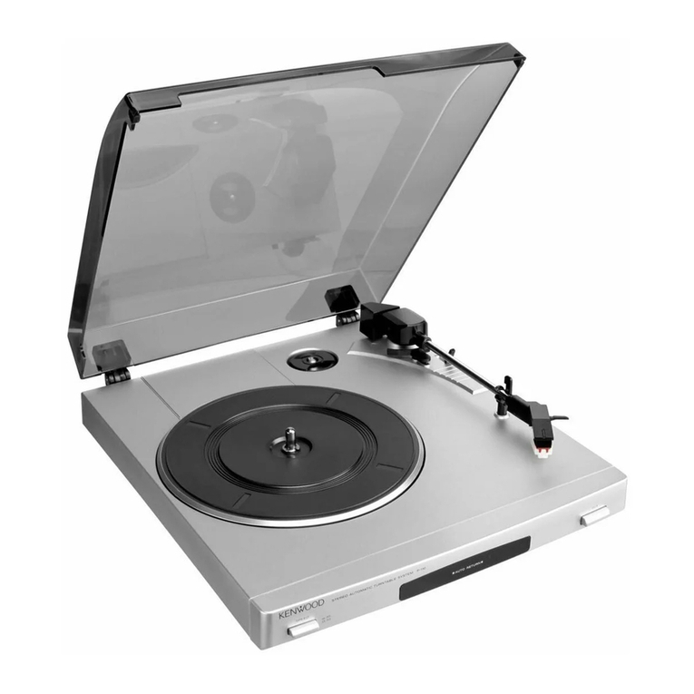
Kenwood
Kenwood P-100 User manual

Kenwood
Kenwood KD-650 User manual