CONTENTS
EXTERNAL
VIEW.
0.cc
occ
decsscesesacs
Seca
ie
acetates
tetie
coodd
ds
Bia
des
hese
ea
yaa
daGaea
cue
meets
Behe
3
INTERNAL
VW
ete
cd
nce
dd
iennes
Sestetade
sehen
dand aces
bee
dented
es
cue
tabsaneoauvenwepadee
saath
4
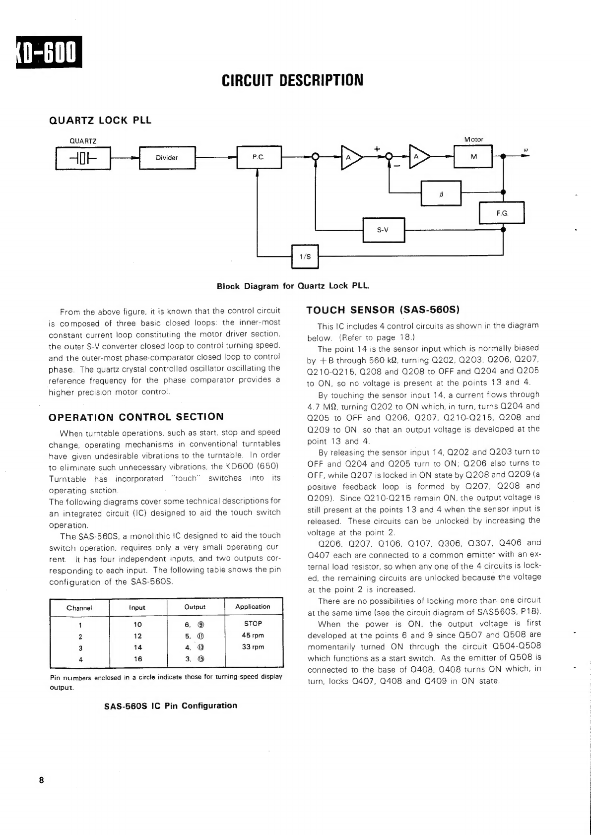
CIRCUIT
DESCRIPTION
ico
vsescssssesie
inna
disa
sees
nds
decciew
gene
Sane
Roce
acea
ie
eee
BLOCK
DIAGRAM
ME
GHANIUS
Wiiiiiiisscd
scacetcae
testes
thts
Seite
decd
scceseeuiskonn
veboeaeaovcs
ea
onaeh
oes tas
tude
aeaderdeedee
tet
DISASSEMBLY
FOR
REPAIR
.................:ccccceceeeee
nec
ne
etree
eee
bene
ee
rea
n
een
eee
eee
ant
E
nese
ees
ADIUSTIMEN
TT
oiscisiikscatssccned
cosnwciaacs
caias
daveiueee
rea
deeds
ciiaqwinos
coceh
thant
ped
ve
dace
dea
eredomernegened
EXPLODED:
VIEW
a
wskicisincicncg
ed
iadh
cides
ee
nstin corer eater
ccdote
aeves
ck.
adidas
sha
ahieseigue
paatekeereesieae’
EXPLODED
VIEW
PARTS
LIST
...........0...0.0c
cece
eter
e
tebe ener
entre
te
etree
renee
neen
ees
.
PARTS
(LIST
ic
iessctissensetiphetvieanade
sa
sseieatsa
saad
atatiaw
rata
cont
evederaienb
een
canebighs
dae
smianh
as
eve
eee
DESTINATIONS’
PARTS
LIST...........
Bag
Cpe
E
ey
dale
bg
WRAP
eR
SUR
LE
a
ot
ewan
TRG
PACKING
REVISED
CIR
CUUT
2iceisikcBiccastv
etnias
dead
coapcviesens
vorsaupcdewd
ebaie
ous
Neel
eee
seaesd
es
Decne
aes
PCABO
AR
Dies
tctck
cnt
teas
ba
bie
boesuta
daca
saaainsie
eee
merino
es
euictosatta
caitalese
wee
eens
wut
ohne
d
tits
sees,
cee
SCHEMATIC
DIAGRAM
boii
osscissssseacscop
vacuea
ae
ctegucaceten
tel
Secdss
nie
de
biaadabs
ay
vnvadae
Oarae
neg
ees
WAVEFORM
OF
CHECK
POINTS
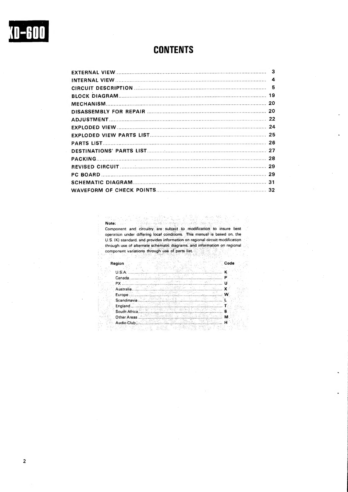
Note:
fry
Component
and
circuitry:
‘are
subject
to
modification’
to
insure
best
operation
under
differing.
local
conditions.
This
manual
is
based
on,
the
U.S.
(K)
standard,
and.
provides
information
on
regional
circuit
modification
through
use
of
alternate
schematic
diagrams,
and
information
on
regional
component
variations
through
use
of
parts
list...”
s
Region
:
Code
WSIAS
reccastans
vet
inetevaseosuceseviasedeninaustnees
pitignse
Sastre
K
Canada....cccscciasesi
he
eghetih.
ceo
Gosat
ssslbed
ie
eeiasedseeseves
P
PX
rcdcsctes'sbveok
cues
Crate
clucus
ox
Soave
ranaees
wces
caiboass
Mitaner
eaten
oe
tet
eee
U
ANUS
tral,
sj
sacs
Sh
0s
oa ae
ae
eco
saaawi
tetceeddsad
Fieteedere
geen!
x
EWPODO
123g.
sein
ise
Sdapesecneatepohsecenenes
cot
patevcheoutacealSocevseqegecued
Ww
Scandinavia
secrecy
teh
cold
Mabvelecdetandbeccdscponsccoghesde'
L
England
.....i.0..
South
Africa...
Other
Areas
....
Audio.
Clubj.i.
Gis
specie