BioSync Fingerprint Readers
- 7 - P/N: 02304-003 Rev. B
- In Doors.NET go to Setup >> Hardware Setup >> All.
- Locate and highlight the BioSync reader in the hardware tree.
- Ensure Advanced View is enabled for the reader properties.
- Locate LED/Buzzer.
- Set the reader for Separate Red and Green, No Buzzer.
Note: This will set the controller to use the buzzer for controlling the second LED line and
because of this the reader does not generate any sound when the door is forced or held
open.
lWhen using BioSync readers with EP controllers you have to use custom LED Modes
to define the LED behavior for the various reader modes (i.e - access granted, access
denied, locked, unlocked, lockdown, etc). Setting up and using Custom LED Modes is
covered in a separate section and available as a standalone document (p/n: 02315-
001).
General Notes
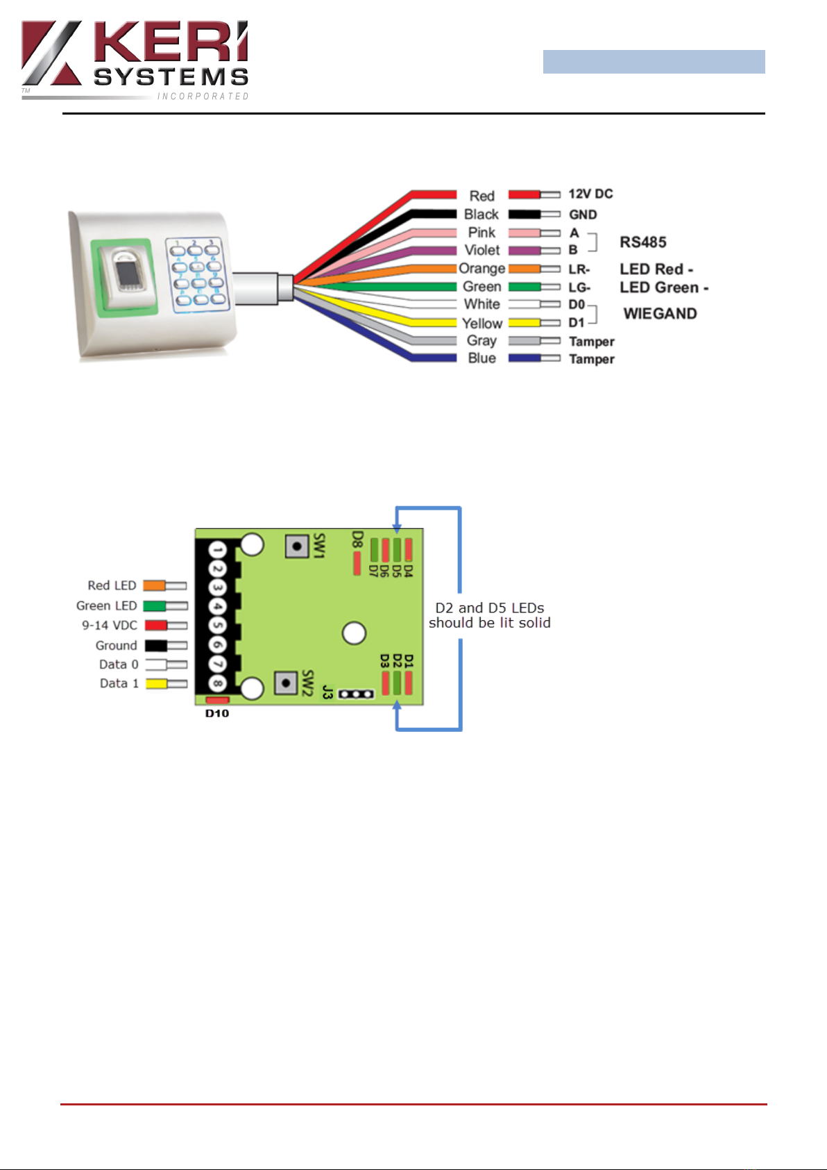
lThe shield wire connects with the black (Ground) wire at the controller. At the
reader side they are kept separate to prevent a ground loop.
lThe BioSync readers can be connected to virtually any controllers that conforms to
Wiegand format standards (standard 26-bit or a custom Wiegand format).
lThe maximum reader cable run distance for the BioSync readers is 500 feet (as per
industry standard specifications).
lTypically the BioSync readers will be powered from the controller so ensure the con-
troller's power supply outputs enough current for the controller and all connected
devices.
lThe current draw for the BioSync KBF-3KP is approx. 130mA max.