Kersten KM 19060 H User manual

Original operating
instructions
Agricultural Sweeper
KM 19060 H; KM 22560 H
KM 25060 H; KM 27060 H
Manufactures by
Kersten Arealmaschinen GmbH
Empeler Straße 95
D - 46459 Rees
www.kersten-maschinen.de
Distributed in UK by
Kersten (UK) Ltd Tel. 0118 986 9253
Progress House 39 Boulton Road
Reading, RG2 0NH
www.kerstenuk.com - info@kerstenuk.com
Product Number: B00031 From machine- No:Rev.: R00 Stand: 11.07.2013

2

KM 19060 H; KM 22560 H; KM 25060 H; KM 27060 H
3
Table of Contents
1
Introduction.......................................................................................................... 4
2
About this manual................................................................................................ 5
2.1
BEFORE COMMISSIONING .........................................................................................................5
2.2
HINWEISE ZU DIESER BETRIEBSANLEITUNG ..........................................................................5
3
Safety instructions for attachments................................................................... 6
3.1
INTENDED USE ............................................................................................................................6
3.2
GENERAL SAFETY AND ACCIDENT PREVENTION RULES ......................................................6
3.3
USED PICTOGRAMS....................................................................................................................9
4 Disposal..........................................................Error! Bookmark notdefined.
5 Warranty ........................................................Error! Bookmark notdefined.
6 Recommendations ........................................Error! Book notdefined.
6.1 LUBRICANTS......................................................................Error!Textmarknotdefined.
6.2 MAINTENANCE AND REPAIR............................................Error!Textmark not defined.
7
Assembly............................................................................................................. 11
7.1
CONSTRUCTION OF THE SWEEPING MACHINE ..........................................................................11
7.2
ASSEMBLY OF DIRT MIXER AND SPLASH PROTECTION ......................................................12
7.3
ASSEMBLY SIDEBESEN ............................................................................................................13
8
Service ................................................................................................................ 14
8.1
OPERATING INSTRUCTIONS - SWEEPING MACHINE ..................................................................14
8.2
DIRT MORTAR CONTAINER - ADJUSTMENT...........................................................................15
8.3
SIDEBOOK - ADJUSTMENT.......................................................................................................16
9
Maintenance ....................................................................................................... 17
9.1
GENERAL MAINTENANCE INSTRUCTIONS.............................................................................17
9.2
DAILY TESTING.......................................................................................................................... 17
9.3
MAINTENANCE AFTER 20 HOURS OF OPERATION OR LONGER SERVICE LIFE................ 17
9.4
STORAGE ...................................................................................................................................17
9.5
TROUBLESHOOTING AND TROUBLESHOOTING.................................................................... 18
9.6
INSTALLATION OF THE CYLINDER .......................................................................................... 19
10
Technical data .................................................................................................... 20
10.1
SWEEPER...................................................................................................................................20
10.2
DIMENSION SHEET....................................................................................................................20
10.3
DELIVERY SERIAL .....................................................................................................................20
10.4
ADDITIONAL EQUIPMENT.........................................................................................................20
11
EC – Declaration of Conformity ........................................................................ 21

KM 19060 H; KM 22560 H; KM 25060 H; KM 27060 H
4
1 Introduction
Dear Customer,
Thank you for choosing a quality product from Kersten.
This product has been manufactured according to the most up-to-date production methods and extensive quality
assurance measures, because only when you are satisfied with your device, our goal is reached.
Before using this machine or implement for the first time, please read this manual thoroughly and thoroughly.
Keep this manual handy. If necessary, you can read important information and handling instructions.
Have fun with your Kersten device wishes you
Dip.-Ing.(FH) Robert Bosch
Management

KM 19060 H; KM 22560 H; KM 25060 H; KM 27060 H
5
2 About this manual
The machine or implement is subject to technical progress. All information, illustrations and
technical data are up-to-date at the time of publication. Changes in the sense of technical progress
are reserved to the manufacturer at any time.
2.1
Before commissioning
As self-propelled implements and implements are subject to considerable accident or danger
sources if not used properly, the first time the Kersten implement is commissioned, it must be
instructed by competent and authorized persons absolutely necessary.
The best way to familiarize yourself with its basic functions and its handling is to choose a free
and level terrain for your first trip.
•You reduce the risk of accidents on your part or third parties!
For further information and difficulties of any kind, please contact the dealer, importer or directly to
the manufacturer.
•Be sure to read the safety instructions on the following pages!
•Read the operating instructions before commissioning!
•Pass on all safety instructions to other users!
2.2
Notes on this operating manual
Notes on this operating manual Enumerations are marked with eye-catching points.
Example:
•Text
•Text
Instructions are marked according to the order in which they are to be carried out.
Example:
1.
Text
2.
Text

KM 19060 H; KM 22560 H; KM 25060 H; KM 27060 H
6
3 Safety instructions for attachments
The most important safety instructions in this manual can not cover all possibilities. It goes
without saying that common sense and caution are factors that are not built into a machine, but
must be brought by the person who uses and maintains the machine.
In order to keep the accident risk as low as possible, please observe the following
subchapters.
3.1
Intended use
• The sweeper has been developed for sweeping on paved surfaces, sidewalks and facilities for
the usual or common use in the area of area care.
•Any other use is considered improper use. The manufacturer is not liable for damage resulting
from this, the risk being solely borne by the operator.
•Proper use also includes compliance with the operating, maintenance and service conditions
specified by the manufacturer.
•The attachment mayonly be used, maintained and repaired by persons who are familiar with it
and have been informed of the dangers.
•The relevant accident prevention regulations as well as the other generally recognized safety
and occupational health rules must be observed.
•Unauthorized modifications to the machine lead to the exclusion of liability of the manufacturer
for the resulting damage.
3.2
General safety and accident prevention regulations
3.2.1
Basic rules
•In addition to the instructions in this operating manual, observe the generalvalid
safety and accident prevention regulations!
•The implement must not be operated by persons under the age of 16, not even
under the supervision of an adult! Children and adolescents should be instructed,
not
•to play with it.
•Only trained personnel or persons may use this machine!
•When using public traffic routes, observe the relevant regulations!
•The clothing of the user should be tight. Avoid loose-fitting clothing and wear
sturdy shoes or safety shoes!
•Only work in good visibility and light conditions!
•The attached warning and information signs provide important information for safe
operation; the attention serves your safety!
•Beware of oscillating brushes - keep safety distance!
•Be careful with trailing machine parts. Wait for work on these until they are
completely stopped!
•There are crushing and shearing points on driven parts!
•Driving behavior, steering and, if applicable, braking capability and tilting behavior
are influenced by mounted or attached implements and load. For this reason, only
implements approved by the manufacturer may be used. The working speed must
be adapted to the respective conditions.
•Unauthorized conversions that endanger the operational safety of the machine are
prohibited!
•Check the machine for operational safety before each use!
•Never remove or change protective devices!
•Never go under the unsecured device for repair or inspection!

7
KM 19060 H; KM 22560 H; KM 25060 H; KM 27060 H
3.2.2
Occupational and danger area
•
The user is responsible to third parties in the workarea!
•
Staying in the danger area of the machine isprohibited!
•
Before switching on the implement and starting, check the near area. Pay special attention
to children and animals. Ensure sufficient visibility!
•
Before starting work, foreign bodies should be removed from the surface to be worked. Pay
attention to other foreign objects during work and eliminate them in good time.
•
When working in enclosed areas, the safety distance to the border must be maintainedso
as not to damage the machine or brushes.
•
When working in the immediate vicinity of public roads and paths, they should not be
approached longitudinally, but preferably as far as possible, because this minimizes the
risk of injury to third parties by flying objects.
•
When working on public roads and squares or in the immediate vicinity, warning and
danger signs should be set up in order to attract the attention of thirdparties.
3.2.3 Before starting work
•
Before starting work, please familiarize yourself with all equipment and actuators and their
function and make sure that all safety devices are properly grown and in protective position.
During the work assignment it is too late!
3.2.4 During operation
•
Never leave the control room while driving!
•
Do not leave the operating station until the brushes of the attachment come to astandstill!
•
During operation do not make any adjustments to the attachment - risk of accident! The
transportation of persons and objects is prohibited!
•
If, for example, the attachment has caught a foreign object and blocked it, stop the engine
and clean the attachment with a suitable tool! at
•
Interventions or cleaning of the attachment always switch off the engine! You'rewelcome
•
Observe the safety instructions of the self-propelled implement.
•
If the self-propelled implement or attachment is damaged, stop the engine immediately and
have the damage repaired.
3.2.5 Leaving the machine
•
By using wheel chocks or, if necessary, by the parking brake, secure the machinefrom
rolling away when leaving the vehicle.
•
Secure the device against unauthorized use!
•
Never leave the appliance unattended while it is still in operation!
3.2.6 Screw connections and tires
•
When working on the wheels, make sure that the device is safely parked andsecured
against rolling away!
•
Check nuts and bolts regularly for tightness and tighten if necessary.
•
Repair work on the tires may only be carried out by qualified personnel and with a suitable
assembly tool!
•
If the tire pressure is too high there is a risk of explosion!
•
Check the air pressure regularly.

8
KM 19060 H; KM 22560 H; KM 25060 H; KM 27060 H
3.2.7 Coupling and uncoupling attachments
•
Only connect and disconnect implements with the engine switched off and thePTO
switched off.
•
When changing attachments and their parts, use suitable tools and wear gloves.
•
When mounting and dismounting, bring the required support equipment into the respective
position and ensure sufficient stability.
•
Secure the self-propelled work machine and the attachment to prevent it fromrolling
(parking brake, wheel chocks).
•
When attaching attachments, there is a risk of injury (crushing). Special care isnecessary.
•
Attach implements according to regulations and fix at the prescribed places.
3.2.8 Maintenance, cleaning and repair work
•
Only carry out maintenance and cleaning work with the drive switched off and themotor
stationary!
•
If guards and working tools are subject to wear, these must be checked regularly and
replaced if necessary.
•
Only use original spare parts from the manufacturer, as these meet the technical
requirements and thus the risk of accidents is minimized!
•
Cleaning with the high-pressure cleaner should be carried out in such a way that the water
jet is not directly in storage, turned parts, grease nipples, shaft seals, wheel hubs etc. is
held.
After each cleaning with the high-pressure cleaner, the lubricating be gr
eased. In the case of
infringement, the right to guarantee expires!
•
Check the moving parts for ease of movement and if necessary grease them!
•
After maintenance and cleaning work, be sure to replace the guards and put them inthe
protective position!
•
To avoid the risk of fire, keep the machine clean!
•
Check nuts and bolts regularly for tightness and tighten if necessary.
•
During maintenance, cleaning and repair work on the raised device always makesure that it
is protected by suitable support elements!
•
Before doing anyrepairs, make sure the hydraulic system is depressurized, because fluids
under pressure can penetrate the skin and cause serious injury cause! Therefore, seek
medical attention immediately - risk of infection!
•
Repairs may only be carried out by qualifiedpersonnel.
•
Check hydraulic hose lines for damage and aging at regular intervals and replace if
necessary.
•
When carrying out welding work on the tractor or on the mounted implement, disconnect the
battery.
•
Repair work such as welding, grinding, drilling, etc. must not be carried out onload-
bearing and other safety-related parts such as frames, axles, etc.!

9
KM 19060 H; KM 22560 H; KM 25060 H; KM 27060 H
3.3 Used pictograms
Explanation of the pictograms used:
Before commissioning read and observe the
operating instructions and safety instructions.
Never open or remove protective devices while the
engine is running!
Follow the instructions in the technical manual.
Smudge!
Touch machine parts only when they have come to a
complete stop.
Danger from passing parts while the engine is
running - keep safety distance!

10
KM 19060 H; KM 22560 H; KM 25060 H; KM 27060 H
4 Disposal
The equipment must be disposed of in accordance with local, state, or local regulations.
Depending on the material, you can dispose of the parts in the form of residual waste, special
waste or recycling. The company Kersten Arealmaschinen GmbH assumes no disposal.
5 Warranty
The device is accompanied by a sales message, which among other things determines the time for
the start of the warranty period. When selling the device, please complete the sales message
completely and send it back to us within 14 days. If warranty claims are asserted without us having
received a sales notice, no warranty service will be provided.
Warranty claims should be submitted promptly, but no later than six weeks after the occurrence of
the damage, giving details of the purchase data, otherwise no warranty service will be provided.
Complaints must be confirmed by the company Kersten Arealmaschinen GmbH. Wear parts are
excluded from the warranty. Furthermore, the warranty expires due to improper operation, when
performing no or incorrect maintenance work, when using inadmissible equipment and when using
non-original spare parts.
6 Recommendations
6.1
Lubricants
For engine and gearbox, use the specified lubricants (see under "Technical data").
For "open" lubrication points or nipple points, we recommend using bio lubricant oil or bio lubricant
grease. With the use of bio lubricant, you act ecologically correct, protect the environment and
promote the health of people, animals and plants.
6.2
Fuels
The built-up B & S or Honda engine can be easily operated with commercial unleaded normal and
premium gasoline and leaded premium gasoline.
Do not add oil to the gasoline.
If unleaded petrol is used for the environment, engines that are to be decommissioned for more
than 30 days should have their fuel drained completely to avoid resin residues in the carburetor,
fuel filter and tank, or to add a fuel stabilizer to the fuel.
6.3
Maintenance and repair
Your dealer has trained mechanics who perform proper maintenance and repair. You should only
carry out major maintenance work and repairs yourself if you have the appropriate tools and
knowledge of machines and internal combustion engines.

11
KM 19060 H; KM 22560 H; KM 25060 H; KM 27060 H
1 Anbau der Kehrmaschine
Schwerste Verletzungen des Bedieners oder Dritter können eintreten.
Schalten Sie den Traktor aus und ziehen Sie den Zündschlüssel ab, bevor Sie die
Anbaukehrmaschine montieren oder demontieren.
Die Kehrmaschine in die Front- oder Heckhydraulik bzw. in den Frontlader des Schleppers
einhängen.
Dabei die horizontale Breite des Anbaurahmens je nach der Schleppertype einstellen und mit
zwei Schrauben rechts und links arretieren.
Den Oberlenker regulieren, bis dass das Dach der Kehrmaschine in der Waagerechten ist.
Nun die zwei Hydraulikschläuche (Vor- und Rücklauf) des Kehrwalzenantriebs durch die Ringe
am
Anbaurahmen zum Schlepper führen und in die Steckkupplung so einstecken, dass die
Kehrwalzen-Drehrichtung stimmt.
7 Installation
7.
7.1
Attachment of the sweeper
Severe injuries to the operator or third parties may occur.
Switch off the tractor and remove the ignition key before removing the ignition
Mount or dismantle the attachment sweeper.
The sweeper in the front or rear hydraulics or in the front loader of the tractor
Hook.
In doing so, set the horizontal width of the attachment frame according to the tractor type and with
lock two screws right and left.
Adjust the top link until the roof of the sweeper is horizontal.
Now the two hydraulic hoses (supply and return) of the sweeping roller drive through the rings
on the attachment frame lead to the tractor and insert it into the plug - in coupling so that the
Sweeping roller rotation is correct.
Three-point
Cat I and II
Mounting frame
(ABR) 60 Rear
Sweeper
Basic unit
Fig.1

12
KM 19060 H; KM 22560 H; KM 25060 H; KM 27060 H
7.2
Installation of dirt collector and splash guard
First, place the holders for hydraulic tank emptying on the left and right of the sweeper's carrier pipes.
Then insert the container and the splash guard on both sides through the bolts "A" and the container
additionally through the bolt "B" as shown in Fig.2.
The bolts are each secured by linch pin.
The splash guard falls by its own weight diagonally against the sweeper base housing and the two rubber
straps top and bottom close the space between sweeper and dirt collector.
To empty the container, the hydraulic cylinders pull in, so the container folds up.
Notes: Tighten all hydraulic fittings before the test run.
Support wheel
adjustment
Return tugs
Forward tugs
Extend
cylinder
Collecting container
height adjustment
Support tube
Cylinder
Move
cylinder
A
B
Linch pin
Dirt collection
Splash guard
Holder for hydraulic
container emptying
Fig.2
13
KM 19060 H; KM 22560 H; KM 25060 H; KM 27060 H
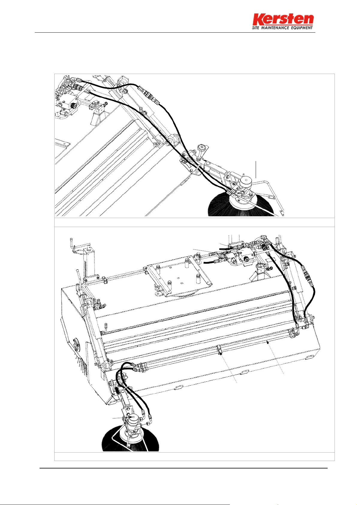
7.3
Montage side brush
The hydraulic hoses are mounted as shown in fig.3 and fig.4.
For the left side brush, wire holders and piping are mounted in the holes provided on the sump.
Hydraulic motor
Fig.3 in the direction of travel left
Flow control valve
Pressure sequence valve
Conductor
holder
Piping
Hydraulic motor
Fig.4 in the direction of travel right

14
KM 19060 H; KM 22560 H; KM 25060 H; KM 27060 H
8 Operation
8.1
Operating instructions - Sweeper
Broom setting:
Usethetwist handles toadjustthetwosupport wheels insuchawaythatthesweeping roller pushes
off a 4 cm wide strip on the floor.
Pay attention to the same setting of the two support wheels!
Note:
A sweeping roller that is set too tight will not result in better sweeping results but will result in higher
wear of the sweeping roller. Depending on the wear of the brush, it is important to adjust the height
setting on the support wheels.
Abb.5
Storage:
Never store the sweeper on the broom.
Relieve the sweeping roller with the help of the two support wheels.
Put the dust caps over the hydraulic plugs!
Pivoting the sweeper:
According to the work involved, the sweeper can be swiveled straight or left or right over the
turntable. Lock the handrail in the desired position.
Dust cap
Slewing ring
Abb.6
Support wheel adjustment
Height scale
Stabilizer
4cm

KM 19060 H; KM 22560 H; KM 25060 H; KM 27060 H
15
8.2
Dirt collecting container - setting
The ground clearance of the collecting tank should be 4 - 6 cm evenly and is adjusted via the two
twist grips on the left and right support tube.
Attention: Please adjust carefully for very uneven ground conditions!
Fig.7
To empty the container, pull out the lifting cylinder, then the container folds up, see
Fig.8.
Fig.8
Dirt collecting
container
Heavy duty
impeller
4 - 6cm
Lifting cylinder
KM 19060 H; KM 22560 H; KM 25060 H; KM 27060 H
16
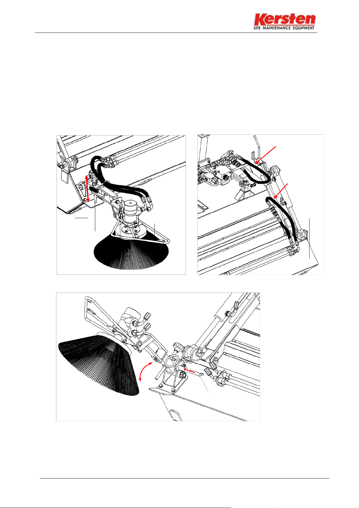
8.3
Side brush - Setting
Please do not adjust the side broom until the main broom and the dirt collector are set.
The height is adjusted by operating the spindle on the connection plate, see Fig.9
The best sweeping performance with side brushes results in a sweeping slightly tilted to the
middle of the road sweeper.
If the side broom is not in use, fold it up and secure it, this is also the storage position, see Fig.11.
When dismantling the side broom and operating the sweeper without a side brush, always insert
the hydraulic hoses into circulation, Fig.10.
Make sure the hydraulic connectors are clean!
Fig.9
Fig.11
Fig.10
Circulation
without dirt
collector
Circulation
without side
brush
Collecting
containers
Side brush
Connection
plate
Spindle
Spindle for
tilt
adjustment
Locking pin

KM 19060 H; KM 22560 H; KM 25060 H; KM 27060 H
17
9 Maintenance
9.1
General maintenance instructions
• Non-compliance may result in personal injury or damage to the machine. Before each use of the
machine check all safety-relevant parts.
•The machine must be regularly serviced.
•Repairs, maintenance and cleaning work as well as the elimination of malfunctions must only be
carried out with the implement disconnected. To do this, also disconnect the hydraulic connection to
the single axle.
•During all work, the machine must be secured against rolling or tipping by taking suitablemeasures.
•Regularly check nuts and bolts for tightness and retighten if necessary.
•Only use original spare parts from the manufacturer!
•Check all bolt and bolt connections after the first 5 hours of operation.
•Once all work has been completed, all disassembled protective devices must be properlyreplaced.
•Lubricate or lubricate all moving parts. *
9.2
Daily exam
•Check the tools for tightness.
•Check the safety elements and moving parts for wear before each use.
•Perform a test run before each use.
•Clean the device after each use.
9.3
Maintenance after 20 operating hours or longer downtime
•At regular intervals and always at the beginning and end of the season, the moving parts of the unit
must be greased or oiled.
•Lubricating nipples are located in the wheel receivers and in the bearing pin of the connection
mount, these lubricate regularly.
•Lubricate the attachment of the attachment regularly.
9.4
Storage
If the machine is not used for a long time, the following measures are recommended:
1.
Carry out cleaning
2.
Check the function of all parts
3.
Check all screws and bolts for tightness and retighten them if necessary.
4.
Replace worn or damaged components, only use original Kersten spareparts!
5.
Regressed lubrication points (=> grease nipple)
6.
Subordinate machine
•
To prevent corrosion, protect the machine from weathering. Do not place the
machine in damp rooms, stables or artificial fertilizer warehouses.
7.
Cover the machine with a cloth or similar.

KM 19060 H; KM 22560 H; KM 25060 H; KM 27060 H
18
9.5
Faults and their rectification
This chapter describes in more detail the most important faults that can occur during operation on
the sweeper. Faults which require major intervention must always be rectified by your specialist
workshop.
Malfunction: Possible cause: Remedy:
Hydraulic motor
does not turn
Brushes do not
come on tours
Internal combustion engine is
not running
Hydraulic power take-off not
switched on.
Hydraulic hoses not connected.
Hydraulic connector notengaged.
No hydraulic fluid in the hydraulic
tank.
Speed set too low
Start combustion engine.
Switch on hydraulic auxiliary drive.
Connect hydraulic hoses.
Check hydraulic connector, insert if
necessary until it clicks into place.
Add hydraulic fluid to the hydraulic tank.
Increase speed.
Hydraulic fluid too low Add hydraulic fluid to thehydraulic
tank
Leakage on the hydraulic house.
Leakage at the hydraulic connectors.
Leakage at the hydraulic
screw connection.
Contact pressure on the worksurface
too large.
Replace hydraulic hoses.
Release hydraulic connector and insert again until
it clicks into place. Should leakage continue; Check
hydraulic connector and replace ifnecessary.
Slightly loosen the hydraulic screw connection,
move the hose slightly and tighten the hydraulic
screw connection again.
Align the machine higher so that the brushes are
relieved.
Height
adjustmentstiff Threaded spindle dirty.
Pickup dirty, adjusting screws
screwed in too far.
Release lever, unscrew jockey wheel.
Clean spindle and jockey wheel and grease.
Remove dirt from the receiving socket and
the pick-up tube and then grease them
fresh.
Debris remains
lying /
does notsweep
clean
Driving speed too high
Broom speed too high / too low
Sweeping roller height set too high
Collecting container set too high
Side brush set incorrectly
Reduce driving speed.
Reduce or increase broom speed
Adjust sweeping roller height according to
specifications
Set the collection container to the correct height
Adjust the side brush properl
KM 19060 H; KM 22560 H; KM 25060 H; KM 27060 H
19
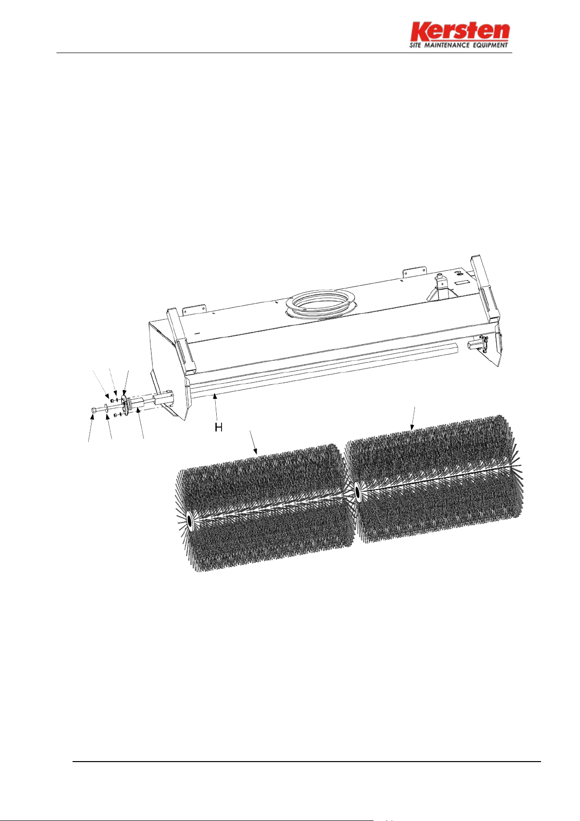
10 Installing the sweeping roller
•
In the direction of travel on the right, remove the tension rod (A) with washer (B) from the
sweeper's main body.
•
Loosen the three nuts (C) with the respective spring washer (D) and then pull outthe
bearing shells (E) with drive stub (G).
•
To remove the drive tube (H) and the roller brush (J) and (K), the sweeper must belifted.
•
Now the first half of the sweeping roller (J), then the drive tube (G) and the secondhalf
of the sweeping roller (K) can be pulled out.
•
Mount the two-piece sweeping roller and the drive tube in reverse order to the drivestub
and the tension rod.
C D E
K
J
A
B
G

KM 19060 H; KM 22560 H; KM 25060 H; KM 27060 H
20
11 Technical data
11.1
Sweeper
Type
KM 19060 H
KM 22560 H
KM 25060 H
KM 27060 H
Working width a
190 cm
225 cm
250 cm
270 cm
Sweeping roller
diameter
60 cm 60 cm 60 cm 60 cm
Drive
hydraulic
hydraulic
hydraulic
hydraulic
Mass
kg
kg
kg
kg
Hydraulic oil
Avia N 46
Avia N 46
Avia N 46
Avia N 46
Amount of oil
ca. 11.5 Liter
ca. 11.5 Liter
ca. 11.5 Liter
Ca. 11.5 Liter
11.2
Dimension sheet
Dimensions for working width a can be found in Table 10.1.
11.3
Scope of delivery as standard
•
Attachment frame (tractor-dependent)
•
Combined rotary roller with poly-twist trim, five-row
11.4
Additional equipment
•
Disc Broom
•
Hydraulic swivel device right, left
•
Dirt collecting container with hydraulic container emptying
•
Heavy duty impeller
•
Air-tired wheels 11 x 7.00-4
•
Air-tired wheels 16 x 6.50-8-4
•
On scratch bar
•
Further sweeping rollers on request
Fig.14
This manual suits for next models
4
Table of contents
Other Kersten Farm Equipment manuals


