Kersten KM 10037 H-FKDR User manual
Order number: B00048 From machine - No: Rev.R00 Data: 07.12.2015
O
Or
ri
ig
gi
in
na
al
l
o
op
pe
er
ra
at
ti
in
ng
g
i
in
ns
st
tr
ru
uc
ct
ti
io
on
ns
s
Front sweeping machine
KM 10037 H-FKDR;
KM 11537 H-FKDR;
KM 12537 H-FKDR
Manufactures by
Kersten Arealmaschinen GmbH
Empeler Straße 95
D - 46459 Rees
www.kersten-maschinen.de
Distributed in UK by
Kersten (UK) Ltd Tel. 0118 986 9253
Progrees House 39 Boulton Road
Reading, RG2 0NH
www.kerstenuk.com - [email protected]

1

Table of Contents
2
1
Foreword.......................................................................................................................................................... 3
2
About this manual...................................................................................................................................4
2.1
BEFORE COMMISSIONING.......................................................................................................................................................................4
2.2
NOTES ABOUT THIS MANUAL.................................................................................................................................................................4
3
Safety instructions for attachments......................................................................................................5
3.1
INTENDED USE..........................................................................................................................................................................................5
3.2
GENERAL SAFETY AND ACCIDENT PREVENTION RULES ..................................................................................................................5
3.3
MAINTENANCE AND REPAIR ...................................................................................................................................................................8
4
Disposal...................................................................................................................................................9
5
Warranty ..................................................................................................................................................9
6
Recommendations..................................................................................................................................9
6.1
LUBRICANTS..............................................................................................................................................................................................9
6.2
FUELS .........................................................................................................................................................................................................9
6.3
MAINTENANCE AND REPAIR ...................................................................................................................................................................9
7
Montage Front sweeping machine ........................................................................................................10
7.1
ADJUSTMENT FRONT TREADMILL..........................................................................................................................................................11
7.2
MOUNTING DIRT MOUNTING TANK ........................................................................................................................................................12
7.3
ADJUSTMENT DIRT CONTAINER.............................................................................................................................................................12
7.4
ASSEMBLY SIDEBESEN............................................................................................................................................................................13
7.5
MOUNTING WATER PRESSURE EQUIPMENT .......................................................................................................................................14
8
Service....................................................................................................................................................15
8.1
OPERATING INSTRUCTIONS - SWEEPING MACHINE...........................................................................................................................15
8.2
CONTAINERS ADJUSTMENT....................................................................................................................................................................15
8.3
SIDE BROOM ADJUSTMENT ....................................................................................................................................................................15
9
Maintenance...........................................................................................................................................16
9.1
GENERAL....................................................................................................................................................................................................16
9.2
MAINTENANCE...........................................................................................................................................................................................16
9.3
DAILY TESTING..........................................................................................................................................................................................16
9.4
MAINTENANCE AFTER 20 BZW. 100 HOURS OF OPERATION OR LONGER SERVICE LIFE............................................................16
9.5
TROUBLESHOOTING AND TROUBLESHOOTING..................................................................................................................................17
9.6
INSTALLATION OF THE CYLINDER .........................................................................................................................................................18
10
Technical specifications........................................................................................................................19
10.1
KEHR MACHINE .........................................................................................................................................................................................19
10.2
DIMENSION SHEET ...................................................................................................................................................................................19
10.3
DELIVERY SERIAL.....................................................................................................................................................................................19
10.4
ADDITIONAL EQUIPMENT.........................................................................................................................................................................19
11
EC Declaration of Conformity...............................................................................................................20

3
Introduction
1 Introduction
Dear Customer,
Thank you for choosing a quality product from Kersten.
This product has been manufactured according to the most up-to-date production methods and extensive
quality assurance measures, because only when you are satisfied with your device, our goal is reached.
Before using this machine or implement for the first time, please read this manual thoroughly and thoroughly.
Keep this manual handy. If necessary, you can read important information and handling instructions.
Have fun with your Kersten device wishes you
Dip.-Ing. (FH) Robert Bosch
Managing directors

4
About this manual
2 About this manual
The machine or implement is subject to technical progress. All information, illustrations and
technical data are up-to-date at the time of publication. Changes in the sense of technical progress
are reserved to the manufacturer at any time.
Therefore, no claims can be derived from the information and illustrations in this booklet.
2.1
Before commissioning
Since self-propelled implements and attachments can cause serious accidents or hazards if used
improperly, the first time the Kersten implement is commissioned, it must be instructed by competent and
authorized persons
absolutely necessary. The best way to familiarize yourself with its basic functions and its handling is to
choose a free and level terrain for your first trip.
•
You reduce the risk of accidents on your part or third parties!
For further information and difficulties of any kind, please contact the dealer, importer or directly to
the manufacturer.
•
Be sure to read the safety instructions on the following pages!
•
Be sure to read the operating instructions before starting up!
•
Pass on all safety instructions to other users!
2.2
Notes on this operating manual
•
Enumerations are marked with eye-catching points.
Example:
•
Text
•
Text
•
Instructions are marked according to the order in which they are to be executed.
Example:
1.
Text
2.
Text

5
Safety
3 Safety instructions for attachments
The most important safety instructions in this manual cannot cover all possibilities. It goes
without saying that common sense and caution are factors that are not built into a machine but
must be brought by the person who uses and maintains the machine.
In order to keep the accident risk as low as possible, please observe the following
subchapters.
3.1
Intended use
•
The sweeper has been developed for sweeping on paved surfaces, sidewalks and facilities for
the usual or common use in the area of area care.
•
Any other use is considered improper use. The manufacturer is not liable for damage resulting
from this, the risk being solely borne by the operator.
•
Proper use also includes compliance with the operating, maintenance and service conditions
specified by the manufacturer.
•
The attachment may only be used, maintained and repaired by persons who are familiar with it
and have been informed of the dangers.
•
The relevant accident prevention regulations as well as the other generally recognized safety
and occupational health rules must be observed.
•
Unauthorized modifications to the machine lead to the exclusion of liability of the manufacturer
for the resulting damage.
3.2
General safety and accident prevention regulations
3.2.1
Basic rules
•In addition to the instructions in this operating manual, observe the general valid safety and accident
prevention regulations!
•The implement may not be used by persons under the age of 16, not even under the supervision of a
Adults be served! Children and adolescents should be instructed not to play with it.
•
Only trained personnel or persons may use this machine!
•
When using public traffic routes, observe the relevant regulations!
•
The clothing of the user should be tight. Avoid loose-fitting clothing and wear sturdy shoes or safety
shoes!
•
Only work in good visibility and light conditions!
•
The attached warning and information signs provide important information for safe operation; the
attention serves your safety!
•
Beware of rotating sweeping roller - keep safety distance!
•
Be careful with trailing machine parts. Wait for work on these until they stop completely!
•
There are crushing and shearing points on driven parts!
•
Driving behavior, steering and, if applicable, braking capability and tilting behavior are influenced by
mounted or attached implements and load. For this reason, only implements approved by the
manufacturer may be used. The working speed must be adapted to the respective conditions.
•
Unauthorized conversions that endanger the operational safety of the machine are prohibited!
•
Check the machine for operational safety before each use!
•
Never remove or change protective devices!
•Never go under the unsecured device for repair or inspection!

6
Safety
3.2.2
Work and danger area
•
The user is responsible to third parties in the work area!
•
Staying in the danger area of the machine is prohibited!
•
Check the near area before switching on the implement and starting.
•
Pay special attention to children and animals. Ensure sufficient visibility!
•
Before starting work, remove foreign objects from the surface to be worked. Pay attention to other
foreign objects during work and eliminate them in good time.
•
When working in enclosed areas, the safety distance to the border must be maintained so as not to
damage the machine or sweeping roller.
•
When working in the immediate vicinity of public roads and paths, they should not be approached
across, as far as possible longitudinally, as this minimizes the risk of injury to third parties due to flying
objects.
•
When working on public roads and squares or in the immediate vicinity, warning and danger signs
should be set up in order to attract the attention of third parties.
3.2.3
Before starting work
•
Before starting work, familiarize yourself with all the equipment and actuators and their function,
and make sure that all safety devices are properly installed and in the protective position. It is too
late during the work assignment!
3.2.4
During operation
•
Never leave the operating area while driving!
•
Do not leave the operating station until the sweeping roller of the attachment comes to a standstill!
•
Do not make any adjustments to the attachment during operation - risk of accident!
•
The transport of persons and objects is prohibited!
•
If, for example, the attachment has caught a foreign object and blocked it, stop the engine and clean
the attachment with a suitable tool!
•
When intervening or cleaning the attachment, always switch off the engine! Please observe the safety
instructions of the self-propelled implement.
•
In the event of damage to the self-propelled implement or attachment, stop the engine immediately
and have the damage repaired.
3.2.5
Leaving the machine
•
By using wheel chocks or, if necessary, the parking brake, secure the machine from rolling away
when leaving the vehicle.
•
Secure the device against unauthorized use!
•
Never leave the appliance unattended while it is still in operation!
3.2.6
Screw connections and tires
•
When working on the wheels, make sure that the device is safely parked and secured against
rolling away!
•
Regularly check nuts and bolts for tightness and retighten if necessary.
•
Repair work on the tires must only be carried out by qualified personnel and with suitable
mounting tools!
•
If the tire pressure is too high there is a risk of explosion!
•
Check the air pressure regularly.

Safety
8
3.2.7
Coupling and uncoupling attachments
•
Only connect and disconnect attachments when the engine is off and the PTO is off.
•
When changing attachments and their parts, use suitable tools and
•
Wear gloves.
•
When mounting and dismounting, bring the required support equipment into the respective
position and ensure sufficient stability.
•
Secure the self-propelled work machine and the attachment against rolling away (parking brake,
wheel chocks).
•
When attaching attachments, there is a risk of injury (crushing). Special care is necessary.
•
Attach implements according to regulations and fix in the prescribed places.
3.2.8
Maintenance, cleaning and repair work
•
Only carry out maintenance and cleaning work with the drive switched off and the motor
stationary!
•
If guards and working tools are subject to wear, they must be checked regularly and
replaced if necessary.
•
Only use original spare parts from the manufacturer, as these comply with the technical
requirements and thus the risk of accidents is minimized!
•
Cleaning with the high-pressure cleaner should be carried out so that the water jet is not held
directly in bearings, turned parts, grease nipples, shaft seals, wheel hubs, etc. After each
cleaning with the high-pressure cleaner, the lubrication points must be re-greased. In the
case of infringement, the right to guarantee expires!
•
Check the moving parts for ease of movement and degrease if necessary!
•
After maintenance and cleaning work, be sure to replace the guards and put them in the
protective position!
•
To avoid the risk of fire, keep the machine clean!
•
Regularly check nuts and bolts for tightness and retighten if necessary.
•
When carrying out maintenance, cleaning and repair work on the lifted device always make
sure that it is protected by suitable support elements!
•
Before carrying out any repairs, make sure that the hydraulic system is depressurized,
because fluids under pressure can penetrate the skin and cause serious injuries! Therefore
immediately see a doctor - risk of infection!
•
Repairs may only be carried out by qualified personnel.
•
Check the hydraulic hose lines for damage and aging at regular intervals and replace if
necessary.
•
When welding the tractor or mounted equipment, disconnect the battery.
•
Repairs such as welding, grinding, drilling, etc. must not be carried out on structural and
other safety-related parts such as frames, axles, etc.!

Safety
9
3.3 Used pictograms
Explanation of the pictograms used:
Before commissioning read and observe the operating
instructions and safety instructions.
Never open or remove protective devices while the engine
is running!
Follow the instructions in the technical manual. Smudge!
Touch machine parts only when they have come to a
complete stop.
Danger from passing parts while the engine is running -
keep safety distance!

10
Disposal; Warranty and recommendations
4 Disposal
The equipment must be disposed of in accordance with local, state, or local regulations.
Depending on the material, you can dispose of the parts in the form of residual waste, special
waste or recycling. The company Kersten Arealmaschinen GmbH assumes no disposal.
5 Warranty
The device is accompanied by a sales message, which among other things determines the time for
the start of the warranty period. When selling the device, please complete the sales message
completely and send it back to us within 14 days. If warranty claims are asserted without us having
received a sales notice, no warranty service will be provided.
Warranty claims should be submitted promptly, but no later than six weeks after the occurrence of
the damage, giving details of the purchase data, otherwise no warranty service will be provided.
Complaints must be confirmed by the company Kersten Arealmaschinen GmbH. Wear parts are
excluded from the warranty. Furthermore, the warranty expires due to improper operation, when
performing no or incorrect maintenance work, when using inadmissible equipment and when using
non-original spare parts.
6 Recommendations
6.1
Lubricants
For engine and gearbox, use the specified lubricants (see under "Technical data").
For "open" lubrication points or nipple points, we recommend to use bio lubricant oil or bio
lubricant grease. With the use of bio lubricants you act ecologically correct, protect the
environment and promote the health of people, animals and plants.
6.2
Fuels
The built-up B & S or Honda engine can be easily operated with commercial unleaded normal and
premium gasoline and leaded premium gasoline.
Do not add oil to the gasoline.
If unleaded petrol is used for the environment, engines that are to be decommissioned for more
than 30 days should have their fuel drained completely to avoid resin residues in the carburetor, fuel
filter and tank, or to add a fuel stabilizer to the fuel.
6.3
Maintenance and repair
Your dealer has trained mechanics who perform proper maintenance and repair. You should only
carry out major maintenance work and repairs yourself if you have the appropriate tools and
knowledge of machines and internal combustion engines.
KM 10037; 11537 12537 H-FKDR
10
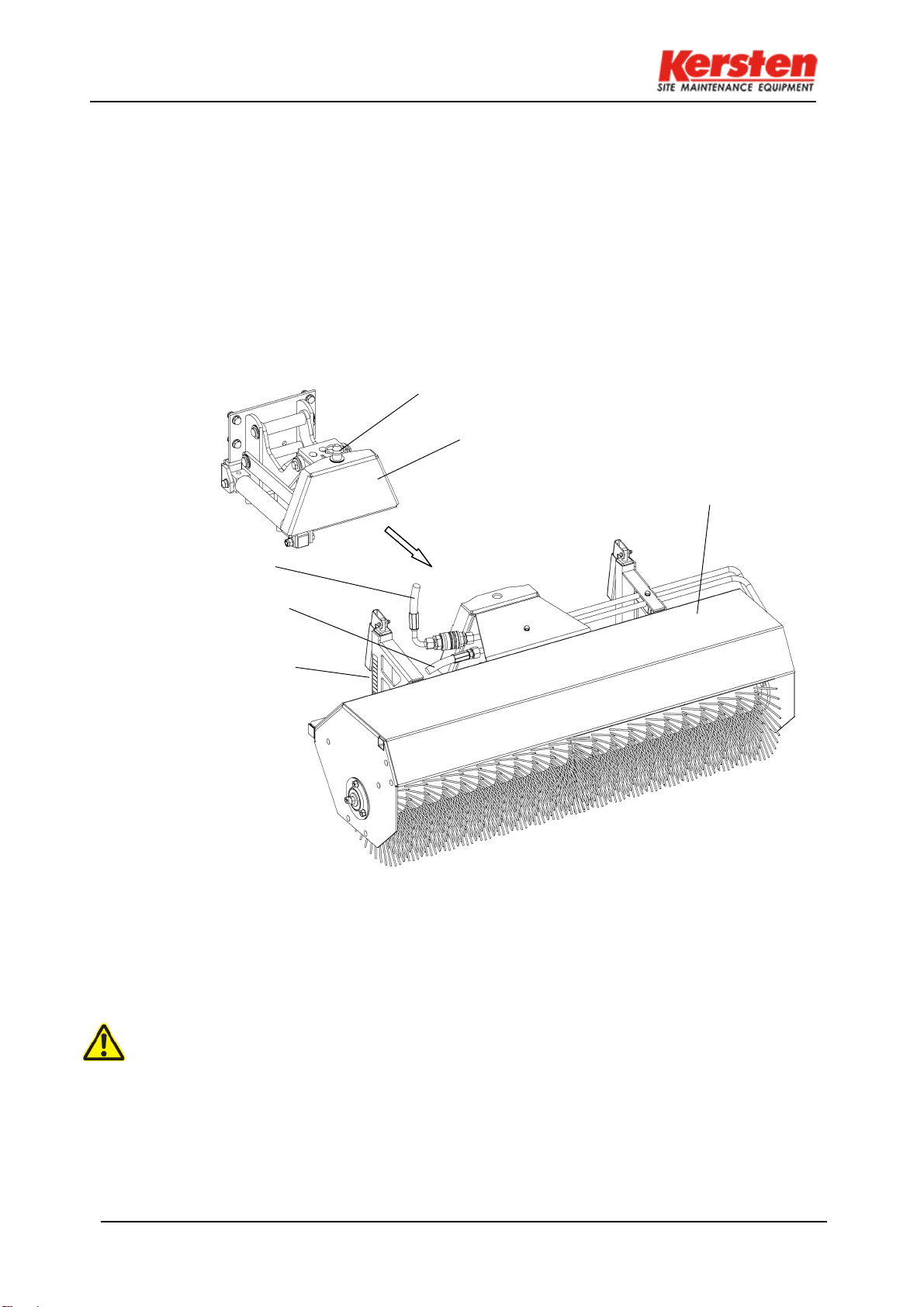
FKDR
sweeper
supply hose
return hose
Height adjustable
wheels
7 Assembly front sweeper
Severe injuries to the operator or third parties may occur.
Switch offthe vehicle and remove the ignition key before mounting or dismounting the mounted
sweeper. Hook the KM into the attachment triangle, whereby for the first time the connection parts
can be adjusted on the sweeping machine side to the desired lifting height.
Secure the attachment triangle with a cotter pin.
For easier attachment and removal of the KM we recommend the two additional side parking
supports with wheels (optional).
Insert the hydraulic hoses for the sweeper drive into the hydraulic sleeve and the hydraulic
connector.
safety pin
Fig.1
Hydraulic sleeve and hydraulic plug must always be in circulation when no sweeper is
connected. Otherwise, heat damage can occur. Absolutely pay attention to cleanliness of
the plug-in couplings.
KM 10037; 11537 12537 H-FKDR
11
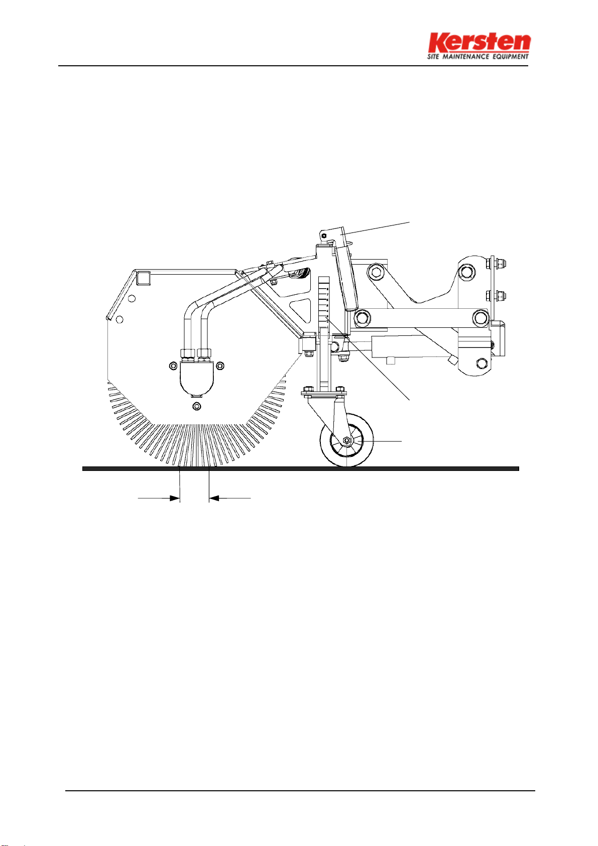
height scale
stabilizer
4cm
7.1
Adjustment front sweeper
Adjust the two support wheels with the help of the turning handles so that the sweeping roller
pushes off a 4 cm wide sweeping mirror on the floor. It is important to ensure the same setting of
the two sides after the marking on the scale graduation.
rotary handle
Fig.2

KM 10037; 11537 12537 H-FKDR
12
7.2
Assembly of dirt collector
•
Screw the two guide rails on the front, side right and left sweeper casings with two screws and
nuts each.
•
Fold up the container lock lever.
•
Hook the locking rod into the two guide rails on the right and left of the basic housing.
•
Move the locking lever downwards and place it in the pole holder.
7.3
Setting dirt collector
•
Use the swivel handles on the two guide rails to bring the collecting container to an even ground
clearance of 4 cm - pay attention to the graduation scale!
•
Re-adjust later, depending on the wear of the sweeping roller.
Attention! Never sweep sweeper with filled container!
Fig. 3
View in direction of travel left
4cm
4cm
Stabilizer
Height scale
Lock collection
container
Rotary handle
Guide rail
Open, hang up
KM 10037; 11537 12537 H-FKDR
13
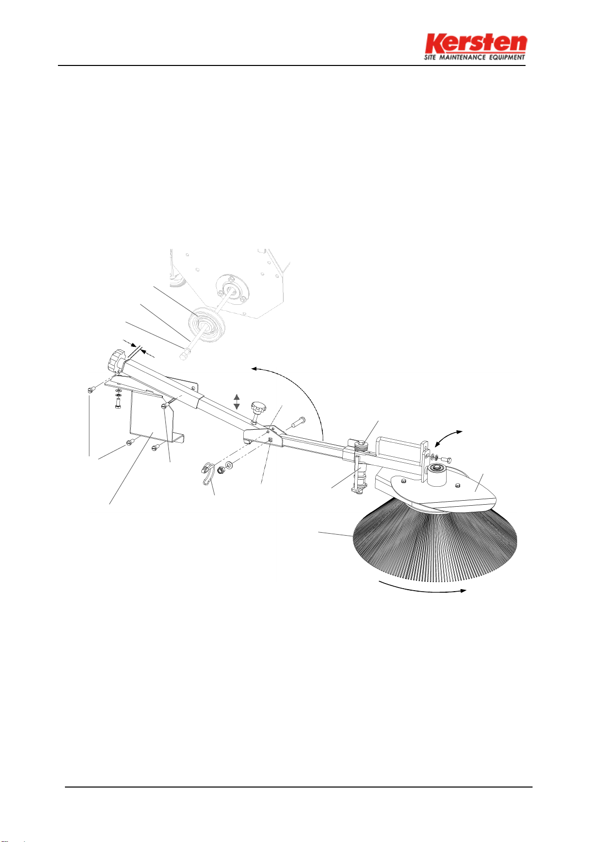
7.4
Montage side brush
•
When first installing, first pull out the tension rod on the right side of the sweeper and push on the
enclosed spring washer and pulley instead of the large diameter washer. Put everything together
in the sweeper.
•
Now screw the mounting plate with 4 screws, spring washers + nuts to the right-side plate (see 4 x
A). Mount the front side brush arm at "B" on the bracket of the mounting plate with screw M10 x
50 mm, washer and stop nut.
•
Place the V-belt around the pulley inside the mounting plate. When doing so, make sure that the
V-belt rear side of the roller is in contact with the "C" = white V-belt pulley!
•
Tighten the V-belt by turning handle E until it is about 5 mm between the handle and the pipe.
Note:
The sheet metal above the side broom serves as collision protection with the torsion spring.
Pulley tension
rod spring
washer
ca.5 mm
„E“
„D“
„H“
„K“
Tilt up to turn off and store
Torsion spring
„N“
„A“
Attachment
„A“
Linch pin
„B“
„C“
Collision
Side brush
AFig. 4
Adjustments for the side brush
"H" = height adjustment of the side broom by turning the star handle with threaded rod
"N" = inclination angle of the side brush can be changed by screw on the slot, e.g. for sweeping in street
gutters etc.
"K" = the side brush is temporarily not required for sweeping, remove the linch pin at "K" and tilt the front
side brush arm upwards until the linch pin under the pipe can secure this rest position in "K".
Easy disassembly of the side broom
To dismantle at "D" unscrew the screw, lock washer and washer and push the side brush arm completely
forwards. Take the V-belt out of the side of the pulley.
For assembly
First put the V-belt back on, screw on the side broom arm at "D".

KM 10037; 11537 12537 H-FKDR
14
7.5
Mounting water blasting device
•
When using the sweeper without collecting container, the water nozzles are mounted on top
of the sweeper roof.
•
When used with front hopper bottom, as shown in the figure 5 sketch.
•
In the case of the KM10037 H-FKDR and KM11537 H-FKDR, only one water nozzle can be
mounted in the center, or two water nozzles at a distance of approx. 500 mm from each other.
in each 250 mm distance to the center of the sweeper roof or the collecting container. With
the KM12537 H-FKDR, two water nozzles are mounted at a distance of 625 mm from each
other.
•
For each water nozzle holding plate, two bores with a diameter of 8.5 mm each and at a
distance of 30 mm from each other must be made on the sweeper roof or the collecting tank.
•
At the same time, the kink of the retaining plates should rest flush against the bottom edge of
the edge. Each mounting plate is mounted with 2 M8 x 16 mm screws, spring washers and
nuts,
•
(see Fig. 5).
with collection container and without collection container
Fig. 5
30mm
500mm or 625 mm
40mm

15
Operation
8 Operation
8.1
Operating instructions - Sweeper
•
Adjust the two support wheels by means of the twist grips in such a way that the roller
brushes one about 4 cm wide strip on the ground depressed.
•
Pay attention to the same setting of the two support wheels according to the marking on the
scale graduation!
Note: A sweeping roller set too tight will not produce better sweeping results.
Attention: Never store the sweeper on the broom.
Fig. 6
•
After disengaging the sweeper, the hydraulic hoses must be put in circulation.
8.2
Tray Settings
•
Use the swivel handles on the two guide rails to collect the collection container
to an even ground distance of 4 cm - pay attention to scale graduation!
Attention! Never sweep sweeper with filled container!
8.3
Side brush adjustment
See assembly - side brush
View in direction of travel left
4cm
Bearing shell
4cm
Stabilize
Height scale
Clippings
lock
Open, hang up
Guide rail
Rotary handle

16
Maintenance
9 Maintenance
9.1
General
Attention!
Personal injury or damage to the machine may occur. Before using the machine, check
all safety-related parts and hydraulic connections.
9.2
Maintenance
●
The sweeper must be subjected to regular maintenance.
●
After carrying out the work, all dismantled safety devices must be removed be properly installed
again.
●
After the first 5 hours of operation, check all bolts and bolts
●
Bolt connections and the tension rod of the sweeping roller.
●
Lubricate or lubricate all moving parts.
●
Check the hydraulic connections for leaks before each use.
●
Check hydraulic connections for the first time after 5 operating hours, retighten if necessary!
Important NOTE:
Only tightening has no success!!!
Please unscrew a leaking hydraulic fitting first, then hose
or screw. Now the screw connection can be tightened again.
9.3
Daily test
●
Check the safety elements and moving parts before each use on wear.
●
Check the hydraulic connections and lines.
●
Perform a test run before each use.
●
Clean the device after each use.
●
Sweeping roller for storage, turn up both support wheels, until the sweeping roller is unloaded.
●
Store the side brush only in the raised position.
9.4
Maintenance after 20 or 100 operating hours or longer downtime
●
At regular intervals and always at the beginning and end of the season the moving
parts of the unit are greased or oiled.

Faults and their rectification
17
9.5
Faults and their rectification
This chapter describes in more detail the most important faults that can occur during operation on
the sweeper. Faults which require major intervention must always be rectified by your specialist
workshop.
Malfunction: Possible cause: Remedy:
Sweeping roller
does not turn Start combustion engine
Shift lever not actuated PTO to swith
Hydraulic hoses not
connected Connect hydraulic house
Hydraulic connector not
engaged Check hydraulic connector, insert if
necessary unit it into place
No hydraulic fluid in the
hydraulic tank Add hydraulic fluid to the hydraulic
tank
Brushes do not
come on tours Speed set too low. Increase speed.
Hydraulic fluid too low. Hydraulic fluid in the hydraulic tank Refill.
Leakage on the hydraulic hoses. Replace hydraulic hoses.
Leakage at the hydraulic
connectors. Release hydraulic connector and insert again
until it clicks into place. Should leakage
continue; Check hydraulic connector and
replace if necessary.
Leakage at the hydraulic
screw connection. Slightly loosen the hydraulic screw
connection, move the hose slightly and
tighten the hydraulic screw connection again.
Contact pressure on the work surface
too large. Align the machine higher so that the
brushes are relieved.
Height
adjustment stiff Threaded spindle dirty. Release lever unscrew jockey wheel.
Clean spindle and jockey wheel and grease.
Debris remains
lying does not
sweep clean
Adjust sweeping roller height
18
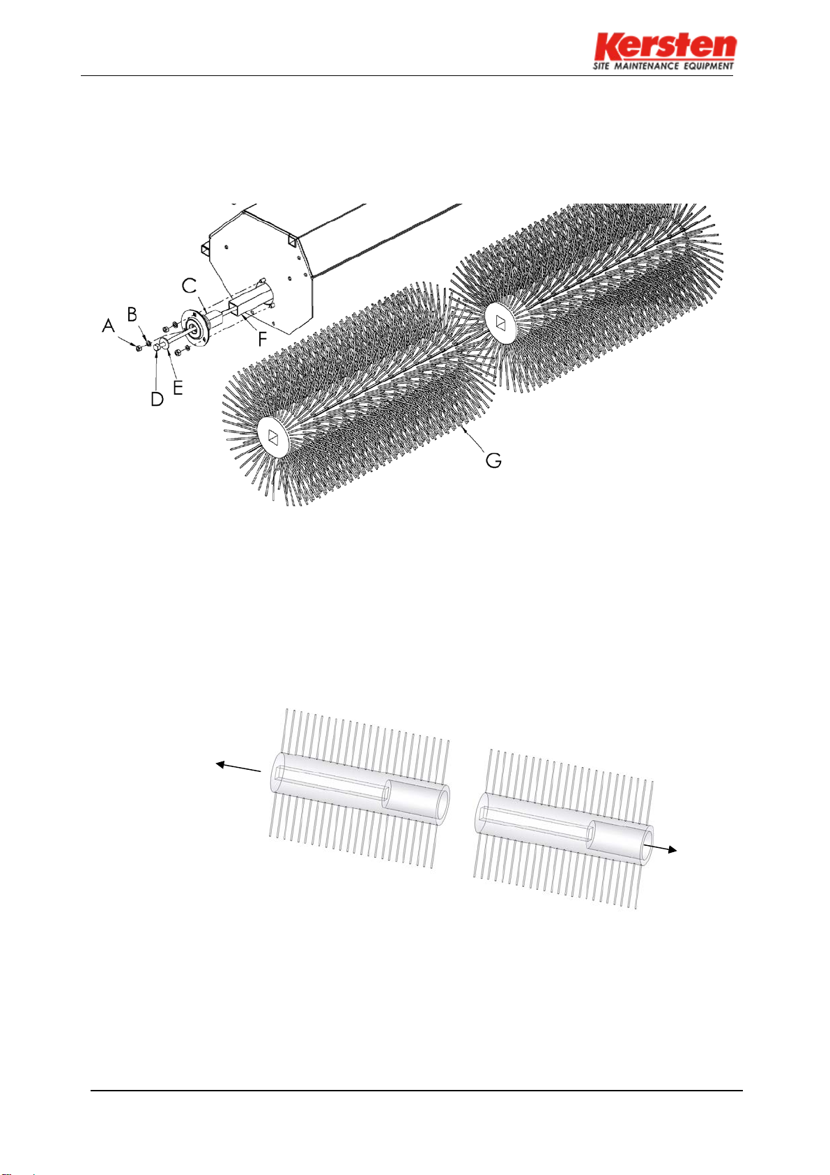
Installing the sweeping roller
9.6
Installing the sweeping roller
•
In the direction of travel on the right, remove the tension rod (D) with the K-washer (E) from the
sweeper's basic housing.
•
Loosen the three nuts (A) with the respective spring ring (B) and pull out the drive stub (C) with
bearing shells.
•
Remove the drive tube (F), insert the sweeper broom [two-piece] (G) into the machine so that
the 145 mm round hole to the right points to the hydraulic motor, see Fig.7a.
•
Then reassemble the drive tube in reverse order with the drive stub and the tension rod.
Broom sweeper
two-piece
right
Hydraulic
engine left
Fig.7a
Fig.7

Technische Daten
19
10 Technical data
10.1
Sweeper
Type
KM 10037 H-FKDR
KM 11537 H-FKDR
KM 12537 H-FKDR
Overall width
1070 mm
1220 mm
1320 mm
Working width a
1000 mm
1150 mm
1250 mm
Total width at
inclination
1075 mm 1195 mm 1325 mm
Working width at
inclination
866 mm 976 mm 1086 mm
Sweeping rollers Ø
370 mm
370 mm
370 mm
Drive
hydraulic
hydraulic
hydraulic
Mass
46 kg
49 kg
52 kg
Hydraulic oil
Avia N 46
Avia N 46
Avia N 46
Amount of oil
ca. 4.5 Liter
ca. 4.5 Liter
ca. 4.5 Liter
10.2
Dimension sheet
Dimensions for working with a can be found in Table 10.1.
Fig.8
10.3
Scope of delivery as standard
•
Combi sweeping roller with poly-twist trim, five-row
•
KM 10037 H-FKDR; KM 11537 H-FKDR; KM 12537 H-FKDR
10.4
Additional equipment
•
Dirt collector
•
Rubber splash flap
•
Water blaster
•
Further sweeping rollers on request, see spare parts list
•
Attachment side brush
-Reserve technical changes! -
This manual suits for next models
2
Table of contents
Other Kersten Farm Equipment manuals


