Kesla 2014 User manual

(a translation from the original version)
KESLA 2014 GB 2018 10
TIMBER HANDLING CRANE
2014
2014T
USER MANUAL
MAINTENANCE
SPARE PARTS


EC DECLARATION OF CONFORMITY FOR MACHINERY
Manufacturer: Kesla Oyj
Kuurnankatu 24, FI-80100 JOENSUU, FINLAND
Name and address of the person authorized to compile the technical file:
Riku Väyrynen
Kuurnankatu 24, FI-80100 JOENSUU, FINLAND
Herewith we declare that
Timber handling crane KESLA 2014, 2014T
Serial number:_____________________
is in conformity with the relevant provisions of the Machinery Directive (2006/42/EC)
is in conformity with the provisions of the following other EC-Directives
2014/30/EC
And furthermore, we declare that
the following (parts/clauses of) European harmonised standards have been used
SFS-EN ISO 12100
SFS-EN-12999
Place, time: Joensuu 10/1/2018 Signature: ____________________
Managing Director Simo Saastamoinen
(a translation from the original version)
Kesla Oyj Registered office: Joensuu Business ID 0168715-8
Kesälahti factory Metsolantie 2 59800 KESÄLAHTI tel. +358 207 862 841 fax. +358 13 6100 322
Joensuu factory Kuurnankatu 24 80100 JOENSUU tel. +358 207 862 841 fax. +358 13 6100 523


CONTENTS
EC DECLARATION OF CONFORMITY
1INTRODUCTION ..................................................................................................1
1.1GENERAL INFORMATION............................................................................................... 2
1.1.1Storing the manual..................................................................................................... 2
1.1.2Manual contents ........................................................................................................ 2
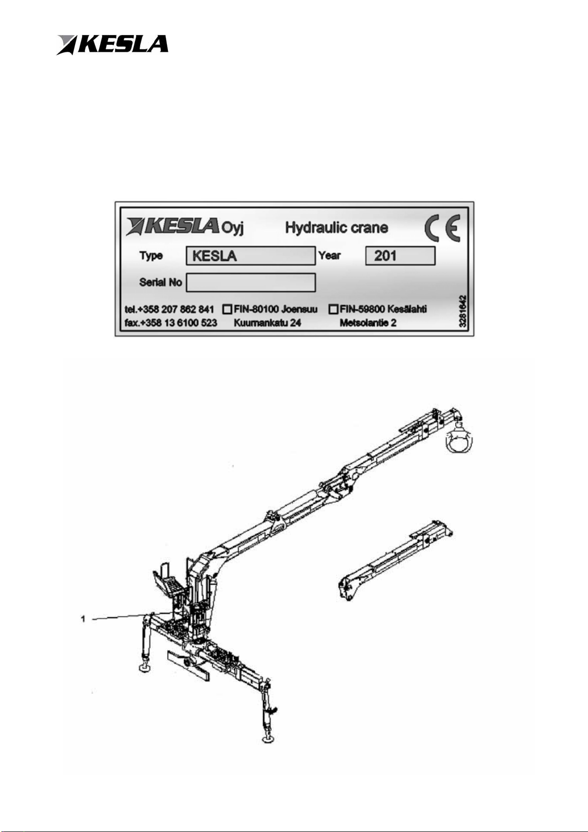
1.2MACHINE PLATE ............................................................................................................. 3
1.3PURPOSE OF THE CRANE............................................................................................. 4
1.4RECOMMENDED OPERATING CONDITIONS................................................................ 4
1.5PROHIBITED USAGE AND CONDITIONS OF USE........................................................ 4
1.6GENERAL WARRANTY TERMS FOR KESLA PRODUCTS............................................ 5
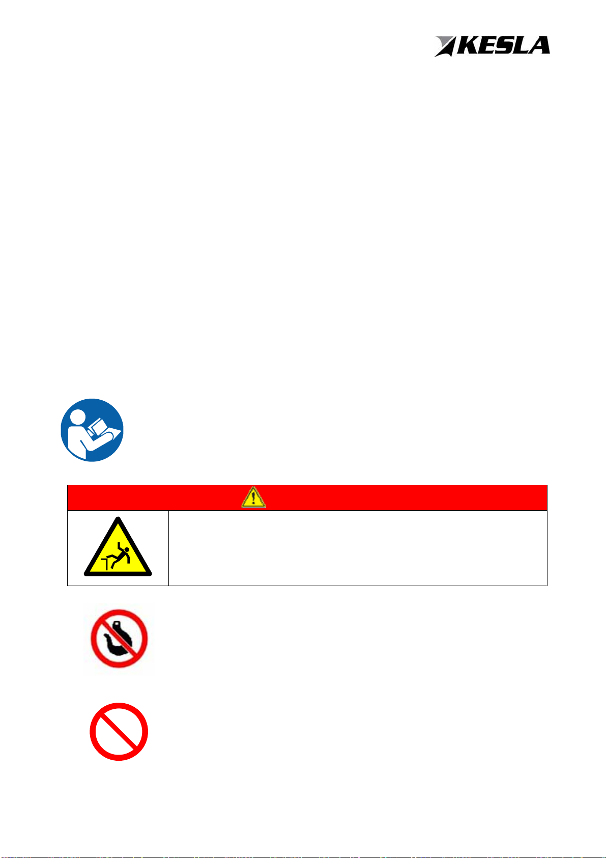
1.7THE INFORMATION AND WARNING SYMBOLS IN THE MANUAL............................... 7
1.7.1Warning symbols....................................................................................................... 7
1.8CONTACT INFORMATION............................................................................................... 7
2SAFETY INSTRUCTIONS....................................................................................8
2.1GENERAL SAFETY INFORMATION................................................................................ 8
2.2THE BIGGEST SECURITY RISKS WHEN OPERATING AND MAINTAINING THE
CRANE............................................................................................................................. 9
2.3SAFETY INSTRUCTIONS .............................................................................................. 10
2.3.1Danger zones during use......................................................................................... 11
2.3.2Safety devices ......................................................................................................... 12
2.3.3Emergency stops..................................................................................................... 13
2.3.4Priorities and dimension drawings........................................................................... 13
2.3.5Caution and warning signs on the crane ................................................................. 14
2.4HYDRAULIC SYSTEM.................................................................................................... 19
2.5SAFETY INSTRUCTIONS FOR HANDLING CHEMICALS ............................................ 20
2.6WELDING THE CRANE.................................................................................................. 21
2.7INSTALLING ACCESSORIES AND MODIFYING THE DEVICE STRUCTURE............. 21
2.8SAFETY PRECAUTIONS ON THE ROAD ..................................................................... 22
2.9USER’S MANUAL KESLA CE -EQUIPMENT................................................................. 23
3ABOUT THE CRANE .........................................................................................26
3.1CRANE'S MAIN COMPONENTS.................................................................................... 26
3.2CRANE OPERATION...................................................................................................... 27
3.3CRANE EQUIPMENT OPTIONS.................................................................................... 27
3.3.1Basic crane models ................................................................................................. 27
3.3.2Crane accessories................................................................................................... 28
4COMMISSIONING..............................................................................................29
4.1SAFETY INSTRUCTIONS FOR THE CRANE’S COMMISSIONING.............................. 29
4.2PREPARATIONS FOR CRANE COMMISSIONING....................................................... 29
4.3CRANE MOUNTING....................................................................................................... 30
4.3.1Installation to a movable stand behind a truck......................................................... 31
4.3.2Installing the crane behind the cabin....................................................................... 32
4.3.3Installation of the rotator and its hoses in Keslink:................................................... 33
4.3.4Hose connections.................................................................................................... 34
4.4INSTALLER..................................................................................................................... 35
4.4.1Safety instructions ................................................................................................... 35
4.5INSPECTIONS................................................................................................................ 35
4.5.1Commissioning inspection....................................................................................... 35
4.5.2Warranty service...................................................................................................... 35
4.5.3Periodic inspections................................................................................................. 36
4.5.4Thorough periodic inspection................................................................................... 36
4.5.5The crane's daily inspection..................................................................................... 36
4.6INSTRUCTIONS ON HOW TO CALCULATE THE CRANE'S STANDING STABILITY.. 37
4.7INSTRUCTIONS ON HOW TO DETERMINE EXPERIMENTALLY THE CRANE'S
STANDING STABILITY .................................................................................................. 38
4.7.1Safety instructions ................................................................................................... 38
4.7.2Test conditions......................................................................................................... 38

CONTENTS
4.7.3Performance of test ................................................................................................. 38
5WORKING WITH THE CRANE ..........................................................................39
5.1GENERAL INFORMATION............................................................................................. 39
5.1.1Safety instructions ................................................................................................... 39
5.2THE CRANE'S OPERATING PRINCIPLE ...................................................................... 40
5.3WORKING METHOD...................................................................................................... 40
5.3.1Special Safety Instructions ...................................................................................... 40
5.3.2Practice.................................................................................................................... 41
5.4CRANE COMMISSIONING............................................................................................. 41
5.5EMERGENCY STOP MEASURES................................................................................. 43
5.5.1Tipping hazard......................................................................................................... 43
5.5.2Emergency stop in case of rupture of hoses ........................................................... 43
6ADDITIONAL INSTRUCTIONS..........................................................................44
6.1WAREHOUSING AND STORAGE.................................................................................. 44
6.1.1Start-up after storage............................................................................................... 44
6.2ROAD TRAFFIC.............................................................................................................. 45
6.3REMOVAL OF A CRANE FROM USE............................................................................ 45
7TROUBLESHOOTING........................................................................................46
7.1.1Safety instructions ................................................................................................... 46
8MAINTENANCE INSTRUCTIONS......................................................................47
8.1SAFETY INSTRUCTIONS .............................................................................................. 47
8.2GENERAL MAINTENANCE INSTRUCTIONS................................................................ 47
8.3DAILY INSPECTIONS..................................................................................................... 48
8.3.1Hydraulic hoses and pipes....................................................................................... 48
8.3.3Shaft locks............................................................................................................... 48
8.3.4Hydraulic system ..................................................................................................... 49
8.4MAINTENANCE SCHEDULE.......................................................................................... 49
8.5TURNING DEVICE.......................................................................................................... 50
8.5.1Lubrication of the turning device.............................................................................. 50
8.5.2Positions of the turning device................................................................................. 51
8.5.3Opening of the turning device.................................................................................. 52
8.6THE BOOM..................................................................................................................... 53
8.6.1Lubrication of the lifting boom.................................................................................. 53
8.6.2Lubrication of the transfer booms............................................................................ 53
8.6.3Opening of the transfer booms................................................................................ 54
8.6.4Adjustment of the tightening of the chains (two - extension models)....................... 54
8.6.5Adjustment of the lateral clearings........................................................................... 55
8.6.6Adjustment of the vertical gap (one and two - extension models)........................... 55
8.6.7Changing of the sleeve bearing............................................................................... 56
8.6.8Adjustment of the grapple hanger brake.................................................................. 56
8.7THE HYDRAULIC SYSTEM............................................................................................ 57
8.7.1Requirements set for a good hydraulic oil ............................................................... 57
8.7.2Impurities in oil......................................................................................................... 58
8.7.3Avoid any impurities in the oil.................................................................................. 58
8.7.4Biodegradable hydraulic oils.................................................................................... 59
8.7.6Performance of oil change....................................................................................... 60
8.8PRESSURE MEASUREMENT........................................................................................ 61
8.8.1Measurement........................................................................................................... 61
9LUBRICATION ...................................................................................................62
9.1LUBRICATION TARGETS.............................................................................................. 62
9.1.1Oils and Lubricants.................................................................................................. 64
10ELECTRICAL DIAGRAMS.................................................................................65
10.1POWER SUPPLY CABLE CONNECTIONS................................................................... 70
11ANNEXES, TECHNICAL SPECIFICATIONS ETC.............................................71

GENERAL INFORMATION
1
DEAR CUSTOMER,
Thank you for choosing a KESLA product and we wish you success in your work. We ask you to
carefully read this manual as good knowledge of the machine's operation and meticulous man-
agement result in the best occupational safety conditions and the machine's productivity from day
to day. It is important that you have understood and complied with every section of this book. In
case of doubt please contact your dealer. You can also provide feedback to Kesla using the feed-
back form at the end of this manual or at www.kesla.fi.
1 INTRODUCTION
1. Read the instructions first. A prerequisite of the crane's use is a good understanding of its
safety and operating instructions.
2. Check the basic unit's compatibility with regard to hydraulics and standing stability.
3. Follow the installation instructions and, if necessary, ask more information from your dealer
or from the factory.
4. Carry out legally required inspections.
5. Practice makes perfect.
6. Always work with caution.
7. Make a slow full-scale operating movement back and forth with all the loader's cylinders to
make the gaskets more flexible.
8. Grease often and only a little bit rather than rarely and a lot.
9. Cleanliness is the most important thing in hydraulic systems.
10. Pre-loading oil: TEBOIL ECO 46
11. Repair even small defects before they can cause more serious damage.

GENERAL INFORMATION
2
1.1 GENERAL INFORMATION
This is a machine-specific instruction manual for the KESLA crane to be supplied with the crane.
This manual is intended for persons who have previous experience with the use of timber cranes.
Please read and understand the operation, maintenance, and safety instructions
before operating or servicing the crane. Operation, maintenance and adjustment
may only be carried out by people qualified for operating and servicing the specified
device. Lack of information on the device's operation and characteristics can cause
serious injury or death.
1.1.1 Storing the manual
This manual is an essential part of the product and must be maintained intact throughout the
product's service life. If any changes are made to the crane, they should be added to this manual.
Keep your manual clean and easily accessible. If the crane is sold, the manual must be handed
over to the new owner.
1.1.2 Manual contents
The operating instructions contain the following information:
General information about the manual's purpose and content, instructions on how to read
the manual, as well as a request to provide feedback and report any possible errors.
Safety instructions
Daily inspections
Operating instructions
*) The asterisk notifies information on the subject issue.
-) The dash indicates necessary / possible steps to be taken.
* All descriptions, instructions and specifications in this manual are based on the latest information
about the machine's structure on the date the manual was printed. The product is being continu-
ously developed and, therefore, the manufacturer reserves the right to change product specifica-
tions without prior notice.
* If machine malfunctions occur, the problem and its probable cause can be clarified and corrected
on the basis of the table. If you are unable to repair the machine yourself, please contact your
dealer or a service workshop authorized by the dealer.

GENERAL INFORMATION
3
1.2 MACHINE PLATE
When ordering spare parts or requesting repair instructions, communicate to your dealer or re-
pairman the information on the machine plate. This procedure will speed up getting help in case of
malfunction or ensure that you receive the correct parts as fast as possible.
Write the machine plate information to the machine plate's image below.
Machine plate location:

GENERAL INFORMATION
4
1.3 PURPOSE OF THE CRANE
KESLA timber handling crane is designed for timber loading in contracting work. The crane is also
suitable for loading scrap, sand, fertilizer, etc. when grapples fit for purpose are being used. Using
the crane for lifting persons is prohibited!
1.4 RECOMMENDED OPERATING CONDITIONS
* If work is carried out at low temperature, let oil circulate for a while through the valve system with
a low flow. Then slowly perform all the operating movements, back and forth, in order to make the
gaskets more flexible before they receive maximum pressure. The crane's lowest recommended
operating temperature is - 25°C.
* It should be noted that in lower temperatures hydraulic gaskets wear faster and the probability
that hoses and steel structures become more susceptible and steel structure's probability of brittle
fracture increases. When working in temperatures below - 25°C, it is preferable to lift smaller than
normal loads in order to avoid unnecessary damage.
* Similarly, in very warm conditions one should ensure that the hydraulic oil does not overheat
(<75°C). A too high oil temperature may cause damage to the gaskets and it also reduces oil life.
1.5 PROHIBITED USAGE AND CONDITIONS OF USE
The KESLA crane is designed for timber loading and it can be used
only by a person familiar with its use.
It is forbidden to use the crane without having studied its use and
safety instructions!
Operation with hooks is not allowed!
Use of the crane for towing is prohibited!
DANGER
RISK OF FALLING
Using the crane for lifting of persons is prohibited!

GENERAL INFORMATION
5
CAUTION
Using a crane for compacting the loaded trailer and using a grap-
ple as a hammer to level out stacks of wood is forbidden!
CAUTION
Any use of a damaged or defective crane is prohibited!
1.6 GENERAL WARRANTY TERMS FOR KESLA PRODUCTS
Kesla Oyj guarantees that the products they sell are free of defects and provides the
following warranty for any problems that might appear in workmanship or materials:
1. The warranty period is valid starting from the day the product is installed and covers only
new products sold to their first owner.
-For truck- and stationary installed loaders the warranty period is 2000 working
hours or 12 months. The main components of the timber loader frame structure such
as the boom, stabilizers and slew mechanism are warranted for 24 months from the
date of delivery from factory.
-For forest machine cranes and harvester heads the warranty period is 2000 working
hours or 12 months.
-For chippers the warranty period is 1000 working hours or 12 months.
-For tractor-mounted timber trailers and loaders the warranty period is 12 months from
the date of delivery to the customer. However, the warranty is valid max. 18 months
from the date of delivery from the Kesla factory.
-For spare parts the warranty period is 6 months from the date of purchase.
-Kesla shall supply spare parts, produced by Kesla, for a period of ten (10) years, af-
ter the manufacturing of the Product has been stopped.
-Warranty will be void when either working hours or calendar time of warranty period
is filled.
2. Repair work under warranty is done during normal business hours only by Kesla Oyj facto-
ry authorized repair workshops or by Kesla Oyj authorized service repairman working ac-
cording to their standard working schedule.
3. Kesla Oyj reserves the right to approve and authorize any part or work claimed under war-
ranty.
4. The warranty stipulates that crane installation registration records to be properly filled out
and returned to Kesla Oyj within 30 days of installation. The registration record contains
the assurance that the new owner/user has been familiarized with the instruction manual.

GENERAL INFORMATION
6
In order for the warranty to be valid the bill of delivery for loaders/trailers and the initial
registration documents for harvester heads must be returned to Kesla Oyj. Furthermore
the warranty requires first service to be carried out on cranes within 30 days of initial ac-
tive use.
5. Reimbursement applications for repair work must be filled out by the buyer or the author-
ized service repair workshop and returned to Kesla Oyj within 30 days from the date of
damage. Damaged parts should be marked with both the customer’s and machinery’s in-
formation and may be requested to be returned to Kesla Oyj for inspection. Kesla Oyj will
bear the cost of normal shipping charges for the returned parts if the matter has been
agreed on in advance with Keslas warranty handling personnel. The warranty period for
the exchanged part is valid to the end of the original warranty of the machine.
6. In case the warranty demand concerns a faulty part that has been taken apart from a
Kesla product, it can be replaced with a similar functioning part free of charge by Kesla
Oyj spare parts warehouse, at an authorized service workshop or by Kesla Oyj authorized
service repairmen. The warranty covers defects arising in raw material, structure or manu-
facturing. The defected part will be replaced with a new or reconditioned part from Kesla
Oyj.
7. The warranty does not cover parts which normally wear out and need to be regularly re-
placed such as filters, oil, hoses, gaskets, belts, skid bearings and glide pads or any simi-
lar.
8. The warranty does not cover faults resulting from:
-Non-compliance with proper use and/or safety issues as mentioned in the product
manual
-Improper or non-sufficient installment or service
-Normal wear and tear
-Accidents
-Overloading
-Impurities in oil or in hydraulic system
9. The customer bears financial responsibility for costs arising from fulfilling warranty re-
quirements such as travel and accommodation costs for repair personnel, fees for trans-
porting equipment or components, overtime or other similar costs.
10.If machinery breaks down, Kesla Oyj bears no responsibility for damages caused by ma-
chinery to property or persons. Furthermore, Kesla Oyj bears no responsibility for financial
loss occurring in down time (for example, losses arising from wages or transportation
fees).
11.Attachments or components supplied to Kesla Oyj by sub-contractors are quaranteed only
according to the warranty terms given by the supplier.
12.The warranty will be considered either patially or entirely invalidated if repair or mainte-
nance carried out by the owner/user are done improperly, if unsuitable, non-compatible or
foreign parts are installed, if modifications or changes to the product or hydraulic equip-
ment are made without the a written permission of Kesla Oyj or if hydraulic system is ad-
justed exceeding allowed tolerances or reference values.
13.In addition to the above mentioned terms there may be more detailed product-specific war-
ranty terms which are written into the user manual of each product.

GENERAL INFORMATION
7
1.7 THE INFORMATION AND WARNING SYMBOLS IN THE MANUAL
The warnings in this manual have been divided into three classes as follows.
DANGER indicates a hazardous situation which, if realized, will
result in death or serious injury.
WARNING indicates a hazardous situation which, if realized,
could result in death or injury.
CAUTION indicates a situation which, if realized, may result in
property damage.
1.7.1 Warning symbols
Warning symbols are used in the manual to describe a danger, prohibited action or required action
(order).
Danger
A black symbol inside a yellow triangle describes a danger
Prohibition
Black symbol in a red circle describes a prohibited action
Direction sign
White symbol on blue background describes an action that must be per-
formed in order to avoid danger.
1.8 CONTACT INFORMATION
www.kesla.com
SPARE PART ORDERS spare.parts@kesla.com
SERVICE AND WARRANTY ITEMS after.sales@kesla.com
Spare parts and services tel. +358 40 709 2208

SAFETY INSTRUCTIONS
8
2 SAFETY INSTRUCTIONS
2.1 GENERAL SAFETY INFORMATION
Please read and understand the operation, maintenance, and safety in-
structions before operating or servicing the cranes. Operation, mainte-
nance and adjustment may only be carried out by people qualified for op-
erating and servicing the specified device. Lack of information on the de-
vice's operation and characteristics can cause serious injury or death.
The user must always wear safety equipment
such as a safety helmet, protective clothing, safety footwear, hearing pro-
tection, safety glasses and other protective equipment in accordance with
the provisions required for work.
If the machine has a main power switch, open it before leaving the ma-
chine unattended.
Follow the precautionary and operating instructions attached to the machine. This will
avoid accidents when working with crane.
Plan your work carefully in advance in order to avoid any possible damage and acci-
dents. The operator must master the functions of the device prior to its introduction.
When working with the crane, make sure that the platform that supports the crane is so
sturdy that there is no danger of the crane falling.
Never start a job you are not trained to do and for which you have no authorisation.
Notify the crane's operator about any maintenance and repair work being started.
When working ensure that there are no people in the crane's danger zone.
When starting the drive unit, the hydraulic power must be disconnected from the device.
Do not leave the running drive unit alone even for a moment.
Before any maintenance and repairs to the crane, make sure the crane is on a stable
surface. Turn off the vehicle's engine, turn off the hydraulic pressure from the device,
set the parking brake and remove the ignition key from the ignition switch.
Mark the construction site with signs, if necessary.
Do not cede the crane to anyone until you have ensured that the person is adequately
informed of the machine's operation and safety instructions.
The crane's use is forbidden when under the influence of alcohol or other intoxicating
substances.
Use great caution when attaching or detaching the crane from the drive unit or trailer
truck.
Clean and wash the crane regularly and always before starting any maintenance or re-
pair works.
Never use a broken crane as there is risk of accident in case the structure suddenly
fails.

SAFETY INSTRUCTIONS
9
2.2 THE BIGGEST SECURITY RISKS WHEN OPERATING AND MAIN-
TAINING THE CRANE
WARNING
DANGER OF HIGH-PRESSURE LIQUID JETS!
High-pressure jets of oil can shoot out of faulty hydraulic hoses
and cause serious injury when coming in contact with skin.
Check the hoses condition regularly and replace the
worn/damaged with new ones.
In case of an accident, please seek immediate medical attention.
DANGER
PINCH HAZARD
Hands or other parts of the body can be trapped inside the de-
vice's framework or under the load resulting in death or serious
injury.
Use great caution when working in the vicinity of the machine.
Always wear appropriate (CE-approved) safety equipment.
Do not work the machine's danger area unless it is turned off.
DANGER
DANGER OF ELECTRICAL SHOCK!
Touching high-voltage wires will result in death or serious injury.
When using the device, please follow the safety distances be-
tween live wires.

SAFETY INSTRUCTIONS
10
Noise emission exposure made by the machines can cause weak-
er hearing or even worse hearing loss.
The noise level at the work site depends on the sound proofing of
a the truck or any other machinery's sound proofing, as well as
the from the position of the control valves.
The manufacturer recommends when needed the use of appropri-
ate and effective personal hearing protection.
2.3 SAFETY INSTRUCTIONS
* The crane's operator is responsible for operating the crane safely.
* The user must be at least 18 years old and his/her hearing and vision must be so good that it is
safe to work.
WARNING
RISK OF FALLING
When rising to the control position and leaving it, use the ma-
chine's steps and handholds so that both hands and one foot or
one hand and both legs have stabilize.Check the hoses condition
regularly and replace the worn/damaged with new ones.
Do not jump!
* The floor at the control position has to be kept empty of loose objects.
* There should not be any other persons at the control position.
* Adjust the seat and controls and keep the windows clean.
* Wear a seat belt, if possible.
* Check that the crane has been properly mounted
* Use great caution when attaching or detaching the crane from a vehicle.
DANGER
TIPPING HAZARD!
Instability of the device may cause its unexpected movement that
could result in death or serious injury.
Never exceed the maximum slope angles when parking or operat-
ing the machine.

SAFETY INSTRUCTIONS
11
- the surface must be sufficiently strong and steady.
- rotation of the stabilizer leg must be prevented with a locking pin (against tipping hazard)!
- check that the rear mounting bracket has been locked to the vehicle with a chain.
* Always connect the return hose before the pressure hoses. Make sure that it has been con-
nected; otherwise the control valve may become damaged.
*After installation there could be air in the hydraulic system which causes sudden and uncontrolla-
ble movements. Remove the air by brining all the cylinders carefully to the extreme positions 4-5
times.
*Check before switching on the pressure that all the crane’s control levers are in the middle posi-
tion and that they also return to the middle position.
*Always apply parking brakes for the time of loading. If necessary, place blocks in front of wheels.
*Stabilizer legs are operated from a valve attached to the base or from the control position by re-
mote control.
* Spread out the Stabilizer legs as wide as possible to achieve good standing stability. If this is not
possible, start loading with small loads.
*The stabilizer legs are fitted with pressure-controlled check valves, so they hold in case of a pos-
sible overload or hose failure. The stabilizre legs are prevented from turning by pin locking, if nec-
essary. (For example, a stand-mounted crane is removed from the truck to its stabilizer legs). Pin
locking cannot be used during working.
*Please note that when the load increases, most of the weight goes to the stabilizer legs because
the truck springs have been lightened by stabilizer legs. As a result, it is recommended to shorten
the stabilizer legs in the mid of loading, in which case the weight shifts to the truck wheels.
* Avoid loading on a sloping surface. If this is not possible, use extreme caution and lift small loads.
When loading uphill, please remember that the pressure relief valve of reversing cylinders can be-
come overloaded and the load can escape downhill and cause an incident.
* The aggregate's standing stability is at its weakest when the load space is empty. When the ag-
gregate begins to fall, lower the grapple immediately to the ground. Do not drop the load by open-
ing the grapple.
2.3.1 Danger zones during use
* The label is big, attached to both sides of the hinged boom and indicates the danger zone during
operation.
Make sure that there are no unauthorized persons in the danger
zone during loading.

SAFETY INSTRUCTIONS
12
* The crane is supplied with a label regarding safety distances from live wires. The label must be
affixed to a location where it is easily readable when using the crane.
* The label is placed to the control position and strictly forbids the presence of people in the danger
zone during lifting (danger zone 25 m).
2.3.2 Safety devices
* The crane's hydraulic system is equipped with various safety valves in order to ensure safe work-
ing.
* Changing the settings of valves without a written permission is strictly prohibited.
* The pump circuits of the truck's hydraulic system must be equipped with pressure relief valves
with opening pressure at least twenty (20) bars higher than the opening pressure of the crane's
main release.

SAFETY INSTRUCTIONS
13
1. The main release prevents the working pressure to rise too
high. There is one on each pressure control valve over each
pressure connection. If the pressure of oil coming to the control
valve exceeds the set value, oil will be discharged to the tank
channel until the set pressure level has been reached once
again.
2. Cylinder-specific pressure relief valves prevent the pressure
to rise too high in different cylinders. If the cylinder exceeds the
set pressure value, oil will be discharged from the cylinder
through the pressure relief valve until the permitted pressure
value has been reached.
3. Throttle check valves are used in swing, lift, and transfer cyl-
inders. They regulate the travel speed of the booms so that the
speed is adequate and the corresponding cylinders get enough
filling oil from the pump.
* NOTE! The check valve's adjustment should be done
when unpressurised(Pump has been switched off); the valve
can become damaged.
4. The stabilizer legs are equipped with pressure-controlled
check valves (lock valve). They prevent the legs from collapsing
in case of a possible overload or hose failure.
5. A swing, lift, and transfer cylinder can be equipped with an
overcenter valve, if necessary. It locks the load into the desired
position and prevents the load from falling in case the hose
breaks. The load’s descent takes always place in a controlled
way.
2.3.3 Emergency stops
he crane's control system must be equipped with a STOPswitch located in the crane's control posi-
tion. It can be used to cut off crane's oil supply (e.g. by an electrically controlled valve) or, alterna-
tively, the electric current to the pilot-operated control valve. Also the stopping of the drive unit is
considered as a STOP- operation, if it can be done from the control position.
2.3.4 Priorities and dimension drawings
More detailed device-specific information can be found in the booklet's APPENDIXES (10)

SAFETY INSTRUCTIONS
14
2.3.5 Caution and warning signs on the crane
The crane has warnings and instructions attached to various spots, regarding the danger or in-
structions related to its use. By following them you can avoid accidents and machine breakdowns.
If the machine's warning labels become detached or torn, they must be immediately repaired.
LABEL NO. 1 DANGER ZONE LABEL
* The label is big, attached to both sides of the hinged boom and indicates the danger zone during
operation.
.
* Staying in the danger zone during lifting is strictly prohibited.
This manual suits for next models
1
Table of contents
Other Kesla Construction Equipment manuals
Popular Construction Equipment manuals by other brands

Tadano
Tadano GR-750XL-2 manual

JLG
JLG GRADAL 522 Owner's/operator's manual

Dexter Laundry
Dexter Laundry HCM450B Safety instructions

Bramley
Bramley 42 AB2 Operating instructions & parts list

Global Manufacturing
Global Manufacturing GWE Series operating instructions

Scheppach
Scheppach HP1200S Translation of original instruction manual