1. Functional Description
This setpoint generator is an easy-to-
use microprocessor-controlled device
outputting current and voltage values.
Current: 0 ... 24 mA
Voltage: 0 ... 12 V DC.
Only one output can be used at a
time.
Three operating modes can be pro-
grammed:
– Standard setpoint function
– Manual ramp function
– Automatic ramp operation
Data backup for power failure
The programmed data is saved in an
EEprom; it remains saved even in
case of a power breakdown.
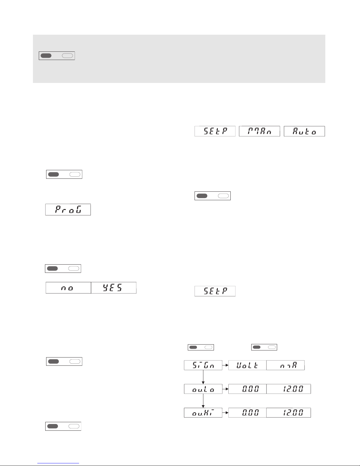
1.1 The SEtP Operating Mode
In this mode, the device is operated
in manual operation after program-
ming: a setpoint is input by means of
the keys. The value input here
directly in volts or mA, will be the
value output by the device.
If no other key is depressed within 3
seconds, the value input will be con-
sidered as the new setpoint and will
be output by the device.
1.2 The MAn Operating Mode
In this mode, the device is operated
in manual ramp operation after
programming: this operation is defi-
ned by means of 2 freely selectable
current or voltage values and by the
increment. During operation, press
the right key to increase the setpoint
by the increment programmed, press
the left key to reduce the setpoint by
this increment. In addition, the
device offers the possibility to apply
a scale factor to the setpoint output:
it is possible to display e.g. 10 (kg)
while 2 V are output. During operati-
on, the display alternates between
the output setpoint and the message
MAn.
1.3 The Auto Operating Mode
In this mode, the device is operated
in ramp operation after program-
ming: the automatic ramp function is
defined by means of a maximum of
20 current or voltage values which
are output automatically. The ramp
function can be either cyclic or
limited. A cycle can be programmed
in the range of 0.1 s ... 999.9 s or
0.1 min .... 999.9 min. The automatic
ramp function is started with the
right key. It can be ended with the
left key. The automatic ramp function
can be stopped by activating the
Hold input. During operation, the dis-
play alternates between the output
setpoint and the message Auto.