GMDE GEatom 306KTL User manual

GMDE GEatom 306KTL
Global Mainstream Dynamic Energy Technology Ltd.
1
–GEatom306KTL
Three-phase Grid-Tied Battery Inverter
Version 1.1

GMDE GEatom 306KTL
Global Mainstream Dynamic Energy Technology Ltd.
2
Content
Prelude ..................................................................................................................... 4
1. Safety .......................................................................................................................... 5
1.1 How to Use This Manual.................................................................................................. 5
1.2 Safety Rules ..................................................................................................................... 5
1.3 Warning Notices Affixed to the Device ........................................................................... 6
1.4 Important Safety Information ......................................................................................... 6
1.5 Disposal ........................................................................................................................... 8
1.6 Exclusion of Liability ........................................................................................................ 8
2. Description .................................................................................................................. 9
2.1 General System Description ............................................................................................ 9
2.2 Description of the Device .............................................................................................. 10
2.3 Outside Dimension of the Device.................................................................................. 11
2.4 Technical Data ............................................................................................................... 12
2.4.1 DC Data................................................................................................................... 12
2.4.2 AC Data................................................................................................................... 12
2.4.3 General Data........................................................................................................... 13
3. Installation................................................................................................................. 14
3.1 Operation Sequence...................................................................................................... 14
3.2 Unpacking...................................................................................................................... 15
3.2.1 Packing List ............................................................................................................. 15
3.2.2 Unpacking the Device............................................................................................. 15
3.2.3 Identifying the Inverter .......................................................................................... 17
3.3 Mounting....................................................................................................................... 18
3.3.1 Assembly Site Requirements.................................................................................. 18
3.3.2 Mounting the Inverter............................................................................................ 18
3.4 Electrical Connection..................................................................................................... 20
3.4.1 Connectors.............................................................................................................. 20
3.4.2 DC Connection........................................................................................................ 21

GMDE GEatom 306KTL
Global Mainstream Dynamic Energy Technology Ltd.
3
3.4.3 AC Connection........................................................................................................ 21
3.4.4 Communication Interface Port............................................................................... 23
*3.4.5 Power Meter Installation...................................................................................... 25
4. LCD Display ................................................................................................................ 26
4.1 LCD Interface ................................................................................................................. 26
4.2 Menu Structure ............................................................................................................. 27
4.2.1 Main Menu ............................................................................................................. 27
4.2.2 Energy Menu Structure .......................................................................................... 28
4.2.3 Run Info Menu Display ........................................................................................... 29
4.2.4 Fault& Alarm Menu Display.................................................................................... 30
4.2.5 Setting Menu Display.............................................................................................. 30
4.2.6 “Inv Info.” Menu Display ........................................................................................ 30
4.3Settings........................................................................................................................... 31
4.3.1 Language Setting .................................................................................................... 32
4.3.2 Clock Setting........................................................................................................... 32
4.3.3 Password Setting .................................................................................................... 33
4.3.4 Battery Setting........................................................................................................ 34
4.3.5 Clear Data ............................................................................................................... 36
4.4 Fault, Warning and Historical Information Deleting ..................................................... 36
5. Troubleshooting......................................................................................................... 38
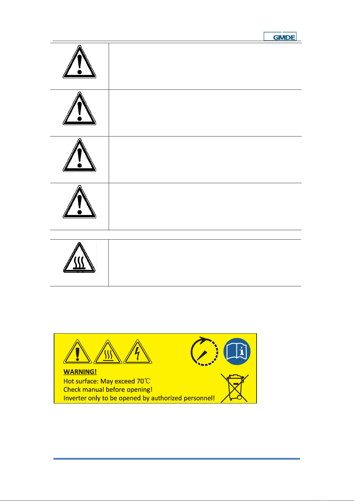
5.1Safety during Troubleshooting....................................................................................... 38
5.2 Faults ............................................................................................................................. 38
5.3 Fault Messages and Actions List.................................................................................... 38
5.4 Fault Acknowledgement................................................................................................ 41
5.5 Technical Service ........................................................................................................... 42
6. Maintenance.............................................................................................................. 43
6.1 Before Maintenance...................................................................................................... 43
6.2 Visual Inspection............................................................................................................ 43
6.3 DC Switch Yearly Maintenance...................................................................................... 43
7. Contact ........................................................................................................... 44

GMDE GEatom 306KTL
Global Mainstream Dynamic Energy Technology Ltd.
4
Prelude
Published by
Legal Disclaimer
Copyright
Global Mainstream Dynamic Energy Technology Ltd. (GMDE)
Room 604-605, Tongpu Road No.1220, Putuo District, Shanghai,
P.R.China.
Tel: +86 21 60710809 Fax: +86 21 61730300
www.global-mde.com
All information in this documentation has been compiled and checked
with most care. Despite of this, faults or deviations cannot be
completely excluded. We assume no liability and are hereby
acknowledged.
The relevant up-to-date version can be obtained from
www.global-mde.com
The details of this documentation are the property of GMDE.
Using and publicizing this documentation, even if only in parts require
the written consent of GMDE.
Read this user manual before you start
Thank you for purchasing our products, this battery inverter is highly reliable and efficient due to its
convenient design and excellent quality. This three phase device is IP65 rated for dusty or humid
environments and is suitable for outdoor application.
If you are reading the electronic version of the manual, please note that you can click the content to
find information you want quickly. All the characters which contain underline are clickable. A phrase
named ‘Back to Top’at the bottom of each chapter can help you back to the first page rapidly.
Before using this device, please ensure that you have read this manual including installation and safety
operation carefully.
If you have any difficulties during installation or operation, please refer to this manual or send email to
service@global-mde.com,we will help to solve your problems as soon as possible.
Back to Top

GMDE GEatom 306KTL
Global Mainstream Dynamic Energy Technology Ltd.
5
1. Safety
1.1 How to Use This Manual
Please read the safety instructions in this manual first. Throughout the manual it is assumed that the
reader is familiar with AC and DC installations and knows the rules and regulations for electrical
equipment and for connecting it to the utility AC grid. It is especially important to be familiar with the
general safety rules for working with electrical equipment.
1.2 Safety Rules
General introduction
These safety-related guidelines use the following ANSI notations to describe the various levels of
danger:
Death or severe personal injury will occur.
DANGER
Death or severe personal injury may occur.
WARNING
Personal injury or material damage may occur.
CAUTION
Explanations
Electric Shock!
Do not open the device! Dangerous voltage may still be applied inside the
device even after it has been switched off.
Electric Shock!

GMDE GEatom 306KTL
Global Mainstream Dynamic Energy Technology Ltd.
6
High leakage current!
Make absolutely sure you establish connection to ground before connecting
the device to the supply circuit!
WARNING
Health risk!
Health risk for persons with cardiac pacemakers, metallic implants, or
hearing aids in the immediate vicinity of electrical equipment!
WARNING
Risk of improper handling!
Personal injury by crushing, shearing, cutting, or striking.
CAUTION
Cancellation of the operating license!
If the GMDE inverter is operated with a wrong country code, the electric
supply company may cancel the operating license.
CAUTION
Hot Surface!
Surfaces of the housing can be hot! Risk of injury! Risk of burns.
The housing top and the heat sinks may have a surface temperature of 70°C .
Hot Surface!
1.3 Warning Notices Affixed to the Device
1.4 Important Safety Information
The following operating and maintenance instructions must be read before installing, operating or

GMDE GEatom 306KTL
Global Mainstream Dynamic Energy Technology Ltd.
7
maintaining the inverter.
Before installation:
Check for damage to inverter and package. If you are in doubt, please contact us or the distributor
before installing the inverter.
Before connecting the battery packs to the inverter, check the voltages and ensure that they are
within the limits of the GMDE inverter specifications. Failure to observe these specifications could void
your warranty.
Installation:
Only trained and qualified personnel familiar with local electrical codes may work with the electrical
installations. For optimum safety, please follow the steps described in this manual.
Please keep in mind that the inverter has battery input and AC grid output.
Disconnecting the inverter:
Please refer to “Disconnecting for maintenance” in section 6.1. Note that wait at least 15 minutes
before proceeding, after disconnecting the battery inverter from AC grid and battery packs.
Operating the inverter:
Do not commission the device until the overall system complies with the application-specific national
rules and safety regulations.
The ambient conditions given in the product documentation must be observed.
The machine or installation manufacturer is responsible for compliance with the limit values as
prescribed in the national regulations.
Only persons who are trained and qualified for the use and operation of this device may work on the
device.
Maintenance and modification:
Only authorized personnel are allowed to repair or modify the inverter. To ensure optimum safety for
user and environment, only the original spare parts available from your supplier should be used.
Functional safety parameters:
Unauthorized changes of functional safety parameters may cause injury or accidents to people or
inverter. Additionally,it will lead to the cancellation of all inverter operating approval certificates.

GMDE GEatom 306KTL
Global Mainstream Dynamic Energy Technology Ltd.
8
1.5 Disposal
Please dispose the package and replaced parts according to the rules
applicable in the country where the device is installed.
Do not dispose the GMDE inverter with normal domestic waste.
1.6 Exclusion of Liability
GMDE Technology Ltd. will not be liable for any direct, indirect or consequential damages, losses,
costs or losses including without restriction any economic losses of any kind, any loss or damage to
property, any personal injury, any damage or injury arising from or as a result of misuse or abuse, or
the incorrect installation, integration or operation of the product. We disclaim any liability for direct or
indirect damages due to:
1. Improper installation or commissioning,
2. Modifications, alterations or repair attempts,
3. Inappropriate use or operation,
4. Insufficient ventilation of the device,
5. Non-compliance with relevant safety standards or regulations,
6. Flood, lightning, overvoltage, storm, fire (acts of nature).
We do not assume any liability for an incorrect setting of country code.
We reserve the right to make alterations that will improve the functioning of the device.
Back to Top

GMDE GEatom 306KTL
Global Mainstream Dynamic Energy Technology Ltd.
9
2. Description
2.1 General System Description
With GMDE GEatom series battery inverters, customers can easily retrofit existing PV system to PV
energy storage system as it is shown in below Figure 1 and Figure 2. GMDE battery inverter has open
interface and is capable of working with all grid-tied inverters. The energy management solutions of
the energy storage systems are described as solution 1 and solution 2.
Solution1: Integrated Energy Management Solution
Through RS485 cable, the battery inverter communicates with the power meter that is installed
between the AC grid and the customer load. With the power-related information sent from the power
meter, the battery inverter can automatically decide how to charge or discharge the connected
battery packs
Note that:
(1) In this solution, lead-acid batteries can be integrated into the energy storage system without BMS
(Battery Management System).
(2) If lithium batteries are adopted, an independent BMS is compulsory to maintain battery’s lifetime.
(3) The power meter used in this application must be confirmed by GMDE first since the integration
of communication protocol between power meter and GMDE battery inverter is required.
Figure 1 Integrated Energy Management Solutions
Solution2: External Energy Management Solution

GMDE GEatom 306KTL
Global Mainstream Dynamic Energy Technology Ltd.
10
Figure 2 External Energy Management Solutions
In this solution, a third party EMS (Energy Management System) is required. GEatom battery inverter
is connected to this EMS by RS485 communication cable. The EMS monitors and controls the start-up
and operation of both the PV and battery inverters.. GEatom battery inverter can work with all the
EMS units as long as the communication protocol is integrated. To request the detailed
communication protocol, please contact us at service@global-mde.com.
Note: Maximum Charging current, Maximum Discharging current, Discharging Stop Voltage and
Charging Stop Voltage should be set before commissioning to maintain battery’s lifetime. We
recommend user to set these parameters every time before activate the inverter. In solution1, these
parameters are set in LCD screen see 4.3.4 Battery Setting”. In solution2, these parameters are set by
external commands according to communication protocol through RS485 interface.
2.2 Description of the Device
The GMDE battery inverter is a three-phase transformerless inverter, mainly being applied to
charge/discharge the battery packs, which could help save client’s electricity bill by optimizing use of
energy.

GMDE GEatom 306KTL
Global Mainstream Dynamic Energy Technology Ltd.
11
6
2
15
4
3
Figure 3 GMDE GEatom306KTL
①One pair of battery input terminals, consisting of positive and negative terminals.
②Integrated DC switch (note this DC switch cannot be directly switch off when battery
inverter is run, please refer to “Section 3.1 Operation Sequence” for disconnecting the battery
inverter.)
③The GMDE battery inverter provides multiple communication options: RS485/D-USB.
④Heat is dissipated by the heatsink and fan equipped at the bottom of this device.
⑤One AC output connector, which connects to the AC grid. (Rated conductor size: Ø 4 mm2).
⑥320x240 pixels display screen, on which the operation information can be displayed.
2.3 Outside Dimension of the Device

GMDE GEatom 306KTL
Global Mainstream Dynamic Energy Technology Ltd.
12
Figure 4 Outside dimension of GMDE GEatom306KTL
2.4 Technical Data
2.4.1 DC Data
MODEL LIST
GEatom306KTL
BATTERY INPUT(DC)
Operating DC Voltage Range [Vdc]
200-800
Full Power Operating Voltage Range [Vdc]
300-700
Charging Upper Limit Voltage [Vdc]
Being adjustable according to actual battery packs
configuration, as long as not exceed the input voltage
range.
Discharging Stop Voltage [Vdc]
Number of battery input packs
1
Maximum Discharging Power [kW/string]
6
Discharging Current [A/string]
20
Maximum Charging Power [kW/string]
6
Charging Current [A/string]
20
Table 1 Specifications of GMDE GEatom306KTL-1
2.4.2 AC Data
MODEL LIST
GEatom306KTL
OUTPUT (AC)
Rated Output Power [kW]
6
Rated Output Voltage [Vac]
3N ~400
Normal Operating Voltage Range [Vac]
324-436, 437-460 (<10min.)
Rated Output Frequency [Hz]
50
Normal Operating Frequency Range [Hz]
47.55-51.45
Rated Output Current [A]
8.7
Max. Output Current [A]
9.5
Power Factor [λ]
[-0.95, 0.95]
Standby Power Consumption [W]
< 15
THDI (100% full power)
< 3%
DC current injection (Max.) [mA]
45
Table 2 Specifications of GMDE GEatom306KTL-2

GMDE GEatom 306KTL
Global Mainstream Dynamic Energy Technology Ltd.
13
2.4.3 General Data
MODEL LIST
GEatom306KTL
EFFICIENCY
Max. Charging/Discharging Efficiency
> 96.5% / > 96.5%
PROTECTION
DC disconnect & DC fuse
Standard VDE approved DC switch
GENERAL DATA
Operating Temperature Range [ºC]
-25 to 60 (> 45 derating)
Acoustic Noise [dB]
< 55
Enclosure Protection (IP)
IP65
Heat dissipation
Forced air cooling
Altitude [m]
< 2000 (no derating)
Weight [kg]
<26
Dimensions[W*H*D, mm]
408*548*231
Installation Mode
Wall-mounted
Humidity
< 95% RH
Communication
USB/RS485
Hazard substance restriction
Lead free, complied with RoHS GP2
LCD
Graphic displayer: 320 × 240 pixels; function key × 5
Table 3 Specifications of GMDE GEatom306KTL-3
Back to Top

GMDE GEatom 306KTL
Global Mainstream Dynamic Energy Technology Ltd.
14
3. Installation
3.1 Operation Sequence
Important Note before Operation
To ensure the smooth operation of battery inverter and minimize the negative impact on local load in
case of inverter maintenance, we strongly recommend the users to connect the battery inverter into
the existing electrical system according to the following figure.
3Φ output
BAT
Battery Packs
DC Breaker
D1
+
—
PV Array
PV Inverter Customer Load
Grid
To Grid
Existing PV system
New energy storage system AC Breaker K1
Battery Inverter
Figure 5 Recommended electrical system configurations
AC breaker “K1” should be installed at AC side to connect/disconnect from the AC grid.
An external DC breaker D1 (or fuse) is installed between battery packs and battery inverter.
(Note A DC switch is already integrated into the battery inverter, this DC switch cannot been used to
directly switch off the inverter when the inverter is running with power.)
Installation:
1. Please read the user manual carefully and pay special attention to the safety rules.
2. Unpack and install the inverter according to Section 3.2 Unpacking and Section 3.3 Mounting.
3. Connect battery packs, according to Section 3.4.2 DC Connection.
4. Connect AC grid, according to Section 3.4.3 AC Connection.
5. Connect RS485 cable to the power meter or the third-party EMS accordingly.
Setting:
1. Connect battery input by turning on the integrated DC switch and the DC breaker D1.
2. Set language, clock, password via LCD displayer, please refers to Section 4.2.1 to 4.2.3.
3. Set battery bank information via LCD displayer, please refer to Section 4.3.4.
4. Shutdown the integrated DC Switch.

GMDE GEatom 306KTL
Global Mainstream Dynamic Energy Technology Ltd.
15
Starting:
1. Turn on AC breaker K1;
2. Turn on DC breaker D1;
3. Turn on DC switch of battery inverter.
The inverter is now ready for operation.
Disconnecting for maintenance:
1. Turn off AC breaker K1.
2. Turn off DC breaker D1.
3. Turn off DC switch of battery inverter.
4. Wait at least 15 minutes before repairing or maintenance.
Now the battery inverter can be removed safely for maintenance.
3.2 Unpacking
3.2.1 Packing List
The following items are included in the GMDE battery inverter package:
1. GMDE GEatom 306KTLx 1.
2. User Manual x 1.
3. Certificate of Approval x 1.
4. Cable Gland (for AC grid connection) x 1.
5. Expansion Bolts x 4, Flat Pad x 4, Spring Washers x 4 and Screw Nut x 4.
6. Wall Bracket for the inverter x 1.
3.2.2 Unpacking the Device
The inverters are loaded at their head and packed face up facilitates transport. You will therefore see
the up side of the device after having opened the package. Take the device at the two holding grips
that are visible on the side and remove it from the packaging.

GMDE GEatom 306KTL
Global Mainstream Dynamic Energy Technology Ltd.
16
Holding
Grip Holding
Grip
Figure 6 Front panel of GMDE GEatom306KTL

GMDE GEatom 306KTL
Global Mainstream Dynamic Energy Technology Ltd.
17
3.2.3 Identifying the Inverter
Figure 7 Label of GMDE GEatom306KTL

GMDE GEatom 306KTL
Global Mainstream Dynamic Energy Technology Ltd.
18
3.3 Mounting
3.3.1 Assembly Site Requirements
1. The assembly site must be shaded so that the inverter can achieve the highest energy production
and the longest life.
2. The installation wall must be vertical and can carry the weight of the inverter.
3. For the assembly, it is necessary to choose a solid wall or metal construction, which comply the fire
protection class F30 and the load capacity of 35kg per unit. Relevant provisions of construction
regulations must be observed!
4. Mount the device at an appropriate distance from combustible materials.
5. We recommend that you mount the device at eye level to ensure optimum user comfort.
6. Owing to its protection type (IP65), the device can also be mounted in outside areas.
Figure 8 Installation patterns
3.3.2 Mounting the Inverter
There are only two steps to mount the inverter. The first step is fixing the wall bracket, and the second
step is mounting the inverter. All the steps are shown below by the form of illustration.
The wall bracket can be fixed to the wall by four expansion bolts (M8*12mm: thread diameter is 8mm,
nominal diameter is 12mm). Select the appropriate screw types and dimensions for the wall material
is very important.

GMDE GEatom 306KTL
Global Mainstream Dynamic Energy Technology Ltd.
19
Inverter weight and dimensions are listed as follows:
Description
GEatom306KTL
3-phase transformerless grid-tied battery inverter (maximum battery power:
6kW; maximum output power: 6kW)
Dimension
408mm*548mm*231mm
Weight
26 kg
Table 3 Information of GMDE GEatom306KTL
Mount the wall bracket by the following procedure:
1. Mark the bracket position on the wall: hold the wall bracket to the wall, keep both sides vertical
and mark screw position.
2. Remove the wall bracket and then drill holes.
3. Hold the wall bracket in marked position and insert all screws.
4. Fix the wall bracket to the wall by turning the screws.
The diagram of mounting the wall bracket is showed below:
Figure 9 Inverter wall bracket installing
Hang the inverter on the wall bracket by the following steps:
1. Move the inverter horizontally to the suitable horizontal position.
2. Make the hook on wall bracket vertically under the slot behind inverter.
3. Lift the inverter down slowly to ensure the inverter insert on the hook.
4. Check the inverter securely fixed on the wall bracket.

GMDE GEatom 306KTL
Global Mainstream Dynamic Energy Technology Ltd.
20
The inverter wall mounting procedure is shown below:
Figure 10 Inverter wall mounting procedure
3.4 Electrical Connection
3.4.1 Connectors
The GMDE inverter is provided with the following connectors, as shown below from left to right:
1. One pair of battery input terminals.
2. Integrated DC switch.
3. Communication interfaces include RS 485 A/B, USB.
4. One AC output connector (L1/L2/L3/N/G), which can be connected to power grid, as the Figure
11 shows.
Figure 11 Device connectors
Slot
Table of contents
Other GMDE Inverter manuals
Popular Inverter manuals by other brands

Renovo
Renovo Digiwatts RN3000US installation guide

Lenze
Lenze i950 Series Mounting and switch-on instructions

NEP
NEP BDM-650 Installation and operation manual

Victron energy
Victron energy RS Smart Solar 48/6000 manual

Growatt
Growatt SPH Series Installation & operation manual

Xantrex
Xantrex XPower 5000 owner's guide