Shihlin electric SE3 Series User manual

Shihlin Electric General Inverters
SE3 Series
User Manual
High Functioning & High Performance
SE3-021-0.4K~2.2K SE3-023-0.4K~15K
SE3-043-0.4K~22K
MANUAL GUIDE
1
DELIVERY CHECK
2
INVERTER INTRODUCTION
3
BASIC OPERATION
4
PARAMETER DESCRIPTION
5
INSPECTION AND MAINTENANCE
6
APPENDIX
7


Safety Instructions
MANUAL GUIDE 1
1. MANUAL GUIDE
1.1 Safety instructions
Thank you for choosing Shihlin inverters SE3 series. This user manual introduces how to use the product correctly.
Please read the user manual carefully before using the product. In addition, please use the product after understanding
the safety instructions.
Safety Instructions
Installation, operation, maintenance and inspection must be performed by qualified personnel.
In this instruction, the safety instruction levels are classified into "Warning" and "Caution".
Warning: Incorrect handling may cause hazardous conditions, resulting in death or severe injury.
Caution: Incorrect handling may cause hazardous conditions, resulting in medium or slight injury, or may cause
only material damage.
Warning
While the inverter power is ON, do not open the front cover or the wiring cover. Do not run the inverter with the
front cover or the wiring cover removed. Otherwise you may access the exposed high voltage terminals or the
charging part of the circuitry and get an electric shock.
It is crucial to turn off the motor drive power before any wiring installation or inspection is made. Before the inverter
CHARGE light is OFF, which indicates that there is still high voltage in it, please do not touch the internal circuit
and components. Operation must be made after measuring the voltage which is less than 24 VDC between +/P
and-/N and with avometer.
The inverter must be connected to the ground properly.
Do not operate or touch the heat sink or handle the cables with wet hands. Otherwise you may get an electric
shock.
Do not change the cooling fan while power is ON. It is dangerous to change the cooling fan while power is ON.
Caution
Voltage applied to each terminal must be the one specified in the user manual; otherwise, failure or damage may
be caused.
Do not operate a voltage-resistant test for the parts inside the inverter because semiconductors in inverter may be
easily damaged due to high-voltage breakdown.
Do not touch the inverter because the temperature of the inverter is very high when it is powered on or right after
disconnecting the power supply; otherwise, burn may occur.
Failure or damage may be caused due to wrong wiring.
Do not reverse the polarities (+, -) by mistake, failure or damage may be caused.
Please install the inverter on nonflammable walls without holes (to avoid contacts with the cooling fin of the
inverter from the back). If the inverter is installed on or close to flammable objects it may cause a fire.
Please disconnect the inverter from power supply in case of failure. Overload current passes through the inverter
continuously may cause a fire.
Do not connect a resistor on DC terminals +/P and -/N directly; otherwise it may cause fire.

Contents
MANUAL GUIDE 2
1.2 Contents
User Manual ........................................................................................................................................................................- 1 -
1. MANUAL GUIDE ................................................................................................................................................................ 1
1.1 Safety instructions.................................................................................................................................................... 1
1.2 Contents .................................................................................................................................................................... 2
1.3 Definitions of terminologies................................................................................................................................... 14
2. DELIVERY CHECK.......................................................................................................................................................... 15
2.1 Nameplate instruction............................................................................................................................................ 15
2.2 Type instruction ...................................................................................................................................................... 15
2.3 Order code description.......................................................................................................................................... 15
3. INVERTER INTRODUCTION......................................................................................................................................... 16
3.1 Electric specification .............................................................................................................................................. 16
3.1.1 440V series three-phase............................................................................................................................ 16
3.1.2 220V series one-phase .............................................................................................................................. 17
3.1.3 220V series three-phase............................................................................................................................ 18
3.2 General specification ............................................................................................................................................. 19
3.3 Appearance and dimensions................................................................................................................................ 21
3.3.1 Frame A........................................................................................................................................................ 21
3.3.2 Frame B........................................................................................................................................................ 22
3.3.3 Frame C........................................................................................................................................................ 23
3.3.4 Frame D........................................................................................................................................................ 24
3.4 Name of each component..................................................................................................................................... 25
3.4.1 Frame A/B/C/D............................................................................................................................................ 25

Contents
MANUAL GUIDE 3
3.4.2 Protection level and operation temperature............................................................................................ 25
3.5 Installation and wiring............................................................................................................................................ 26
3.5.1 Transportation ............................................................................................................................................. 26
3.5.2 Stockpile....................................................................................................................................................... 26
3.5.3 Installation notice ........................................................................................................................................ 26
3.5.4 EMC installation instructions..................................................................................................................... 28
3.5.5 Removing front cover ................................................................................................................................. 29
3.6 Peripheral devices.................................................................................................................................................. 30
3.6.1 System Wire Arrangement ........................................................................................................................ 30
3.6.2 No-fuse breaker and magnetic contactor................................................................................................ 31
3.6.3 Regenerative Brake Resistor .................................................................................................................... 31
3.6.4 Reactor......................................................................................................................................................... 32
3.6.5 Filter .............................................................................................................................................................. 34
3.7 Terminal wire arrangement................................................................................................................................... 35
3.7.1 Main circuit Terminals ................................................................................................................................ 36
3.7.2 Main circuit wiring and terminal specification ......................................................................................... 38
3.7.3 Ground.......................................................................................................................................................... 39
3.7.4 RFI filter........................................................................................................................................................ 39
3.7.5 Control circuit............................................................................................................................................... 40
3.8 Replacement procedure of fan............................................................................................................................. 45
3.8.1 Frame A/B.................................................................................................................................................... 45
3.8.2 Frame C/D.................................................................................................................................................... 45
4. BASIC OPERATION........................................................................................................................................................ 46
4.1 Component name of keypad (PU302) ................................................................................................................ 46

Contents
MANUAL GUIDE 4
4.2 Operation modes of inverter................................................................................................................................. 48
4.2.1 Flow chart for switching operation mode................................................................................................. 49
4.2.2 Flow chart for switching working mode with PU302 keypad ................................................................ 49
4.2.3 Operation flow charts for monitoring mode with PU302 keypad.......................................................... 49
4.2.4 Operation flow charts for frequency setting mode with PU302............................................................ 50
4.2.5 Operation flow charts for parameter setting mode with PU302 ........................................................... 50
4.3 Basic operation steps for different modes.......................................................................................................... 51
4.3.1 Basic operation steps for PU mode (00-16(P.79)=0 or 1)................................................................... 51
4.3.2 Basic operation steps for external mode (00-16(P.79)=0 or 2).......................................................... 51
4.3.3 Basic operation steps for JOG mode (00-16(P.79)=0 or 1)................................................................ 52
4.3.4 Basic operation steps for communication mode (00-16(P.79)=3) ..................................................... 52
4.3.5 Basic operation steps for combined mode 1 (00-16(P.79)=4)............................................................ 52
4.3.6 Basic operation steps for combined mode 2 (00-16(P.79)=5)............................................................ 53
4.3.7 Basic operation steps for combined mode 3(00-16(P.79)=6)............................................................. 53
4.3.8 Basic operation steps for combined mode 4(00-16(P.79)=7)............................................................. 54
4.3.9 Basic operation steps for combined mode 5(00-16(P.79)=8)............................................................. 54
4.3.10 Basic operation procedures for the second operation mode(00-16(P.79)=99999)....................... 54
4.4 Operation................................................................................................................................................................. 55
4.4.1 Check and preparation before running.................................................................................................... 55
4.4.2 Running methods........................................................................................................................................ 55
4.4.3 Test run ........................................................................................................................................................ 56
5. PARAMETER DESCRIPTION ....................................................................................................................................... 57
5.1 System parameter group 00................................................................................................................................. 57
5.1.1 Inverter information..................................................................................................................................... 61

Contents
MANUAL GUIDE 5
5.1.2 Parameter restoration................................................................................................................................. 62
5.1.3 Parameter protection.................................................................................................................................. 64
5.1.4 Monitoring function ..................................................................................................................................... 68
5.1.5 Speed display.............................................................................................................................................. 69
5.1.6 PWM carrier frequency .............................................................................................................................. 69
5.1.7 Stop operation selection ............................................................................................................................ 70
5.1.8 Forward/reverse rotate prevent function ................................................................................................. 71
5.1.9 Operation mode selection.......................................................................................................................... 71
5.1.10 Control mode selection ............................................................................................................................ 72
5.1.11 Motor control mode selection.................................................................................................................. 73
5.1.12 Motor types selection ............................................................................................................................... 74
5.1.13 50/60Hz switch selection......................................................................................................................... 74
5.1.14 Parameter mode setting .......................................................................................................................... 75
5.1.15 Frequency mode setting .......................................................................................................................... 75
5.1.16 Expansion card type display ................................................................................................................... 75
5.2 Basic parameter group 01..................................................................................................................................... 77
5.2.1 Limiting the output frequency.................................................................................................................... 79
5.2.2 Base frequency, base voltage................................................................................................................... 79
5.2.3 Acceleration/deceleration time setting..................................................................................................... 80
5.2.4 Torque boost
V
V/
/F
F
........................................................................................................................................ 82
5.2.5 Starting frequency....................................................................................................................................... 83
5.2.6 Load pattern selection
V
V/
/F
F
.......................................................................................................................... 83
5.2.7 JOG run........................................................................................................................................................ 86
5.2.8 Output frequency filter time ....................................................................................................................... 86

Contents
MANUAL GUIDE 6
5.2.9 Frequency jump........................................................................................................................................... 87
5.2.10 Second function ........................................................................................................................................ 88
5.2.11 Middle frequency, output voltage of middle frequency
V
V/
/F
F
................................................................ 88
5.2.12 S pattern time............................................................................................................................................ 89
5.3 Analog input and output parameter group 02 .................................................................................................... 91
5.3.1 Analog input terminals and M2 terminal function selection .................................................................. 96
5.3.2 Analog output terminals AM function selection ...................................................................................... 97
5.3.3 Proportional linkage gain ........................................................................................................................... 98
5.3.4 Auxiliary frequency ..................................................................................................................................... 99
5.3.5 Terminal 2-5 signal selection and processing ........................................................................................ 99
5.3.6 Terminal 4-5 signal selection and processing ...................................................................................... 105
5.3.7 Terminal M2 signal selection and processing....................................................................................... 107
5.3.8 Terminal HDO clock multiplier factor ..................................................................................................... 108
5.3.9 Terminal FM analog output function selection...................................................................................... 109
5.3.10 Terminal AM signal selection and processing.................................................................................... 109
5.3.11 Maximum analog output reference ...................................................................................................... 111
5.3.12 Terminal AM/FM fixed output level ...................................................................................................... 111
5.3.13 PT100 level setting................................................................................................................................. 111
5.3.14 FM calibration parameter....................................................................................................................... 112
5.4 Digital input/ output parameter group 03 .......................................................................................................... 113
5.4.1 Digital input terminals function selection ............................................................................................... 117
5.4.2 Digital output terminals function selection............................................................................................. 123
5.4.3 Terminal logic selection ........................................................................................................................... 124
5.4.4 Digital output signal delay........................................................................................................................ 125

Contents
MANUAL GUIDE 7
5.4.5 Digital input signal filter............................................................................................................................ 125
5.4.6 Digital input terminal enable when power on........................................................................................ 125
5.4.7 Output frequency detection ..................................................................................................................... 126
5.4.8 Zero current detection.............................................................................................................................. 127
5.4.9 Expanded digital input terminals function selection............................................................................. 127
5.4.10 Expanded digital input terminal logic selection .................................................................................. 128
5.4.11 Expanded digital output terminal function selection.......................................................................... 128
5.4.12 Digital input / output terminal monitor.................................................................................................. 129
5.5 Multi-speed parameter group 04........................................................................................................................ 131
5.5.1 16 steps speed .......................................................................................................................................... 133
5.5.2 Programmed operation mode ................................................................................................................. 134
5.6 Motor parameter group 05.................................................................................................................................. 138
5.6.1 Motor parameter automatic measurement............................................................................................ 140
5.6.2 Motor parameter........................................................................................................................................ 143
5.6.3 Automatic measurement of motor inertia .............................................................................................. 145
5.6.4 Second motor parameter......................................................................................................................... 146
5.7 Protection parameter group 06 .......................................................................................................................... 148
5.7.1 Electronic thermal relay capacity............................................................................................................ 151
5.7.2 Current stalling protection........................................................................................................................ 151
5.7.3 Regenerative brake .................................................................................................................................. 153
5.7.4 Decrease carrier protection setting ........................................................................................................ 153
5.7.5 Over torque detection............................................................................................................................... 155
5.7.6 Stall level when restart............................................................................................................................. 156
5.7.7 Cooling fan operation ............................................................................................................................... 156

Contents
MANUAL GUIDE 8
5.7.8 Input phase loss protection ..................................................................................................................... 157
5.7.9 Output short circuit protection function.................................................................................................. 157
5.7.10 PTC protection selection ....................................................................................................................... 157
5.7.11 Maintenance alarm function.................................................................................................................. 158
5.7.12 Short circuit to ground protection ......................................................................................................... 158
5.7.13 Output phase loss protection ................................................................................................................ 159
5.7.14 Low voltage protection........................................................................................................................... 159
5.7.15 Regenerative brake operation level ..................................................................................................... 159
5.7.16 Voltage stall level.................................................................................................................................... 159
5.7.17 Capacitor lifetime detection................................................................................................................... 160
5.7.18 Time record function............................................................................................................................... 161
5.7.19 Output power calculation....................................................................................................................... 161
5.7.20 Alarm query function .............................................................................................................................. 161
5.7.21 Alarm code query.................................................................................................................................... 163
5.7.22 Latest alarm message (E1)................................................................................................................... 163
5.7.23 The second alarm message (E2) ......................................................................................................... 164
5.8 Communication parameter group 07................................................................................................................. 165
5.8.1 Shihlin protocol and Modbus protocol.................................................................................................... 168
5.8.2 Communication EEPROM write selection............................................................................................. 184
5.8.3 Canopen protocol...................................................................................................................................... 185
5.8.4 Communication card version................................................................................................................... 185
5.8.5 Ethernet communication .......................................................................................................................... 186
5.9 PID parameter group 08...................................................................................................................................... 187
5.9.1 PID function selection............................................................................................................................... 189

Contents
MANUAL GUIDE 9
5.9.2 PID parameter group 1............................................................................................................................. 189
5.9.3 PID parameter group 2............................................................................................................................. 194
5.9.4 PID filter setting......................................................................................................................................... 195
5.9.5 PID deviation control limit ........................................................................................................................ 195
5.9.6 PID integral property................................................................................................................................. 195
5.9.7 PID differential limit................................................................................................................................... 196
5.9.8 PID output deviation limit......................................................................................................................... 196
5.9.9 PID parameter switchover ....................................................................................................................... 197
5.9.10 PID action when error occurs................................................................................................................ 197
5.9.11 PID reverse run operation selection .................................................................................................... 198
5.9.12 Pressure unit (Bar) setting..................................................................................................................... 198
5.10 PG feedback parameter group 09................................................................................................................... 199
5.10.1 PG type selection.................................................................................................................................... 200
5.10.2 PG1 parameter........................................................................................................................................ 201
5.10.3 PG error detection................................................................................................................................... 202
5.10.4 PG2 parameter........................................................................................................................................ 203
5.10.5 Dividing frequency output function....................................................................................................... 204
5.10.6 Electronic gear ratio ............................................................................................................................... 204
5.10.7 Reverse spin detection .......................................................................................................................... 204
5.10.8 Expansion card version information..................................................................................................... 205
5.10.9 PG card Z phase correction margin Z ................................................................................................. 205
5.10.10 DV1/DV2 alarm of PG card Z phase.................................................................................................. 205
5.11 Application parameter group 10....................................................................................................................... 206
5.11.1 DC injection brake .................................................................................................................................. 211

Contents
MANUAL GUIDE 10
5.11.2 Zero-speed/zero-servo control.............................................................................................................. 212
5.11.3 DC injection brake before start ............................................................................................................. 213
5.11.4 Restart mode selection .......................................................................................................................... 214
5.11.5 Remote setting function selection ........................................................................................................ 216
5.11.6 Auto reset function.................................................................................................................................. 218
5.11.7 Forward and reverse rotation dead time............................................................................................. 219
5.11.8 Energy-saving function V/F................................................................................................................... 219
5.11.9 Dwell function
V
V/
/F
F
................................................................................................................................... 220
5.11.10 Triangular wave function
V
V/
/F
F
.............................................................................................................. 221
5.11.11 Switch to commercial power supply function ................................................................................... 222
5.11.12 When input power fail stop function................................................................................................... 225
5.11.13 VF complete separation....................................................................................................................... 227
5.11.14 Regeneration and avoidance function............................................................................................... 227
5.11.15 Over excitation deceleration function ................................................................................................ 229
5.11.16 Short-circuit brake function at PM motor start.................................................................................. 229
5.11.17 Built-in PLC............................................................................................................................................ 230
5.12 Speed and torque control parameter group 11 ............................................................................................. 232
5.12.1 Control parameter................................................................................................................................... 234
5.12.2 IM motor estimated speed filtering time .............................................................................................. 235
5.12.3 PM motor setting..................................................................................................................................... 235
5.12.4 Torque control parameter...................................................................................................................... 236
5.12.5 Torque limit.............................................................................................................................................. 238
5.12.6 Second motor control parameter.......................................................................................................... 239
5.12.7 Second PM motor setting ...................................................................................................................... 240

Contents
MANUAL GUIDE 11
5.12.8 PM motor speed estimation observer parameters............................................................................. 240
5.12.9 PM Motor current loop controller parameters..................................................................................... 241
5.12.10 Velocity loop output low-pass filter time constant............................................................................ 241
5.13 Position control parameter 12.......................................................................................................................... 242
5.13.1 Homing mode.......................................................................................................................................... 244
5.13.2 Position control parameter .................................................................................................................... 247
5.13.3 Zero servo................................................................................................................................................ 249
5.13.4 Single point positioning function........................................................................................................... 249
5.13.5 Position command.................................................................................................................................. 250
5.14 Special adjustment parameter group 13 ........................................................................................................ 253
5.14.1 Slip compensation
V
V/
/F
F
........................................................................................................................... 253
5.14.2 Modulation coefficient ............................................................................................................................ 253
5.14.3 Vibration inhibition .................................................................................................................................. 254
5.15 Tension control parameter group 14............................................................................................................... 255
5.15.1 Tension control mode selection............................................................................................................ 258
5.15.2 Tension setting........................................................................................................................................ 259
5.15.3 Curling radius calculation ...................................................................................................................... 260
5.15.4 Linear speed input.................................................................................................................................. 263
5.15.5 Tension compensation........................................................................................................................... 264
5.15.6 Material outage detection...................................................................................................................... 265
5.15.7 Pre-drive control...................................................................................................................................... 266
5.15.8 Constant linear speed mode................................................................................................................. 268
5.15.9 Tension closed-loop limiter.................................................................................................................... 268
5.16 User parameter group 15.................................................................................................................................. 269

Contents
MANUAL GUIDE 12
5.16.1 User registered parameter .................................................................................................................... 269
6. INSPECTION AND MAINTENANCE........................................................................................................................... 271
6.1 Inspection item...................................................................................................................................................... 271
6.1.1 Daily inspection item................................................................................................................................. 271
6.1.2 Periodical inspection items...................................................................................................................... 271
6.1.3 Diodes and IGBT check........................................................................................................................... 272
6.1.4 Cleaning ..................................................................................................................................................... 272
6.1.5 Replacement parts.................................................................................................................................... 273
6.2 Ways to measure voltage, current, power on main circuit............................................................................. 274
6.2.1 Measurement instruments choosing ...................................................................................................... 274
6.2.2 Measurement of voltages ........................................................................................................................ 274
6.2.3 Measurement of currents......................................................................................................................... 274
6.2.4 Measurement of power ............................................................................................................................ 275
6.2.5 Measurement of frequency...................................................................................................................... 275
6.2.6 Measurement of insulation resistance ................................................................................................... 275
6.2.7 Hi-pot test................................................................................................................................................... 275
7. APPENDIX ...................................................................................................................................................................... 276
7.1 Appendix 1 Parameter table............................................................................................................................... 276
7.1.1 P parameter number sequence .............................................................................................................. 276
7.1.2 Arrange by function group ....................................................................................................................... 312
7.2 Appendix 2 Alarm code list........................................................................................................................ 349
7.3 Appendix 3 Warning Code List................................................................................................................................ 353
7.4 Appendix 4 Troubles and solutions ................................................................................................................... 354
7.5 Appendix 5 Optional equipment......................................................................................................................... 355

Contents
MANUAL GUIDE 13
7.5.1 Communication card................................................................................................................................. 355
7.5.2 I/O card....................................................................................................................................................... 359
7.5.3 PG card ...................................................................................................................................................... 361
7.5.4 Keypad........................................................................................................................................................ 364
7.5.5 Data transmission line.............................................................................................................................. 365
7.5.6 BKU Brake unit.......................................................................................................................................... 366
7.5.7 Expansion card mounting base .............................................................................................................. 367
7.6 Appendix 6 European Specification Compatibility Description...................................................................... 368
7.7 Appendix 7 WEEE LOGO................................................................................................................................... 371
8. REVISION RECORD ..................................................................................................................................................... 372

Definitions of terminologies
MANUAL GUIDE 14
1.3 Definitions of terminologies
Output frequency, target frequency, steady output frequency
The actual output current frequency of inverter is called “output frequency.”
The frequency set by user (via keypad, multi-speed terminals, voltage signal, and current signal or
communication settings) is called “target frequency.”
When motor starts running, inverter output frequency will gradually accelerate to target frequency before it
finally runs steadily at the target frequency. This output frequency is called “steady output frequency.”
Parameter settings
Detail explanation on parameter settings are provided in Chapter 5. For users who are not familiar with these
settings, arbitrary adjustment of the parameter may result in abnormal operations. All parameters can be
reset to their default values by the parameter of 00-02=3(P.998=1). For setting procedures of this parameter,
please refer to 00-02=3(P.998=1) in Section 5.1.2.
The “operation mode” and “working mode” of the keypad
Target frequency command source and start signal source depend on inverter operation mode.There are nine
operating modes in Shihlin inverter. Please refer to Section 4.3 for details
The parameter unit is used mainly for monitoring the numeric values, setting parameters and target frequency.
There are a total of four working modes on the Shihlin parameter unit. Please refer to Section 4.2 for details.
The difference between “terminal name” and “function name”:
Printed letters can be found near the terminals on control board and main board. They are used to distinguish
each terminal and are called “terminal name.”
For “multi-function control terminal” and “multi-function output terminal,” besides the terminal name, it is also
necessary to define the “function name.” The function name indicates the actual functions of the terminal.
When explaining the function for a terminal, the name used is its “function name”
The difference between “on” and “turn on”:
When explaining the function for the “multi-function digital input terminal”, two words “on” and “turn on” are
often used:
The word “on” is used to indicate that the external switch of the terminal is in close state, and thus it belongs
to the description of the state.
The word “turn on” is used to describe the action that the external switch of the terminal is shut from the open
state to the close state, and thus belongs to the description of action. Similarly, the words “off” and “turn off"
belong to the above-mentioned states and actions.

Nameplate instruction
DELIVERY CHECK 15
2. DELIVERY CHECK
Each SE3 inverter has been checked thoroughly before delivery, and is carefully packed to prevent any mechanical
damage. Please check for the following when opening the package.
•Check whether the product was damaged during transportation.
•Whether the model of inverter is the same with what is shown on the package.
2.1 Nameplate instruction
Rated input:ND 3.2A HD 3.0A
Type
Serial NO.
MFG NO.
Rated output:ND 3.0A HD 2.7A
Rated output voltage,rated output
current,rated output frequency
Degree of protection
MODEL : SE3-043-0.75K
Suzhou Shihlin Electric & Engineering Co.,Ltd
S/N :
O/N : SE31502010
MOTOR RATING : 0.75kW
INPUT : AC 3PH 380-480V 3.0A/3.2A 50/60Hz
OUTPUT : AC 3PH 0-480V 2.7A/3.0A 0-599Hz
IP20
Suitable motor:HD 0.75kW
2.2 Type instruction
SE3-043-0.75K - XY
NoneGeneral model
- XYCustomer motor or dedicated motor or region difference
Suitable motor
:
0.75K=0.75kW ......
Input voltage 043:440V 3-PHASE
023:220V 3-PHASE
Product series
021:220V 1-PHASE
2.3 Order code description
Example:
Inverter specification
Specification description
Order code
SE3-043-1.5K
SE3 series 440V 1.5KW inverter
SNKSE30431R5K
SE3-043-7.5K
SE3 series 440V 7.5KW inverter
SNKSE30437R5K
SE3-043-15K
SE3 series 440V 15KW inverter
SNKSE304315K
Electric specification
INVERTER INTRODUCTION 16
3. INVERTER INTRODUCTION
3.1 Electric specification
3.1.1 440V series three-phase
frame
A
B
C
D
Model SE3-043--xy
0.4K
0.75K
1.5K
2.2K
3.7 K
5.5 K
7.5 K
11 K
15K
18.5K
22K
Inverter Output
HD
Rated output
capacity (kVA)
1
2
3
4.6
6.9
10
14
18
25
29
34
Rated output current
(A)
1.5
2.7
4.2
6
9
12
17
24
32
38
45
Applicable motor
capacity (HP)
0.5
1
2
3
5
7.5
10
15
20
25
30
Applicable motor
capacity (kW)
0.4
0.75
1.5
2.2
3.7
5.5
7.5
11
15
18.5
22
Overload current
rating
150% 60 seconds, 200% 3 seconds (inverse-time characteristics)
Carrier frequency
(kHz)
1~15KHz
ND
Rated output
capacity (kVA)
1.4
2.3
3.5
5
8
12
15.6
21.3
27.4
31.6
37.3
Rated output current
(A)
1.8
3
4.6
6.5
10.5
15.7
20.5
28
36
41.5
49
Applicable motor
capacity (HP)
0.5
1
2
3
5
7.5
10
15
20
25
30
Applicable motor
capacity (kW)
0.4
0.75
1.5
2.2
3.7
5.5
7.5
11
15
18.5
22
Overload current
rating
120% 60 seconds (inverse-time characteristics)
Carrier frequency
(kHz)
1~15KHz
Maximum output voltage
3 phase 380-480V
Power Supply
Rated input AC voltage/
frequency
3 phase 380-480V 50Hz / 60Hz
Permissible AC voltage
fluctuation
3 phase 323-528V 50Hz / 60Hz
Permissible frequency
fluctuation
±5%
Power supply capacity (kVA)
1.5
2.5
4.5
6.9
10.4
11.5
16
20
27
32
41
Rated input current
(A) *Note 1
HD
2.1
3.7
5.8
6.5
9.9
14.3
18.7
27.5
35.2
41.8
48.5
ND
2.5
4.2
6.4
7.2
11.6
17.3
22.6
30.8
39.6
47.7
53.9
Cooling method
Self
cooling
Fan cooling
Weight (kg)
1.0
1.0
1.0
1.5
1.5
3.9
4.0
4.0
5.7
5.8
5.8
Note 1: The value indicates the current at rated output. The rated input current value is not only affected by power transformer, input side reactor, wiring
condition, but also fluctuates with the impedance of the power supply side.
Note: The test conditions for rated output current, rated output capacity, inverter power consumption are: carrier
frequency (P.72) set default; inverter output voltage 440V; output frequency 60Hz, ambient temperature 40℃.

General specification
INVERTER INTRODUCTION 17
3.1.2 220V series one-phase
Frame
A
B
Model SE3-021-- xy
0.4K
0.75K
1.5K
2.2K
Inverter Output
HD
Rated output capacity
(kVA)
1
1.5
3.2
4.2
Rated output current
(A)
2.7
4.5
8
11
Applicable motor
capacity (HP)
0.5
1
2
3
Applicable motor
capacity (kW)
0.4
0.75
1.5
2.2
Overload current
rating
150% 60 seconds, 200% 3 seconds (inverse-time characteristics)
Carrier frequency
(kHz)
1~15KHz
ND
Rated output capacity
(kVA)
1.2
2
3.4
4.8
Rated output current
(A)
3
5
8.5
12.5
Applicable motor
capacity (HP)
0.5
1
2
3
Applicable motor
capacity (kW)
0.4
0.75
1.5
2.2
Overload current
rating
120% 60 seconds (inverse-time characteristics)
Carrier frequency
(kHz)
1~15KHz
Maximum output
voltage
3 phase 200-240V
Power Supply
Rated input AC voltage/
frequency
Single phase 200-240V 50Hz / 60Hz
Permissible AC voltage
fluctuation
Single phase 170-264V 50Hz / 60Hz
Permissible frequency
fluctuation
±5%
Power supply capacity (kVA)
1.5
2.5
4.5
6.9
Rated input current
(A) *Note 1
HD
5.9
9.7
14.8
23.1
ND
6.7
10.5
17.9
26.3
Cooling method
Self cooling
Fan cooling
Weight (kg)
1.0
1.0
1.5
1.5
Note 1: The value indicates the current at rated output. The rated input current value is not only affected by power transformer, input side reactor, wiring
condition, but also fluctuates with the impedance of the power supply side.

Electric specification
INVERTER INTRODUCTION 18
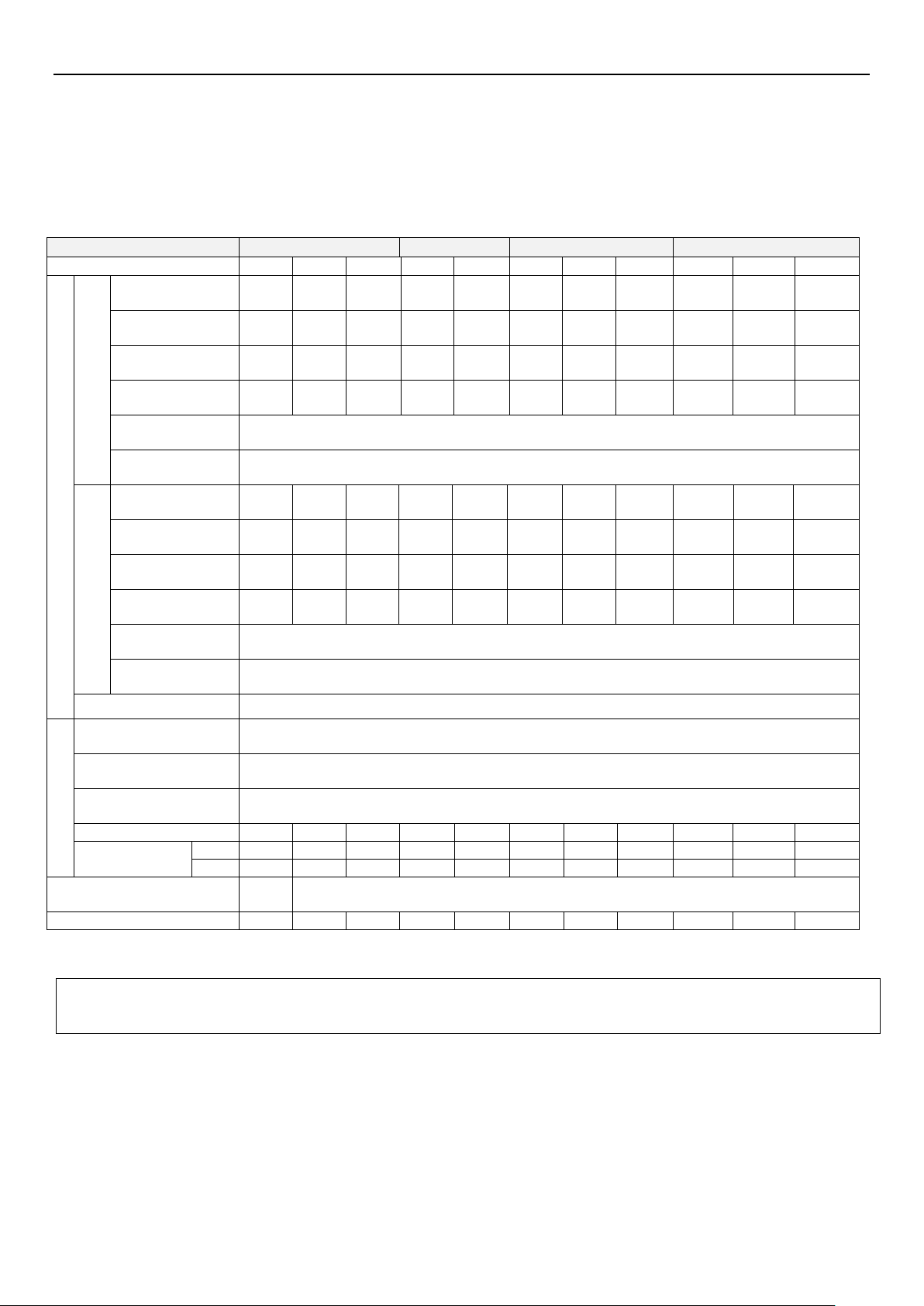
3.1.3 220V series three-phase
Frame
A
B
C
D
Model SE3-023--xy
0.4K
0.75K
1.5K
2.2K
3.7 K
5.5 K
7.5K
11K
15K
Inverter Output
HD
Rated output capacity
(kVA)
1.2
2
3.2
4.2
6.7
9.5
12.5
18.3
24.7
Rated output current (A)
3
5
8
11
17.5
25
33
49
65
Applicable motor
capacity (HP)
0.5
1
2
3
5
7.5
10
15
20
Applicable motor
capacity (kW)
0.4
0.75
1.5
2.2
3.7
5.5
7.5
11
15
Overload current rating
150% 60 seconds, 200% 3 seconds (inverse-time characteristics)
Carrier frequency (kHz)
1~15kHz
N
D
Rated output capacity
(kVA)
1.3
2.1
3.4
4.8
7.4
10.3
13.7
19.4
26.3
Rated output current (A)
3.2
5.5
8.5
12.5
19.5
27
36
51
69
Applicable motor
capacity (HP)
0.5
1
2
3
5
7.5
10
15
20
Applicable motor
capacity (kW)
0.4
0.75
1.5
2.2
3.7
5.5
7.5
11
15
Overload current rating
120% 60 seconds (inverse-time characteristics)
Carrier frequency (kHz)
1~15kHz
Maximum output
voltage
3 phase 200-240V
Power Supply
Rated input AC voltage/
frequency
3 phase 200-240V 50Hz / 60Hz
Permissible AC voltage
fluctuation
3 phase 170-264V 50Hz / 60Hz
Permissible frequency
fluctuation
±5%
Power supply capacity (kVA)
1.5
2.5
4.5
6.4
10
12
17
20
28
Rated input current
(A) *Note 1
HD
3.5
6.0
9.6
13.2
20.4
30
39.6
58.8
78
ND
3.8
6.6
10.2
15
23.4
32.4
43.2
61.2
82.8
Cooling method
Self
cooling
Fan cooling
Weight (kg)
1.0
1.0
1.0
1.5
1.5
4.0
4.1
5.7
5.8
Note 1: The value indicates the current at rated output. The rated input current value is not only affected by power transformer, input side reactor, wiring
condition, but also fluctuates with the impedance of the power supply side.
Note: The test conditions for rated output current, rated output capacity, inverter power consumption are: carrier
frequency (P.72) set default; inverter output voltage 440V; output frequency 60Hz, ambient temperature 40℃.
This manual suits for next models
3
Table of contents
Other Shihlin electric Inverter manuals

Shihlin electric
Shihlin electric SC3-043-7.5K/11KF User manual

Shihlin electric
Shihlin electric SS2-021 Series User manual

Shihlin electric
Shihlin electric SF Series User manual

Shihlin electric
Shihlin electric SL3 Series User manual

Shihlin electric
Shihlin electric SE2 Series User manual

Shihlin electric
Shihlin electric SS2 Series User manual

Shihlin electric
Shihlin electric SC3 Series User manual

Shihlin electric
Shihlin electric SF-GT Series Assembly instructions

Shihlin electric
Shihlin electric SS2 Series User manual


