Kessler-Ellis Products APM-PROC User manual

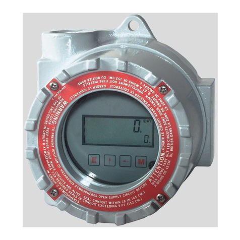
APM-PROC
Process Meter
Quick Start Guide
990374 06/03/16
KESSLER-ELLIS PRODUCTS
10 Industrial Way East
Eatontown, NJ 07724
800-631-2165 • 732-649-7100
Fax: 732-649-7099
http://www.kep.com

Safety Warnings
WARNING: INSTALLATION AND MAINTENANCE MUST BE CARRIED OUT
BY SUITABLY QUALIFIED AND COMPETENT PERSONEL ONLY.
HAZARDOUS VOLTAGES MAY BE PRESENT ON THE CONNECTION
TERMINALS.
INSTALLATION
•Install this product in accordance with local regulations, codes and instructions.
•All fuses must be 0.5A / 250V Type F with a breaking capacity of 35A or greater.
•All conductors carrying hazardous voltage must have external switching or
disconnect mechanisms fitted that provide at least 3 mm of contact separation in all
poles.
•Signal cables connected to this device must not exceed 30 metres long.
•If signal cables are routed outside the building, install extra surge-protection
devices.
Failure to install or operate the unit in accordance with the
above requirements may impair the electrical safety of the unit.
MAINTENANCE
•Before cleaning, inspection or maintenance, isolate all power sources to the unit.
•There are no user-serviceable parts inside this unit. Never open the case.
•Inspect all external wiring connections at regular intervals. Replace any damaged
wiring and tighten any loose connections.
•To clean the unit, use a dry cloth to wipe the casing.
•Take great care connecting the supply. If you connect power to the wrong terminal
s,
it may destroy the unit.

Key Features
Large multi-format display that incorporates:
• 40 segment bar graph display
• Large 4-digit display
• Separate Starburst display area for annuncia-
tors, custom messages and alarm information
• Dynamic backlight color
Programmable:
• Display Range (Both Min & Max Values)
• Custom annunciators
• User-selectable backlight color and intensity
• Two independent alarm set-points
• Two independent outputs
• 4-20mA analogue monitor output
INPUT VOLTAGE CURRENT
Range (DC) 0 to +/-10VDC 0 - 50mA
Impedance 100KΩ 15Ω
Accuracy 0.1% 0.01%
ENVIRONMENTAL
Temperature - operating -10°C to +60°C (14°F to 140°F)
Temperature - storage -40°C to +70°C (-40°F to 158°F)
IP rating (from the front) IP65 / NEMA4
POWER SUPPLY
Nominal Input (AC or DC) 12-24 VAC/VDC
DISPLAY
Number of digits 4
Digit height 12mm [0.47”]
Number of message characters 4
Backlight colours Red, Green, White
LCD display Positive or Negative
OUTPUTS
Max voltage 24V
Max current 50mA
Analogue output 4-20mA
CERTIFICATION UL and cUL (Pending), CE
Visibility:
• User-adjustable backlight brightness and color
• Large display
• Wide viewing angle (horizontal and vertical)
• Custom annunciators
How To Order
EXAMPLE: APM-PROC APO
Series:
Process Meter
Display Type:
APO = Positive LCD
ANO = Negative LCD
Accessories:
APM-E200 - Outdoor Enclosure with cutout for 1 APM
022128-01 = USB Cable
Specications

2
Intended Use
IntendedUse:TheAPMhasbeenspecicallydesignedfor
engineers requiring an effective way to monitor and display
data. The APM accepts a range of electrical inputs (depend-
ing on the model) and displays the data on its integrated
multi-format display. The APM has been designed for installa-
tion into electrical cabinets or display panels. Output models
includetwoindependentoutputsthatcanbeconguredby
the user to be either digital set-point outputs or 4-20mA moni-
tor outputs.
Dimensions
Sw
Pos Bar Graph Annunciator
I
te
m
1234 Input Min 1/2 Max
10000 Custom (Defined in Software Application)
21000Voltage 0 50 100 V %
30100 Voltage 0 50 100 V %
41100Voltage -100 0 100 V %
50010Current 0 50 100I %
61010 Current 0 250500 I °F
70110 Current 0 375750 I °F
81110Current 0 5001000 I °F
90001Current 0 7501500 I °F
10 1001Voltage 0 90 180 RPM
11 0101 Voltage 0 90 180 RPM
12 1101Voltage -180 0 180 RPM
13 0011Current 0 50 100 I °C
14 1011Current 0 75 150 I °C
15 0111 Current 0 100200 I °C
16 1111Current 0 250500 I °C
The DIP switches
are on the back of
the unit.
Input Range
0-10Vdc
0-5Vdc
-10 - +10V
4-20mA
4-20mA
4-20mA
4-20mA
0-20mA
0-10Vdc
0-5Vdc
-10 - +10V
4-20mA
4-20mA
4-20mA
4-20mA
Use the DIP switches to set the Process Meter bar graph
range and annunciators to standard values. Use the software
applicationtocongurecustomsettings.Theswitchpositions
are shown in the table where:
0 = OFF and 1 = ON.
VALUE UNIT
INPUT Voltage Current
Range 0 – 10VDC 10 – 50mA
Impedance 100KΩ15Ω
Accuracy
0.1% of input or
5mV whichever
is greater
0.01% of
input or 5uA
whichever is
greater
Max Working
Voltage 11V 1.5V
DIP Switches
57mm (2.24")
53mm (2.09")
72mm (2.84")
53mm (2.09")72mm (2.84")
Panel Cutout: 68 x 68mm (2.68in) +0.7 -0mm
NOTE: 10-50 mA is only available through the setup software

3
Wiring Diagrams
Inputs
CURRENT INPUT
Ground Referenced
DC POWERED (12 to 24V)
VOLTAGE INPUT
Ground Referenced
DC POWERED (12 to 24V)
VOLTAGE or CURRENT INPUTS
Differential Measurement
DC POWERED (12 to 24V)
WITH EXTERNAL RESET
VOLTAGE or CURRENT INPUTS
Differential Measurement
AC POWERED (12 to 24V)
WITH SETPOINT OUTPUT ON SP1
COM
I input
-
+
-+
12-24V DC PSU
RST
SP1
SP2
Measured
Current
0 - 50mA
-
+
12 to 24V DC PSU
Fuse
ON
1
2
3
4
0V
V input
-+
Measured
Voltage
0 - 10V
(Max Voltage 1.5V
Referenced to
COM Terminal)
COM
NC
I input
-
+
-+
12-24V DC PSU
NC
RST
SP1
SP2
Measured
Current
0 - 50mA
-
+
12 to 24V DC PSU
Fuse
ON
1
2
3
4
(Max Voltage 1.5V
Referenced to
COM Terminal)
COM
I input
-
~
+
~
-+
12-24V AC PSU
RST
SP1
SP2
Measured
Current
0 - 50mA
-
~
+
~
12 - 24V AC PSU
Fuse
ON
1
2
3
4
0V
V input
-+
Measured
Voltage
0 - 10V
(Max Voltage 1.5V
Referenced to
COM Terminal)
SETPOINT 1
OUTPUT
COM
-
+
12-24V DC PSU
RST
SP1
SP2
NC
V input
-+
NC
Measured
Voltage
0 - 10VDC
-
+
12 to 24V DC PSU
Fuse
ON
1
2
3
4
Outputs
EN: 4-20 mA analogue output using setpoint 1.
Note: DC PSU ONLY
DE:
FR:
ES:
IT: Uscita analogica
EN: Using a diode-protected relay on setpoint 1.
Note: DC PSU ONLY
DE:
FR:
ES:
IT: Uscita relè...
EN: Analogue Output and relay using both setpoints.
Note: DC PSU ONLY
DE:
FR:
ES:
IT: Uscite analogiche e relè...
EN: Use the Reset input with the peak hold function
DE:
FR:
ES:
IT: Ingresso di reset...
-
+
12 to 24V
DC
PSUFuse
0V
4-20m
A
Output
-
+
12 to 24V
DC
PSUFuse
RELAY
+
-
-
+
12 to 24V
DC
PSUFuse
RELAY
+
-
0V
4-20mA
-
+
12 to 24V
DC
PSUFuse
RELAY
+
-

4
Setup Software
APM Congurator Software
TheTrumeterAPMConguratorsoftwareallowsyouto
programmecustomcongurationsontoyourAPM.Youcan
set the display range, backlight colour, setpoints and many
other features. Just plug into any USB port on your PC, run
thefreelyavailableAPMConguratorapplicationandyou’re
off. No drivers required.
Download the software at:
http://truapm.com/download-software/
Minimum System Requirements
TheAPMConguratorsoftwareinstallsdirectlyontoa
Windows-based PC. It is not intended to install over a network
orrunfromaserver.TheAPMConguratorsoftwareneeds:
• A PC or laptop running Windows XP, Vista, 7 or 8
operating system, 32- or 64-bit
• Microsoft.NETFramework.(Ifyoudon’thavethis,you
can download it from www.microsoft.com/net).
• A spare USB 2.0 port
• An internet connection for initial software installation and
updates.
• A USB cable with Type A to Type B connectors.
Home Page - APM Congurator Software
The Main setup page shows the Input signal and ranges on the left side of the screen. The right side of the screen shows tab
setup information for Alarm 1, Alarm 2, Backlight, Response and Scale. The default tab is Alarm 1.

5
Alarm 1 Setup - APM Congurator Software
ThersttabisusedtosetupvaluesandfunctionsforAlarm1.
Alarm 2 Setup - APM Congurator Software
The second tab is used to setup values and functions for Alarm 2.

6
Alarm Backlight Setup - APM Congurator Software
The third tab is used to setup color and brightness for the Backlight.
Response Setup - APM Congurator Software
The fourth tab is used to setup the Response time for the display digits, bar graph and alarms.

7
Scale Setup - APM Congurator Software
ThefthtabisusedtosetuptheScale.Upto20input/outputpairscanbeentered.
Table of contents
Other Kessler-Ellis Products Measuring Instrument manuals
Popular Measuring Instrument manuals by other brands

Flowmetrics
Flowmetrics 922-MFC Installation and operating instructions

77 ELEKTRONIKA
77 ELEKTRONIKA DocUReader 2 PRO user manual

KTS-Electronic
KTS-Electronic GPA 500 XS manual

TS-market
TS-market Edic-mini Tiny A39 quick start guide

Elcometer
Elcometer 2350 user guide

DH Instruments
DH Instruments MOLBLOC installation instructions