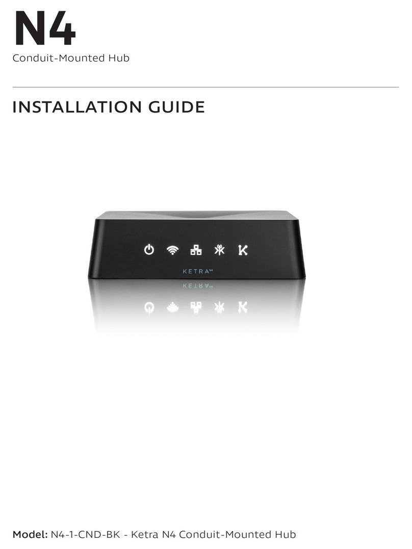
Ketra N4 Series User manual

N4
Conduit-Mounted Hub
Model: N4-1-CND-BK - Ketra N4 Conduit-Mounted Hub
INSTALLATION GUIDE

PAGE 2 770-000027-02 r14 N4 INSTALLATION GUIDE
! !
WARNING
Risk of electric shock. Use in dry locations only.
May result in serious injury or death.
Turn power OFF at circut breaker or remove fuse.
Damage to this product caused by wiring with power on voids the warranty.
Due to the risk of electric shock, a licensed electrician should install this power supply unit in
strict compliance with the National Electric Code and any state or local code which may apply.
This device complies with Part 15 of the FCC Rules. Operation is subject to the following two
conditions: (1) this device may not cause harmful interference, and (2) this device must accept
any interference received, including interference that may cause undesired operation.
Maintain at least 6 feet of spacing between any KetraNet Mesh
product and Wi-Fi routers and access points.
Note: This equipment has been tested and found to comply with the limits for a Class B digital device, pursuant to part 15
of the FCC Rules. These limits are designed to provide reasonable protection against harmful interference in a residential
installation. This equipment generates, uses and can radiate radio frequency energy and, if not installed and used in
accordance with the instructions, may cause harmful interference to radio communications. However, there is no guarantee
that interference will not occur in a particular installation. If this equipment does cause harmful interference to radio or
television reception, which can be determined by turning the equipment o and on, the user is encouraged to try to correct
the interference by one or more of the following measures:
• Reorient or relocate the receiving antenna.
• Increase the separation between the equipment and receiver.
• Connect the equipment into an outlet on a circuit dierent from that to which the receiver is connected.
• Consult the dealer or an experienced radio/TV technician for help.

PAGE 3770-000027-02 r14N4 INSTALLATION GUIDE
Product Overview............................................................................................................................................... page 4
Included Components & Specs....................................................................................................................... page 6
Dimension Drawings.......................................................................................................................................... page 7
Wiring Diagrams................................................................................................................................................. page 8
Pre-Installation.................................................................................................................................................... page 9
Installation............................................................................................................................................................ page 10
Additional Tasks.................................................................................................................................................. page 13
Warranty................................................................................................................................................................ page 14
TABLE OF CONTENTS

PAGE 4 770-000027-02 r14 N4 INSTALLATION GUIDE
PRODUCT OVERVIEW
Ketra’s N4 Hub forms a bridge between Ketra
products and Ketra digital interfaces such as
Design Studio, mobile app, and API commands.
With multiple N4s, a user can integrate KNets, allowing for seamless installations no
matter how large. The Hub can also connect via Internet to Ketra’s cloud servers to
enable backup and remote maintenance functions.
PRODUCT OVERVIEW
Fig. 1
KetraNet Mesh
KetraNet Link
Wi-Fi
Ethernet
Power
Fig. 2
RJ 45 Jacks
Micro USB
Reset Switch

PAGE 5770-000027-02 r14N4 INSTALLATION GUIDE
EXPLANATION OF INDICATOR LIGHTS
The N4 indicates its status using the lights on the front.
INDICATOR LIGHT BEHAVIOR
Symbol Name Expected Behavior
Power • Red briey at startup
• White at all other times while N4 is on
Wi-Fi • For future use
Ethernet
• Red briey at connection to LAN (while N4 waits for an IP address)
• White at all other times while network connection active
• Dark if no LAN connection is detected
KetraNet Mesh
• Blinks red when a “remote access” message is sent or received
• Solid red when the hub is congured for remote access, but the
hub cannot connect to the remote access server
KetraNet Link
• Blinking white when a message is sent or received over KetraNet
Link (wired communication with other Ketra devices)
• Red when no Internet connection is detected
• Dark at all other times
PRODUCT OVERVIEW

PAGE 6 770-000027-02 r14 N4 INSTALLATION GUIDE
INCLUDED COMPONENTS / SPECS
(1) THREADED RING (3) WIRE NUTS
SPECIFICATIONS
(1) N4 CONDUIT-MOUNTED HUB
ENVIRONMENTAL
Operating Temperature -20˚ to 40˚C
Storage Temperature -20˚ to 80˚C
Humidity 0 - 95%, Non-condensing
Certication UL, cUL, FCC Class B, RoHS
Location1UL Damp Location, IP20
MECHANICAL
Weight 15oz, 0.43 kg
Housing Material Polymer
POWER
Voltage 120 VAC
Power Consumption 5W
Current .041 Amps @ 120 VAC
ENCLOSURE + CONNECTIONS
Connections (Class 1)
AC Power In 6 in. 18 AWG Flying Leads
Data Connections
Connectivity Technology Wireless, Wired
Data Link Protocol Ethernet, Fast Ethernet,
IEEE 802.11b, IEEE 802.11g
KetraNet Mesh™ Wireless
USB Port 1 - Micro-B USB console
port, for rmware updates

PAGE 7770-000027-02 r14N4 INSTALLATION GUIDE
DIMENSION DRAWINGS
Fig. 4
Fig. 3

PAGE 8 770-000027-02 r14 N4 INSTALLATION GUIDE
WIRING DIAGRAMS
'
[ESE] [ESE]
KETRA
N4
K
KETRA
N4
BY OTHERS
KETRA
N4
K
KETRA
N4
-
KETRA
N4
KETRA
N4
KETRA
1 OF 1
MODEM/ROUTER
'
[ESE] [ESE]
KETRA
N4
K
KETRA
N4
BY OTHERS
KETRA
N4
K
KETRA
N4
-
KETRA
N4
KETRA
N4
KETRA
1 OF 1
MODEM/ROUTER
Example Installation Layout
KNet: N4 + 49 Ketra Wireless Devices
KEY
KETRANET MESH
WIRELESS NETWORK
KETRA
N4
120-277V
60 Hz
HOT/LINE
NEUTRAL
GROUND
MODEM/ROUTER
CAT5E
(BY OTHERS)

PAGE 9770-000027-02 r14N4 INSTALLATION GUIDE
PRE-INSTALLATION
N4 PLACEMENT
For ideal KetraNet Mesh wireless performance, position the N4 according to these guidelines:
• Keep within range: Place the N4 within 50 feet of at least one of the devices it will control.
Ideally, place as close as possible to all devices it will control.
• Avoid obstructions: Avoid having metal obstructions or walls between the N4 and the
nearest device it will control.
• Avoid metal enclosures.
• Separate from Wi-Fi devices: Maintain at least 6 feet of spacing between any KetraNet Mesh
product and Wi-Fi routers and access points.
The N4 is UL Damp Location-listed.
The N4 has a suggested clearance of 4 inches to ensure visibility of indicator lights and access to all ports. (See g. 5.)
NETWORK CONFIGURATION
The modem or router to which the N4 is connected must include a DHCP server from which the N4 can obtain an IPv4
address. (For the vast majority of modems and routers, this is the default.)
All N4s that will be part of an installation together must be on the same LAN (Local Area Network) subnet.
4”
4”
Fig. 5

PAGE 10 770-000027-02 r14 N4 INSTALLATION GUIDE
INSTALLATION
1. Remove a half-inch knockout from the junction box.
2. Mount the N4 to the junction box. Fit the N4’s connector into the opening created in step 1.
Secure the N4 by threading the provided threaded ring onto the mount.
Notes:
–
Orientation: The N4’s serial number (on the bottom) should face the access point.
The serial number may be necessary for commissioning and servicing.
–
Clearance: Remove nearby obstructions. This will ensure the visibility of the indicator lights
as well as access to all ports.
3. Splice the N4 into building power. Using the provided wire nuts, attach each lead wire to the corresponding
conductor. All connections should be made inside the junction box.
– Black: Line
– White: Neutral
– Green: Ground
4. Energize the circuit.
Note: Once power is connected, the N4’s power indicator light will come on. It will be red while the
N4 boots up; afterward, it will turn white.
STEP 1
APPLY POWER TO THE HUB
INSTALLATION

PAGE 11770-000027-02 r14N4 INSTALLATION GUIDE
STEP 2
CONNECT THE HUB TO THE LAN (LOCAL AREA NETWORK)
There are two methods of doing this, shown below. Choose the one that best ts the needs of the installation. Once a
connection is detected, the N4s Ethernet indicator, , will come on white.
OPTION 1: DIRECT CONNECTION TO MODEM OR ROUTER.
• Use a CAT5 or equivalent Ethernet cable
• Cable can be no more than 100 m (328 ft)
Fig. 6
N4
Modem/
Router
Use either RJ45 port
CAT5 or equivalent
Ethernet cable
INSTALLATION

PAGE 12 770-000027-02 r14 N4 INSTALLATION GUIDE
OPTION 2: CONNECTION TO A CHAIN OF N4S.
• Use either RJ45 port for input/output
• Maximum of 10 N4s per chain
• Use a CAT5 or equivalent Ethernet cable
• Cable can be no more than 100 m (328 ft)
Warning: If any N4 in the chain is powered o, all N4s further down will be unable to connect to the LAN.
CAT5 or equivalent
Ethernet cable
Fig. 7
Use either RJ45 port
KNet
N4 + 49 Ketra
Wireless Devices
KNet KNet KNet
Cables no more than
100 m (328 ft) Modem/Router
INSTALLATION

PAGE 13770-000027-02 r14N4 INSTALLATION GUIDE
CONTROLLING WITH DESIGN STUDIO:
For simple instructions on establishing an N4 installation in Design Studio, refer to the N4 edition of our Design Studio
Quick Start Guide.
For more advanced instructions on establishing an N4 installation in Design Studio, refer to the following portions
of the Design Studio User Manual:
•
Getting Started
>
Installation Management
>
Creating an Installation
•
Operating an Installation
>
Organization
If you are unable to discover your N4s in Design Studio, conrm one of the following is true:
OPTION 1:
– Your computer is on the same subnet as all N4s
OR
OPTION 2:
– Your computer is on the same network as the N4s
– All N4s are on the same subnet
– The N4s have internet access
– Your computer has internet access
CONTROLLING WITH THE KETRA MOBILE APP:
For instructions on using an N4 with the Ketra app, refer to our Mobile App Manual.
If you are unable to discover your N4s in the Ketra app, conrm one of the following is true:
OPTION 1:
– Your mobile device is on the same subnet as all N4s
OR
OPTION 2:
– Your mobile device is on the same network as the N4s
– All N4s are on the same subnet
– The N4s have internet access
– Your mobile device has internet access
ADDITIONAL TASKS

PAGE 14 770-000027-02 r14 N4 INSTALLATION GUIDE
Limited warranty terms can be found at:
www.ketra.com/warranty
For questions and technical support please contact:
(512) 872-4349
support@ketra.com
WARRANTY & TECH SUPPORT

6321 E. Stassney Ln.
Suite 400
Austin, TX 78744
ketra.com
(512) 347-1100
Other manuals for N4 Series
3
This manual suits for next models
1
Table of contents
Other Ketra Switch manuals