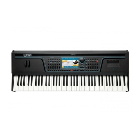
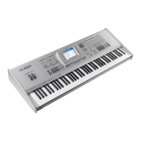
KETRON Audya 8 User manual

ESPANSIONE RAM
Audya Series
I_AUDYA_SERIE_28_04_2011.indd 1 28/04/2011 11:00:06
ISTRUZIONI PER IL MONTAGGIO
DELL'ESPANSIONE RAM
INSTRUCTIONS TO INSTALL THE
RAM EXPANSION
ANLEITUNG ZUR INSTALLATION
DER RAM SPEICHERWEITERUNG
INSTRUCTIONS POUR LE MONTAGE
DE LA CARTE MEMOIRE

IMPORTANTI NORME DI SICUREZZA
I_AUDYA_SERIE_28_04_2011.indd 2 28/04/2011 11:00:10

Pagina 3
1
2
4
3
2
2
8
4
5
KETRON - MDKT46AS - 25/02/2009
Fig. 1
AUDYA

1
2
3
4
5
SVITARE LE 3 VITI POSTE
SUL FONDO
SVITARE LE 2 VITI POSTE
SULLE FIANCATE LATERALI
SVITARE LE 7 VITI POSTE
SUL LATO POSTERIORE
ALZARE DI ALCUNI CENTIMETRI
IL COPERCHIO COMANDI
VERSO L' ALTO FACENDO
ATTENZIONE A NON
DANNEGGIARE
I CABLAGGI
RUOTARE IL COPERCHIO COMANDI
ED APPOGGIARLO SU UN PIANO
20
29
29
20
Pagina 3
AUDYA5
3
2
2
7
FIG. 2

1
3
4
5
6
KETRON - MDKT60AS - 20/06/2011
ISTRUZIONI APERTURA STRUMENTO
2
SVITARE LE 9 VITI POSTE
SUL FONDO
SVITARE LE 2 VITI POSTE
SULLE FIANCATE LATERALI
SVITARE LE 7 VITI POSTE
SUL LATO POSTERIORE
ALZARE DI ALCUNI CENTIMETRI
IL COPERCHIO COMANDI
VERSO L' ALTO FACENDO
ATTENZIONE A NON
DANNEGGIARE
I CABLAGGI
RUOTARE IL COPERCHIO
COMANDI ED
APPOGGIARLO SU
UN PIANO
RUOTARE LA CALOTTA
TASTIERA
AUDYA8
Fig. 3

1
2
3
4
KETRON - MDKT61AS
OPEN INSTRUMENT INSTRUCTIONS
5
5
Page 3
AUDYA4
5
5
FIG. 4

ISTRUZIONI PER L’APERTURA DI AUDYA (FIG. 1)
1. Svitare le 4 viti poste sul fondo
2. Svitare le 2 viti poste sulle fiancate laterali
3. Svitare le 8 viti poste sul lato posteriore
4. Alzare di alcuni centimetri il coperchio comandi verso l’alto facendo attenzione a
non danneggiare i cablaggi
5. Ruotare il coperchio comandi ed appoggiarlo su un piano
OPEN AUDYA INSTRUCTIONS (FIG. 1)
1. Remove all (4) screws placed on bottom
2. Remove (2) screws located on side panels
3. Remove (8) screws located on back panel
4. Lift up (for some inch) top panel and move it carefully to avoid unintentional unplug
cable
5. Rotate top panel even to lean working area
ANLEITUNG ZUM ÖFFNEN DES AUDYA GEHÄUSES (FIG. 1)
1. Entfernen Sie alle (4) Schrauben am Gehäuseboden
2. Entfernen Sie (2) die Schrauben an den Seitenteilen
3. Entfernen Sie (8) die Schrauben am Rück-Panel
4. Heben Sie das Gehäuseoberteil (einige Zentimeter) an und klappen Sie es
vorsichtig auf, um mögliches Trennen der Steckverbindungen zu vermeiden
5. Legen Sie das Gehäuseoberteil wie abgebildet ab.
INSTRUCTIONS POUR L’OVERURE DE L’AUDYA (FIG. 1)
1. Enlever toutes les vis (4) situées sur le fond
2. Enlever toutes des vis (2) situées sur les côtés
3. Enlever toutes des vis (8) situées à l'arrière
4. Afin d’éviter des déconnections involontaires, soulevez délicatement la face
supérieure de quelques centimètres
5. Faire pivoter la face avant et la poser délicatement à plat sur le plan de travail
ISTRUZIONI PER L’APERTURA DI AUDYA5 (FIG. 2)
1. Svitare le 3 viti poste sul fondo
2. Svitare le 2 viti poste sulle fiancate laterali
3. Svitare le 7 viti poste sul lato posteriore
4. Alzare di alcuni centimetri il coperchio comandi verso l’alto facendo attenzione a
non danneggiare i cablaggi
5. Ruotare il coperchio comandi ed appoggiarlo su un piano
OPEN AUDYA5 INSTRUCTIONS (FIG. 2)
1. Remove all (3) screws placed on bottom
2. Remove (2) screws located on side panels
3. Remove (7) screws located on back panel
4. Lift up (for some inch) top panel and move it carefully to avoid unintentional unplug
cable
5. Rotate top panel even to lean working area

ANLEITUNG ZUM ÖFFNEN DES AUDYA 5 GEHÄUSES (FIG. 2)
1. Entfernen Sie alle (3) Schrauben am Gehäuseboden
2. Entfernen Sie (2) die Schrauben an den Seitenteilen
3. Entfernen Sie (7) die Schrauben am Rück-Panel
4. Heben Sie das Gehäuseoberteil (einige Zentimeter) an und klappen Sie es
vorsichtig auf, um mögliches Trennen der Steckverbindungen zu vermeiden
5. Legen Sie das Gehäuseoberteil wie abgebildet ab.
INSTRUCTIONS POUR L’OVERURE DE L’AUDYA5 (FIG. 2)
1. Enlever toutes les vis (3) situées sur le fond
2. Enlever toutes des vis (2) situées sur les côtés
3. Enlever toutes des vis (7) situées à l'arrière
4. Afin d’éviter des déconnections involontaires, soulevez délicatement la face
supérieure de quelques centimètres
5. Faire pivoter la face avant et la poser délicatement à plat sur le plan de travail
ISTRUZIONI PER L’APERTURA DI AUDYA8 (FIG. 3)
1. Svitare le 9 viti poste sul fondo
2. Ruotare la calotta tastiera
3. Svitare le 2 viti poste sulle fiancate laterali
4. Svitare le 7 viti poste sul lato posteriore
5. Alzare di alcuni centimetri il coperchio comandi verso l’alto facendo attenzione a
non danneggiare i cablaggi
6. Ruotare il coperchio comandi ed appoggiarlo su un piano
OPEN AUDYA8 INSTRUCTIONS (FIG. 3)
1. Remove all (3) screws placed on bottom
2. Turn the keyboard block
3. Remove (2) screws located on side panels
4. Remove (7) screws located on back panel
5. Lift up (for some inch) top panel and move it carefully to avoid unintentional unplug
cable
6. Rotate top panel even to lean working area
ANLEITUNG ZUM ÖFFNEN DES AUDYA 8 GEHÄUSES (FIG. 3)
1. Entfernen Sie alle (3) Schrauben am Gehäuseboden
2. Drehen die den Tastaturblock
3. Entfernen Sie (2) die Schrauben an den Seitenteilen
4. Entfernen Sie (7) die Schrauben am Rück-Panel
5. Heben Sie das Gehäuseoberteil (einige Zentimeter) an und klappen Sie es
vorsichtig auf, um mögliches Trennen der Steckverbindungen zu vermeiden
6. Legen Sie das Gehäuseoberteil wie abgebildet ab.

INSTRUCTIONS POUR L’OVERURE DE L’AUDYA8 (FIG. 3)
1. Enlever toutes les vis (9) situées sur le fond
2. Tourner l’enveloppe de le clavier
3. Enlever toutes des vis (2) situées sur les côtés
4. Enlever toutes des vis (7) situées à l'arrière
5. Afin d’éviter des déconnections involontaires, soulevez délicatement la face
supérieure de quelques centimètres
6. Faire pivoter la face avant et la poser délicatement à plat sur le plan de travail
ISTRUZIONI PER L’APERTURA DI AUDYA4 (FIG. 4)
1. Svitare le 5 viti poste sul fondo
2. Svitare le 5 viti poste sul lato posteriore
3. Alzare di alcuni centimetri il coperchio comandi verso l’alto facendo attenzione a
non danneggiare i cablaggi
4. Ruotare il coperchio comandi ed appoggiarlo su un piano
OPEN AUDYA4 INSTRUCTIONS (FIG. 4)
1. Remove all (5) screws placed on bottom
2. Remove all (5) screws located on back panel
3. Lift up (for some inch) top panel and move it carefully to avoid unintentional unplug
cable
4. Rotate top panel even to lean working area
ANLEITUNG ZUM ÖFFNEN DES AUDYA 4 GEHÄUSES (FIG. 4)
1. Entfernen Sie alle (5) Schrauben am Gehäuseboden
2. Entfernen Sie (5) die Schrauben am Rück-Panel
3. Heben Sie das Gehäuseoberteil (einige Zentimeter) an und klappen Sie es
vorsichtig auf, um mögliches Trennen der Steckverbindungen zu vermeiden
4. Legen Sie das Gehäuseoberteil wie abgebildet ab.
INSTRUCTIONS POUR L’OVERURE DE L’AUDYA 4 (FIG. 4)
6. Enlever toutes les vis (5) situées sur le fond
7. Enlever toutes des vis situées (5) à l'arrière
8. Afin d’éviter des déconnections involontaires, soulevez délicatement la face
supérieure de quelques centimètres
9. Faire pivoter la face avant et la poser délicatement à plat sur le plan de travail

Accessori per fissaggio scheda di espansione: N. 2 viti, N. 4 distanziatori, N. 2 dadi
Accessories for mounting the expansion card: N. 2 screws, N. 4 standoff, N. 2 nuts
Zubehör für die Montage der Speichererweiterung: 2x Schrauben, 4x Distanzringe, 2x
Muttern
Les accessoires de montage de la carte d'extension : 2 vis plastiques, 4 entretoises
plastiques et 2 écrous plastiques
Togliere le 5 viti e relative rondelle indicate dalle frecce
Remove all 5 screws and washers indicated by the arrows
Entfernen Sie die markierten 5 Schrauben und Beilagscheiben
Enlever les 5 vis et leurs rondelles, indiquées par les fleches

Sollevare la scheda e inserire le 2 viti negli appositi fori indicate
Lift the card and insert the 2 screws in the holes indicated
Heben Sie die Platine an und setzen Sie die 2 Schrauben in die markierten Bohrungen wie
abgebildet
Soulever légèrement la carte et insérer les 2 vis dans les trous indiqués
Inserire 2 distanziatori su ogni vite
Insert 2 standoff on each screw
Setzen Sie 2 Distanzringe auf jede Schraube
Insérer 2 entretoises sur chaque vis

Inserire l'espansione di memoria negli appositi connettori e viti
Insert the memory expansion in the proper connectors and screws
Setzen Sie die Speichererweiterung ein wie abgebildet
Insérer la carte mémoire dans les connecteurs appropriés et les vis
Fissare l'espansione di memoria con i 2 dadi
Secure memory expansion with the 2 nuts
Schrauben Sie die Speichererweiterung mit den 2 Muttern fest
Fixer la carte mémoire avec les deux écrous

Fissare la scheda con le 5 viti precedentemente tolte
Secure the card with all 5 screws removed previously
Fixieren Sie die Platine wieder mit den zuvor gelösten 5 Beilagschreiben und Schrauben
Remettre en place les 5 vis enlevées précédemment
Switch (SW2) da settare per il funzionamento dell'espansione di memoria
Switch (SW2) to be set to use the expansion memory
Bringen Sie die Schalter (SW2) in die Stellung für Verwendung mit der
Speichererweiterung
L’utilisation de la carte mémoire optionnelle nécessite le paramétrage du circuit Minidip
(SW2)

Settaggio switch senza espansione di memoria
Setting switches without expansion memory
Schalterstellung OHNE Speicherweiterung
Réglage du Minidip sans carte mémoire
Settaggio switch con espansione di memoria
Setting switches with memory expansion
Schalterstellung MIT Speichererweiterung
Réglage du Minidip avec carte mémoire

VEGA 119
Notes

KETRON s.r.l.
Via Giuseppe Taliercio n. 7
60131 Ancona (Italy)
Tel. +39 071 285771
Tel. +39 071 2857748
www.ketron.it
email: [email protected]
Stampato in Italia
I_AUDYA_SERIE_28_04_2011.indd 204 28/04/2011 11:01:37
This manual suits for next models
2
Other KETRON Synthesizer manuals

KETRON
KETRON AUDYA 4 User manual

KETRON
KETRON X1 Wiring diagram

KETRON
KETRON AUDYA Series User manual

KETRON
KETRON AUDYA Series User manual

KETRON
KETRON SD9 PRO live station User manual

KETRON
KETRON SD90 PRO live module User manual

KETRON
KETRON SD1 User manual

KETRON
KETRON SD9 User manual

KETRON
KETRON SD7 User manual