Key Digital KD-C5CWP User manual

521 East 3rd Street, Mount Vernon, NY 10553
Phone :: 914.667.9700 Fax :: 914.668.8666
Web :: www.keydigital.com
Rev 0 – March 2007
The BobCAT Series™devices will convert analog video and analog or digital audio sources for
transmission over CAT5 and CAT6 wire. The BobCAT Series™devices will act as a transmitting
or receiving unit.
Please read all warnings and CAT5 distance limitations inside the manual.
KD-CAT5XRCA(1
*
) KD-CAT5XBNCKD-C5CWP
Operating Manual
Component Video and Digital Audio Balun
Key Digital
®
, led by digital video pioneer Mike Tsinberg,
develops and manufactures high quality, cutting-edge
technology solutions for virtually all applications where
high quality video imaging is important. Key Digital
®
is at the forefront of the video industry for Home
Theater Retailers, Custom Installers, System Integrators,
Broadcasters, Manufacturers, and Consumers. We
provide
total video system solutions because we know
and help drive the technology, the industry, the business,
and all the latest up-and-coming standards. But most
of all, we know exactly what you need for your unique
application - the right solution.
*Model number KD-CAT5XRCA1 contains additional cable accessories for connection to a source unit and/or display.

Page 4
Page 1
Quick Set Up Guide
Y (green cable)
Pr (red cable)
Pb (blue cable)
PCM/CV (digital audio/
coaxial audio)
Y (green cable)
Pr (red cable)
Pb (blue cable)
PCM/CV (digital audio/
coaxial audio)
(Please adjust DIP switch
Settings, found on page 9)
Up to 700 ft.
(Please see Distance
limitations Found on
page 8)
Analog BobCAT Series
™
KD-CAT5XRCA /
KD-CAT5XBNC /
KD-C5CWP
Analog BobCAT Series
™
KD-CAT5XRCA /
KD-CAT5XBNC /
KD-C5CWP
CAT5/6 Cable
Please read all instructions to insure safe operation of the product.
Table of Contents
Dolby
®
7.1 Audio Application Example..................................2
Installation Instructions.............................................3
RGBHV Video plus L/R Audio Application Example .......................4
Additional Installation Tips ..........................................5
Component (YPrRb) Video with 5-Channel Surround Application Example......6
RJ45 (CAT5) Cable Pinout . . . . . . . . . . . . . . . . . . . . . . . . . . . . . . . . . . . . . . . . . .8
Cable Distance and Supporting Resolution .............................8
Dispwitch Settings................................................9
Troubleshooting ..................................................9
Technical Specifications...........................................10
Safety instructions ...............................................11
Product Warnings ...............................................12
Warranty ......................................................12
How to Contact Key Digital
®
........................................13
© 2007 Key Digital, Inc. All rights reserved.

Page 2
Page 3
Installation Instructions
1. Find a safe and convenient location for your Analog BobCAT unit.
Before permanently securing the unit or final installation of cabling behind
walls or ceilings, test for proper operation of the unit and the cables in your
system.
2. Connect your Component Video sources to the Component Video ports of
the BobCAT intended as the transmitting device.
Please note that each Analog BobCAT can be used as either the transmitting or
receiving device. Therefore, it makes no difference in the order in which they are
connected. Additionally, any BobCAT unit (whether RCA, BNC connector or Wall
Plate version) is interchangeable and can be used with any other BobCAT version.
3. Connect your Coaxial Digital Audio source to the PCM port of the BobCAT
intended as the transmitting device.
The BobCAT supports any PCM signal, including standard Left/Right digital audio
and Dolby Digital
®
encoded bit streams. If you are not running audio with video
through the BobCAT, simply leave this port disconnected.
4. Connect one end of your CAT 5 cable to the CAT 5 port of the BobCAT
intended as the transmitting device and the other end of your CAT 5 cable to
the CAT 5 port of the BobCAT intended as the receiving device.
Use standard CAT 5 cable for interconnectivity between each set of BobCAT
devices.
5. Connect the Component Video ports of the BobCAT intended as the
receiving device to the Component inputs of your receiving device (display,
switcher, etc…).
6. Connect the PCM port of the BobCAT intended as the receiving device to
the Coaxial Digital Audio inputs of your receiving device (display, A/V receiver,
etc…).
Again, if you are not running audio with video through the BobCAT, simply leave
this port disconnected.
➔
➔
➔
➔
➔
Dolby®7.1 Audio Application Example (Four Box Setup)
L
C
R
LS
RS
L side
R side
Sub
Box 1 Tx Box 1 Rx
Box 2 Tx Box 2 Rx
CAT5/6 Cable
CAT5/6 Cable
L
C
R
LS
RS
L side
R side
Sub

Page 4
Page 5
Additional Installation Tips
The BobCAT is incredibly flexible in its possible uses. In addition to the standard setup
as a Component Video and PCM Digital Audio extender, the unit can also be used for
other signals. The following signals are all supported on any BobCAT port, regardless of
the silk screened labels on the case.
Analog Audio Signals (line level)
H and V Sync Signals
Composite Video Signals
Any YPbPr Signal (whatever the sync configuration may be)
RGB with Composite Sync (four coaxial line)
With the above information in mind, you can see how the additional setup options below
make the BobCAT a powerful and useful tool in any installation*.
Example One – Four BobCAT Setup to support RGBHV with L/R Analog Audio
In this case, we can use two BobCAT units to transmit RGBHV signals in addition to left
and right line level analog audio signals over two CAT 5 cables. To do so:
Connect RGB cables to corresponding ports labeled “R, G, and B” on the first
transmitting BobCAT.
Connect H sync cable to the port labeled “PCM” on the first transmitting BobCAT.
Connect V Sync cable to the port labeled “PCM” on
the second transmitting BobCAT.
Connect left analog audio signal to the port labeled “R” on
the second transmitting BobCAT.
Connect right analog audio signal to the port labeled “G” on
the second transmitting BobCAT.
Use two additional BobCAT units to receive the two CAT 5 cables from the transmitting
units above. Take care to connect output cables (RGBHV and L/R audio) to the ports
that correspond to those used for input on the transmitting BobCAT.
➔
➔
➔
➔
➔
1.
2.
3.
4.
5.
ANY input on BobCAT can be used for any of the following video/ audio signals as
long as you use the same output on the termination unit. Y,Pr,Pb,R,G,B,H,V, S-Video,
Composite Video (CV), Left Front Audio, Right Front Audio, Center Speaker, Subwoofer,
Left Rear Audio, Right Rear audio (Any Audio configurations from 2.0 – 7.1 and beyond).
In some cases this requires a “multi-box” application.
RGBHV Plus L/R Audio Application Example (Four Box Setup)
G
R
B
H
CAT5/6 Cable
R
V
L
CAT5/6 Cable
Box 1 Tx Box 1 Rx
Box 2 Tx Box 2 Rx
G
R
B
H
R
V
L

Page 6
Page 7
Additional Installation Tips
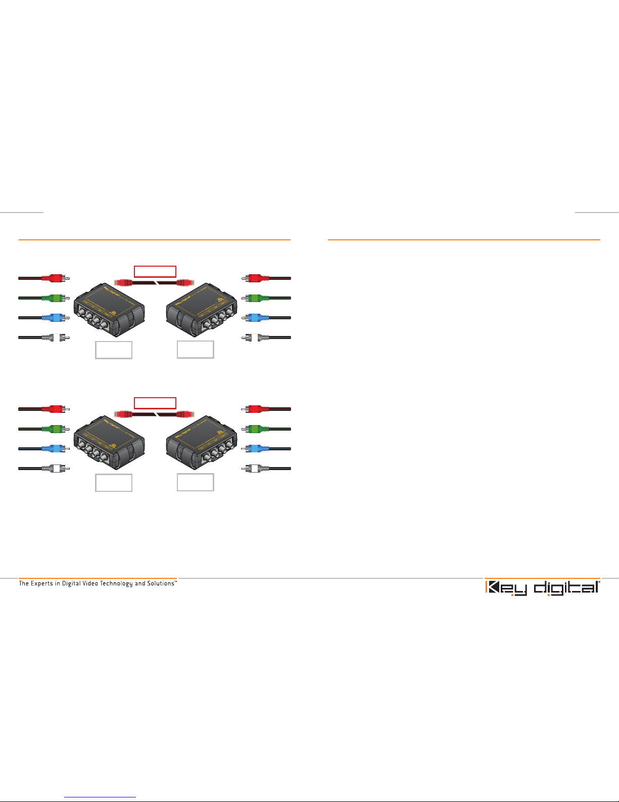
Example Two – Four BobCAT Setup to support RGB with Multi-Channel Analog
Audio
In this case, we can use two BobCAT units to transmit Component Video (RGB) signals
in addition to multi-channel (L, C, R, LS, RS) analog audio.
To do so:
Connect Component Video cables to the corresponding ports labeled “R,G, and B”
on the first transmitting BobCAT.
Connect left analog audio signal to the port labeled “PCM” on the first transmitting
BobCAT.
Connect the center, right, LS, and RS analog audio signals to the ports labeled
“R, G, B, and PCM”, respectively, on the second transmitting BobCAT.
Use two additional BobCAT units to receive the two CAT 5 cables from the transmitting
units above. Take care to connect output cables (RGB and L, C, R, LS, and RS) to the
ports that correspond to those used for input on the transmitting BobCAT.
1.
2.
3.
*Note that these are just two examples of the many different possible configurations.
If you keep in mind that inputs and outputs should be one-to-one (that is, the signal
feeding a specified port on the transmitting BobCAT can be output on the corresponding
port on the receiving BobCAT) then there are many uses for multiple BobCAT setups with
the formats mentioned above.
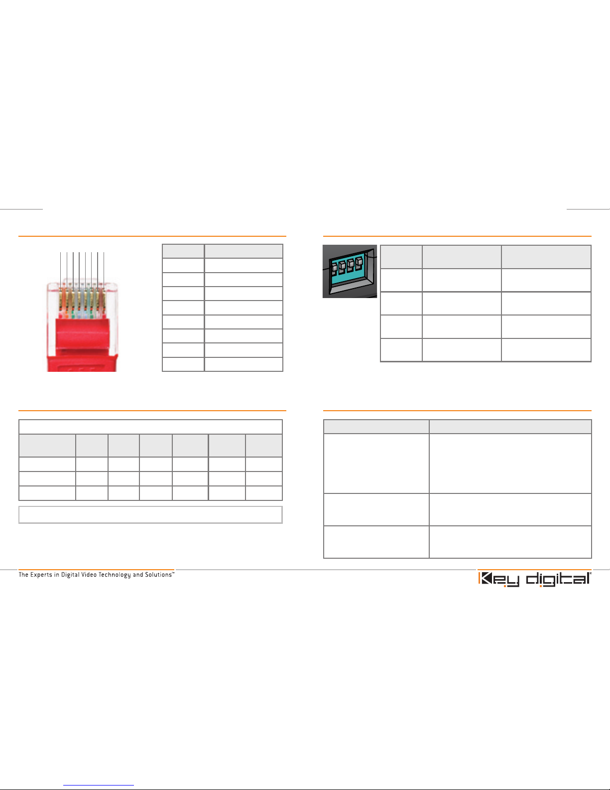
Additionally, the BobCAT units DIP switches connect shield to common ground when set
to “On”. Switch “1” is for “R” port, switch “2” is for “G” port, switch “3” is for “B” port, and
switch “4” is for “PCM” port. Connecting shield to common ground can help eliminate
visible “noise” on the video signal. See “Troubleshooting” section of this manual.
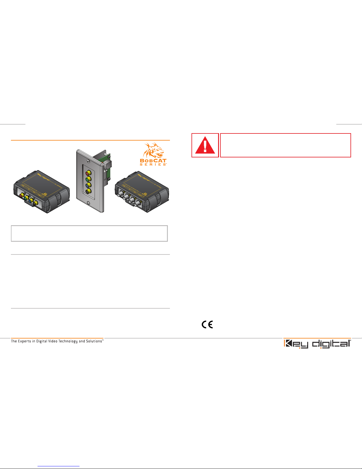
Component (YPrPb) Video with 5-Channel Surround Application Example
(Four Box Setup)
ANY input on BobCAT can be used for any of the following video/ audio signals.
As long as you use the same output on the termination unit. Y,Pr,Pb,R,G,B,H,V, S-Video
(with break-out cable), Composite Video (CV), Left Front Audio, Right Front Audio, Center
Speaker, Subwoofer, Left Rear Audio, Right Rear audio (Any Audio configurations from 2.0
– 7.1 and beyond). In some cases this requires a “multi-box” application.
Y
Pr
Pb
L
C
R
LS
RS
Box 1 Tx Box 1 Rx
Box 2 Tx Box 2 Rx
CAT5/6 Cable
CAT5/6 Cable
C
R
LS
RS
Y
Pr
Pb
L

Page 8
Page 9
DIP Switch Settings
DIP
switch
ON OFF
1
PCM/CV connected to
common ground
PCM/CV is not connected
to common ground
2
Pb connected to
common ground
Pb is not connected to
common ground
3
Yconnected to
common ground
Yis not connected to
common ground
4
Pr connected to
common ground
Pr is not connected to
common ground
RJ45 (CAT5) Cable Pinout
1 2 3 4 5 6 7 8
RJ45 Pin Wire Color
1
White/Green
2
Green
3
White/Orange
4
Blue
5
White/Blue
6
Orange
7
White/Brown
8
Brown
Cable Distance and Supporting Resolution
Component Video: ■Composite Video: ▲PCM Digital Audio: ●
CAT5 Cable
Length
480i 480p 576i 576p 720p 1080i
300’
■ ▲ ●■ ●■ ▲ ●■ ●■ ●■ ●
500’
■ ▲ ●■ ●■ ▲ ●■ ● ● ●
700’
■ ▲ ■ ▲
Troubleshooting
Problem Solution
Display has visible lines and/or
colors appear incorrectly.
A device or cable in the system may not be
properly grounded. Replace Component cables.
Also, set DIP switch settings on the BobCAT
individually to on/off positions.
These switches connect (on) / disconnect (off)
cabling to common ground.
Display drops in/out in intervals. Cable length may be too long for desired
resolution. Shorten CAT 5 cable length or lower
the resolution you are using.
Audio drops in/out in intervals PCM digital audio signals should run reliably up to
500 feet. If audio drops out at lengths above this,
try a shorter CAT 5 cable length.
Note: Performance for Shielded (STP) and Unshielded (UTP) cables is identical.

Page 10
Page 11
Technical Specifications
BobCAT Series
™
Connectors
One set of Component Video ports (In or Out) labeled “R, G, B” with the following
connectors:
YPbPr coaxial analog video connectors.
One PCM Digital Audio port (In or Out) labled “PCM”:
Coaxial PCM audio connector on black female RCA jack.
One CAT5 port (In or Out) labled “CAT 5”:
Standard CAT 5 RJ45 jack.
Mechanical
No fan noise
Product Weight: < 1 lb
Enclosure type: Molded ABS Plastic
›
➔
›
➔
›
➔
›
›
›
Read these instructions.
Keep these instructions.
Heed all warnings.
Follow all instructions.
Do not use this apparatus near water.
Clean only with dry cloth.
Do not block any ventilation openings. Install in accordance with the
manufacturer’s instructions.
Do not install near any heat sources such as radiators, heat registers, stoves, or
other apparatus (including amplifiers) that produce heat.
Only use attachments/accessories specified by the manufacturer.
Refer all servicing to qualified service personnel. Servicing is required when the
apparatus has been damaged in any way, such as power-supply cord or plug is
damaged, liquid has been spilled or objects have fallen into the apparatus, the
apparatus has been exposed to rain or moisture, does not operate normally, or
has been dropped.
1.
2.
3.
4.
5.
6.
7.
8.
9.
10.
Safety Instructions.
Please be sure to follow these instructions for safe
operation of your unit.
KD-CAT5XBNCKD-C5CWP
KD-CAT5XRCA(1
*
)
*Model number KD-CAT5XRCA1 contains additional cable accessories for connection to
a source unit and/or display.

Page 12
Page 13
Always test all connections, especially self-made CAT5 cable and Component
cables coming into the device.
Please set all DIP switch configurations appropriately. DIP switches connect shield
to common ground when set to “On”. Switch “1” is for “R” port, switch “2” is for “G”
port, switch “3” is for “B” port, and switch “4” is for “PCM” port. Connecting shield
to common ground can help eliminate visible “noise” on the video signal. See
“Troubleshooting” section of this manual.
If installing the analog bobcat into wall or mounting bracket into sheet-rock,
provide proper screw support with bolts or sheet-rock anchors.
Quality of CAT5 cable.
CAT5 “crimping” or creating the connection yourself must be done as thoroughly
as possible or picture quality and/or cable distance will suffer.
Do not pull hard or force CAT5 cable, there is a high chance it may break.
Warranty
All Key Digital
®
products are built to high manufacturing standards and should provide
years of trouble-free operation. They are backed by a limited two-year parts and labor
warranty.
1.
2.
3.
1.
2.
3.
Important Product Warnings:
Distances for CAT5 are suggestive
and depend on the following factors:
How to Contact Key Digital®
Repairs and Warranty Service
Should your product require warranty service, please contact Key Digital
®
to obtain a
Returned Materials Authorization (RMA) number
Please contact us at either:
Phone: 1-914-667-9700 ext 215
E-mail: rma@keydigital.com
Technical Support
For technical questions about using our products, please contact us at either:
Phone: 1-914-667-9700 ext 216
Phone: 1-914-667-9700 ext 301
E-mail: tech@keydigital.com
Customer Support
For customer support questions about using our products, please contact us at
either:
Phone: 1-914-667-9700 ext 223
E-mail: customersuppor[email protected]
Feedback
Please e-mail any comments/questions about the manual to:
E-mail: customersuppor[email protected]
›
›
➔
➔
›
➔
➔
➔
›
➔
➔
›
➔
Other manuals for KD-C5CWP
2
This manual suits for next models
3
Table of contents
Other Key Digital Media Converter manuals

Key Digital
Key Digital KD-CAT5XCAT5 User manual

Key Digital
Key Digital KD-VCS500 User manual

Key Digital
Key Digital KD-AAXDA User manual

Key Digital
Key Digital KD-IP922ENC User manual

Key Digital
Key Digital KD-IP922ENC User manual

Key Digital
Key Digital KD-CAT5XRCA User manual

Key Digital
Key Digital KD-C5CWP User manual

Key Digital
Key Digital KD-FIX418A User manual

Key Digital
Key Digital HD Leeza KD-HD1080P User manual

Key Digital
Key Digital KD-CAT5XST User manual