Key Digital KDVW4X4PRO4K User manual

Key Digital
®
, led by digital video pioneer Mike Tsinberg,
develops and manufactures high quality, cutting-edge
technology solutions for virtually all applications where
high-end video and control are important. Key Digital
®
is at the forefront of the video industry for Home Theater
Retailers, Custom Installers, System Integrators,
Broadcasters, Manufacturers, and Consumers.
4 Inputs to 4 Outputs
Video Wall Processor,
supports Seamless Matrix Switching
The Experts in Digital Video Technology and Solutions™
KD-VW4x4Pro
Operating Instructions
Rev 0 – Apr 2016
Key Digital®Systems :: 521 East 3rd Street :: Mount Vernon, NY 10553
Phone : 914.667.9700 Fax : 914.668.8666 Web : www.keydigital.com
KD-VW4x4Pro_Manual.indd 2-3 4/25/16 4:39 PM

4 1
Table of Contents
About KD-VW4x4Pro......................................................... 1
Quick Setup Guide .......................................................... 2
Application Example ......................................................... 3
Connections, Buttons and LEDs ................................................ 4
IR Remote Control........................................................... 8
Video Wall Modes .......................................................... 10
RS-232 & TCP/IP Commands ................................................. 18
Bezel Control for Video Wall Mode.............................................. 21
Specifications ............................................................. 23
Important Product Warnings & Safety Instructions: ................................. 24
How to Contact Key Digital ................................................... 25
Warranty Information ........................................................ 25
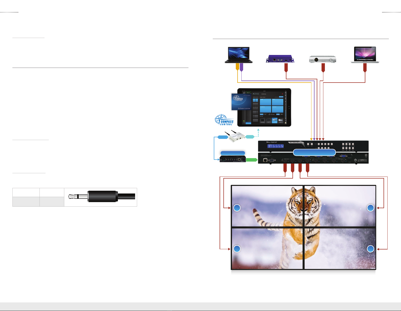
About KD-VW4x4Pro
Key Digital’s Video Wall Series, KD-VW4x4Pro, enables you to turn standard consumer or
professional displays into a video wall. This video wall processor features eight different video wall
modes including many horizontal and vertical layouts in addition to 2x2. KD-VW4x4Pro supports
seamless 4x4 matrix switching, and analog to digital conversion of incoming VGA with analog
audio signals.
KD-VW4x4Pro is designed to fit a wide variety of professional video installation and live-event
needs. It is ideal for retail digital signage, conference & board room, bar/restaurant, house of
worship, corporate A/V, data monitoring centers, and more.
Key Features
›HDMI Matrix Switching:
4 HDMI/Analog sources to 4 HDMI outputs, independent when in
matrix mode
›Seamless Switching:
Un-interrupted screen transitions during source selections
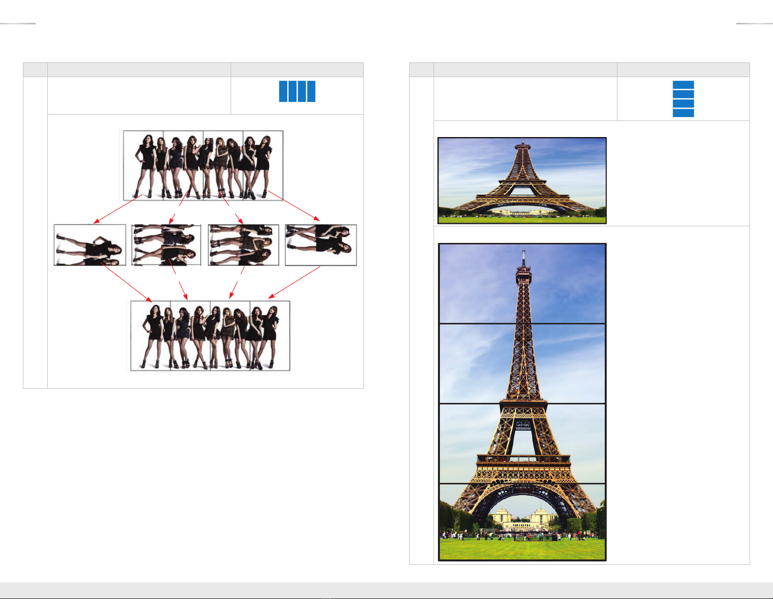
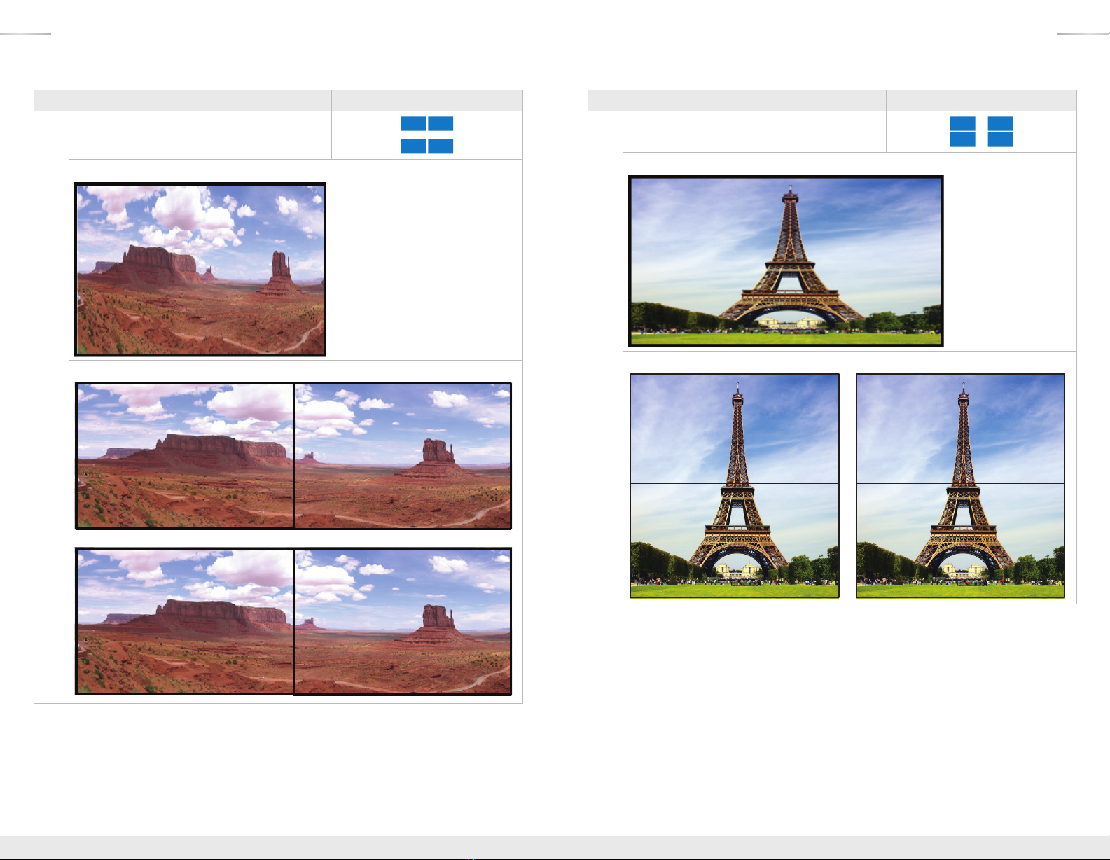
›Video Wall Processing:
Transform consumer and professional displays into a video wall with
eight video wall modes
»Horizontal (4): 1x4 Rotated, 1x4, 1x3, and two sets of 1x2
»Vertical (3): 4x1, 3x1, and two sets of 2x1
»2x2
›Bezel Control:
Create a fluid screen transition by removing pixels from top, bottom, left, and
right border independently
›EDID:
Internal library with 5 default EDID configurations for each input, in addition to native EDID
data for any Output/Display
›Full Buffer™Technology
: Full buffering of HDCP and EDID, for the fastest possible switching
and viewing of any source/input to any display/output, regardless of multiple output viewing
relation
›TMDS re-clocking
: Support for long HDBaseT/CAT5e/6 or HDMI connections
and many layers of connectivity.
›Deep Color Support:
Up to 12 bits/color
›Control:
Front panel buttons, Serial IR, Optical IR, RS-232, and TCP-IP, including video wall
mode select, matrix switching, EDID Control and discrete on and off via IR
›Control System Support: Compatible with Compass Control
®
, AMX
®
, Control4
®
, Crestron
®
,
KNX
®
, RTI
®
, Savant, URC
®
, Leviton
®
, etc.
Accessories
›Power supply: KD-PS12V3ASC, 12V/3A, Screw-in type
›IR Remote control: KD-RMVW4x4
›Rack Ears
© 2016 Key Digital, Inc. All rights reserved.
Always follow the instructions provided in this Operating Manual.
Please check the Key Digital Website for the most up-to-date Manual.
KD-VW4x4Pro_Manual.indd 4-1 4/25/16 4:39 PM

2 3
Rack Mounting:
›Secure the rack ears to each side of the
KD-VW4x4Pro
with the supplied hardware, then fasten
the unit to the rack rails with the included machine screws.
Quick Setup Guide
1. Begin with the KD-VW4x4Pro and all input/output devices turned off and power
cables removed.
2. Connect HDMI and/or Analog Video and Audio Sources to the desired KD-VW4x4Pro
input ports.
3. Connect display devices to the HDMI outputs.
4. Connect power to the KD-VW4x4Pro and power on, then repeat for source devices, then
display devices.
5. Choose desired mode via front panel buttons, IR, RS-232 or TCP-IP.
»a. Please refer to following sections for more information on controllability and setup for
each control type.
IR Emitter Control
When using an IR Emitter / IR Extender (sold separately), the IR Emitter must be mounted over
the IR Sensor on the front of the KD-VW4x4Pro. One end of the cable is connected to the IR
Receiver/ Master Controller / IR Extender / IR Connecting Block, while the other end is mounted
over the IR Sensor of the KD-VW4x4Pro
Serial IR Control
As a more robust alternative to optical IR, KD-VW4x4Pro may also be controlled via hard-wired IR.
Use a 3.5mm Male Mono plug with the IR Signal carried on the tip of the connector.
Tip Ring
TX or RX None
Application Example
Digital
Signage
HDMI Laptop
Cable/Satellite
Video Wall Modes
iPad
VGA
L/R
KD-VW4x4Pro
1 2
3 4
HDMI
HDMI
HDMI
KD-MC1000
Master Controller
RS-232
VGA Laptop
HDMI
HDMI
HDMI
HDMI
Router
RJ45 WiFi
KD-VW4x4Pro_Manual.indd 2-3 4/25/16 4:39 PM

4 5
Connections, Buttons and LEDs
Rear Panel Connections:
All connections to the KD-VW4x4Pro are found on the rear panel of the unit. Refer to the
illustrations below for port assignments while making connections.
HDMI InputsHDMI Outputs Serial IRTCP/IP RS-232 Power
VGA/DB15 & Analog L/R Inputs
Input Connections
Located on the right side (HDMI) and top center (VGA/Analog L/R) of the back panel
›HDMI Inputs (4 Total)
»Compatible with HDMI 1.4a and HDCP 1.x standards
»Active link (voltage + data) with connected source indicated by illuminated LED
»Does not support CEC
»Does not support incoming audio formats greater than 2-channel.
»The connection is automatically muted if the selected audio source format is not
2-channel PCM.
Audio Format from Input Source Coaxial Digital Audio Output
2CH PCM Pass-through
Multi-Channel PCM MUTE
DOLBY/DTS MUTE
HD Audio MUTE
›VGA / DB15 Inputs (4 total)
»VGA / DB15 supported input resolutions:
»640x480@60/75, 800x600@56/60/75, 1024x768@60/75, 1280x768@60/75,
1366x768@60/75, 1280x1024@60/75, 1440x900@60/75, 1600x900@60,
1600x1200@60, 1920x1080@60, 1920x1200@60
›Analog L/R Inputs (4 total)
»3.5mm stereo connector
»Associated with VGA input only
»Sampling frequency = 48KHz, 24Bits
»2 VRMS Line Audio L/R input signal
Output Connections
Located on the right side of the back panel.
›HDMI Outputs (4 Total)
»Compatible with HDMI 1.3b standard
»Output resolution is fixed to 1080p@60 fps
»Supports 2-channel audio only
»Does not support DVI video format / connections
»Active link (voltage + data) with connected output indicated by illuminated LED
Control & Power Ports
Located on the left-most (RS-232, and TCP-IP) and right-most (power and serial IR) sides of the
back panel.
›The RS-232 port is used for control, as well as firmware updates
»Refer to RS-232 Commands and Protocol section for complete code-set
›
Pin 5 – Ground
Pin 3 – Receive
Pin 2 – Transmit
RS-232 cable pin out
The RS-232 baud rate is 57,600
›The RS-232 port is a Female connection,
and is straight-thru
»Pin 2 = Tx
»Pin 3 = Rx
»Pin 5 = Ground
›The TCP-IP port is used for control, as well as firmware updates
»Refer to RS-232 and TCP-IP Commands and Protocol section for complete code-set
›The Serial IR port is a 3.5mm Mono connector for hard-wired IR signals
»Tip = IR Signal
»Ring = Ground
›The Power port is a screw-type connection.
»Thread power connection to KD-VW4x4pro unit before connecting to power outlet
KD-VW4x4Pro_Manual.indd 4-5 4/25/16 4:39 PM

6 7
Front Panel Operation
Video Wall Mode
HDMI/VGA Select
Matrix Mode Switching
The front-panel of KD-VW4x4Pro features 3 sets of buttons:
›HDMI / VGA input-type select (2 buttons)
»Enables selection of the HDMI digital video input or VGA analog video input for the specified
source
»
To select HDMI or VGA input type:
»1. Press the desired Input 1, 2 , 3, or 4 (video source)
»2. Press either HDMI or VGA, as desired, to lock in the setting
»3. Confirmation example: V is for VGA, H would be present for HDMI
›Matrix Mode Switching select (2 rows of 4 buttons, plus All button)
»Enables selection of any input source (1-4) for the selected output, or to select a single
source to be viewed on all outputs
»
To configure matrix switching:
»1. Choose the desired output you would like to control, or All,
using the Output 1, 2, 3, 4, or All buttons
»2. Choose the desired Input 1, 2 , 3, or 4 (video source) you would like to view
on the selected output (or all outputs)
»3. Confirmation example:
»When in matrix mode, the chosen output and the current source is indicated by a blue fill of
the respective Output and Input buttons
»If a Video Wall Mode is chosen, the Input being viewed by the outputs is illuminated
»Matrix Output Select buttons are not illuminated when in video wall mode
›Video Wall Mode Select: (2 rows of four buttons)
»Enables the selected source to be displayed across all outputs in the desired layout
»
To select video wall mode:
»1. Choose the desired video wall layout
»2. Choose the desired Input 1, 2 , 3, or 4 (video source) you would like to
view for that layout
»3. Confirmation example::
»When 1Vx3H and 3Vx1H video wall modes have been selected,
video muting is applied to output 4
»When 1Vx2H and 2Vx1H modes have been selected, there are two sets available:
Outputs 1 + 2, and Outputs 3 + 4
›Factory Default Reset via the Front panel
»To reset the unit to Factory Default settings, simultaneously press and hold the HDMI Input-
Type Select button and Video Wall Mode 1 (2Vx2H) button for approximately 10 seconds
»Default Settings:
»Unit Address is 00
»Unit is set to Matrix mode
»Output 1 is set to Input 1, 2 with 2, 3 with 3, 4 with 4
»EDID to all inputs is Default 2 (1080p, 2ch audio)
»All other internal parameters set to default
KD-VW4x4Pro_Manual.indd 6-7 4/25/16 4:39 PM

8 9
A
B
C
IR Remote Control
The IR Remote Control included with KD-VW4x4Pro provides
convenient, but limited control of the switching features and
unit setup.
In addition to discrete power on, power off buttons and
function buttons R1, R2, and R3, there are 3 main groups of
controls:
»A.
Output Selection or Video Wall Selection
»B.
Input Selection or Source Type
»C.
Device Select buttons.
›The remote is powered by a CR2025 type battery
›The circular IR sensor accepts control signals from the
remote control.
The sensor is located on the center of the front panel.
Matrix Switching via IR
To execute a matrix switching command, press the desired
Output number, or “ALL” (A) and then the desired Input
number (B).
›A» B
Video Wall Modes via IR
To execute a video wall command, follow these three steps, press the VW button (A), press the
Device Select numerical button (C) for the desired video wall mode, and then select an Input
button (B) to apply the mode.
›VW » C » B
Below is the table of Video Wall modes for Device Select button.
Device Select
Button #
Video Wall Mode View
12 Vertical x 2 Horizontal
21 Vertical x 4 Horizontal,
Rotated Displays CCW
34 Vertical x 1 Horizontal
41 Vertical x 4 Horizontal
51 Vertical x 3 Horizontal
63 Vertical x 1 Horizontal
71 Vertical x 2 Horizontal, Mirrored
82 Vertical x 1 Horizontal, Mirrored
More information can be found on the Video Wall Modes section for a more in-depth description of
the modes.
EDID Control via IR
KD-VW4x4Pro has a built-in library of 5 EDID settings and the ability to copy EDID data from any
output specified via IR, RS-232, and TCP-IP. EDID Control setup via RS-232 and TCP-IP can be
found in the RS-232 Commands and Protocol TCP-IP Setup and Control sections.
›Set to Default EDID
»To change the EDID settings for a particular input via IR, press the following buttons on the
IR remote control: R2
»
R1
»
R3
»
B
»
C
»B= Desired Input to provide EDID. Chose from Input buttons 1-4 (B)
»C= Desired Default EDID. Chose a number from below to the corresponding Device
Select buttons (C)
EDID # Default EDID Description
11080i, 2CH AUDIO
21080p, 2CH AUDIO (Unit default)
31280x720 DVI
41280x1024 DVI
51920x1080 DVI
Copy EDID from Output
»To copy EDID from an Output to an Input, press the following buttons on the remote control:
R2
»
R1
»
R3
»
B
»
A
»B= Desired Input to provide EDID. Chose from Input buttons 1-4 (B)
»A= Desired Output to copy EDID from. Chose from Output buttons 1-4 (A)
EDID Control
EDID authentication is provided from the KD-VW4x4Pro unit to the connected input / source
device. The EDID file (AKA “handshake”) is selected by using the IR remote or RS232/TCP-IP
commands. This file provides a list of compatible video and audio formats as well as digital data,
informing the source device what it should output. Most sources will comply with a new EDID file
without a power-cycle, but each source may behave differently.
KD-VW4x4Pro_Manual.indd 8-9 4/25/16 4:39 PM

10 11
Addressing via IR
The KD-VW4x4Pro may be addressed to avoid controlling multiple units with one IR remote. Once
applied, all IR remote controls must precede with a two digit number before sending the IR remote
control. The default address is 00.
›Set a two-digit address to your KD-VW4x4Pro unit
»Press the following buttons on the remote control: R3 » R1 » R2 » C
1
» C
2
»C
1
= Number value 0 to 9 from the Device Select Number Pad (C)
»C
2
= Number value 0 to 9 from the Device Select Number Pad (C)
›Example: If you want to set the system address to 05, using the IR remote, the sequence must
be: R3 » R1 » R2 » 0 (Device Select) » 5 (Device Select)
If a unit address other than 00 is applied, all commands via IR will require an address prefix. The
address prefix is entered using the Device Select buttons.
›Example: If system address is 02 and you want to set all outputs to input 1, using the IR remote,
the sequence must be:
0 (Device Select) » 2 (Device Select) » ALL (Output Selection) » 1 (Input Selection)
RS-232 and TCP-IP codes also require an address prefix if an address other than 00 is applied.
More information is available in the RS-232 and TCP-IP Commands and Protocol section.
Video Wall Modes
KD-VW4x4Pro supports 8 video wall modes:
# Video Wall Mode Configuration
12 Vertical x 2 Horizontal
21 Vertical x 4 Horizontal, Rotated Displays CCW
34 Vertical x 1 Horizontal
41 Vertical x 4 Horizontal
51 Vertical x 3 Horizontal
63 Vertical x 1 Horizontal
71 Vertical x 2 Horizontal, Mirrored
82 Vertical x 1 Horizontal, Mirrored
Important Note about Source Content:
It is necessary to obtain/create content that maintains the aspect ratio of the video wall mode.
»A common display’s aspect ratio is 16:9.
»Example: Working in the 4V x 1H mode, the width is 1 to 1 (1:1), but the height is 1 to 4
(1:4) because of the 4 vertical displays.
»Therefore, the correct source content should be 16:36
»Tip: 16 times 1 equals 16 for the width. 4 times 9 equals 36 for the height.
# Video Wall Mode 1 Configuration
12 Vertical x 2 Horizontal
›Ideal aspect ratio of source content, 16:9
12
34
KD-VW4x4Pro_Manual.indd 10-11 4/25/16 4:39 PM

12 13
# Video Wall Mode 2 Configuration
21 vertical x 4 horizontal with displays rotated 90
degrees counter clock-wise
›Ideal aspect ratio of source content, 36:16
Original Image from Input Source
Scale & rotate 90 degree to clock wise
Rotate & Arrange Display
1x4 Video Wall Display
1234
123 4
1
2
3
4
# Video Wall Mode 3 Configuration
34 Vertical x 1 Horizontal
›Ideal aspect ratio of source content, 16:36
Original Source:
4V x 1H Video Wall Output:
1
2
3
4
KD-VW4x4Pro_Manual.indd 12-13 4/25/16 4:39 PM

14 15
# Video Wall Mode 4 Configuration
41 Vertical x 4 Horizontal
›Ideal aspect ratio of source content, 64:9
Original Source:
1V x 4H Video Wall Output:
1
23 4
# Video Wall Mode 5 Configuration
51 Vertical x 3 Horizontal
›Ideal aspect ratio of source content, 48:9
Original Source:
1V x 3H Video Wall Output:
123
# Video Wall Mode 6 Configuration
61 Vertical x 2 Horizontal, Mirrored
›Ideal aspect ratio of source content, 16:27
Original Source:
3V x 1H Video Wall Output:
1
2
3
KD-VW4x4Pro_Manual.indd 14-15 4/25/16 4:39 PM

16 17
# Video Wall Mode 7 Configuration
71 Vertical x 2 Horizontal, Mirrored
›Ideal aspect ratio of source content, 32:9
Original Source:
1V x 2H Video Wall Output:
12
34
# Video Wall Mode 8 Configuration
82 Vertical x 1 Horizontal, Mirrored
›Ideal aspect ratio of source content, 16:18
Original Source:
2V x 1H Video Wall Output:
1
2
3
4
KD-VW4x4Pro_Manual.indd 16-17 4/25/16 4:39 PM

18 19
RS-232 & TCP/IP Commands
The KD-VW4x4Pro provides access to all functions when used with an RS-232 or TC/IP control
system or computer.
The connection protocol is as follows:
»Baud rate: 57,600
»Data Bits: 8
»Parity: None
»Stop Bits: 1
»Flow Control: None
»Carriage Return: Required
»Line Feed: Required
Pin 5 – Ground
Pin 3 – Receive
Pin 2 – Transmit
RS-232 cable pin out
NOTE: Commands are not case sensitive. Spaces are shown for clarity; commands should not
have any spaces. Every command below requires a carriage return at the end of the string for the
command to be executed. If a new command is received, a prompt should be sent back.
TCP/IP Setup:
›The default TCP-IP address is 192.198.0.200
»You can connect to the unit on a 192.168.0.xxx type router, or using a crossover cable
directly from your computer
»If you are not using a 192.168.0.xxx type network, you can adjust the TCP-IP address and
port number settings via RS-232 to your desired network setup, and then connect to the
unit.
›The default TCP-IP port number is 23
›Control commands are exactly the same via TCP-IP as they are via RS-232
Response from Help command
(list and description of all available RS-232 / TCP-IP commands):
Example: h\r Response from Status command
(current settings and/or status of unit):
Example: sta\r
KD-VW4x4Pro_Manual.indd 18-19 4/25/16 4:39 PM

20 21
Bezel Control for Video Wall Mode
Window Border
The area on the outer edge of each display may be pinched to make the images blend together
through the display’s bezel. These commands may be used to adjust these bezels.
»For Left Border: SPO xx VCL yy
»For Right Border: SPO xx VCR yy
»For Top Border: SPO xx VCT yy
»For Bottom Border: SPO xx VCB yy
»xx = Selected Output (01-04), yy = pixel value for border (00-99)
Example: How to pinch the horizontal and vertical space on a 2x2 video wall by adding 20 pixels.
»
Display 1 Right Border needs to move right
»SPO 01 VCR 20
»Display 1 Bottom Border needs to move down
»SPO 01 VCB 20
»Display 2 Left Border needs to move left
»SPO 02 VCL 20
»Display 2 Bottom Border needs to move down
»SPO 02 VCB 20
»Display 3 Right Border needs to move right
»SPO 03 VCR 20
»Display 3 Top Border needs to move up
»SPO 03 VCT 20
»Display 4 Left Border needs to move left
»SPO 04 VCL 20
»Display 4 Top Border needs to move up
»SPO 04 VCT 20
Tip: These borders can be adjusted in any way. For an all-in-one solution for
control and setup, pair the KD-VW4x4Pro with Compass Control
®
for the
greatest ease in configuring you video wall.
KD-VW4x4Pro_Manual.indd 20-21 4/25/16 4:39 PM

22 23
There are 4 kinds of borders for each display:
For a more natural look, adjust these borders to blend in the picture
Specifications
Technical:
›Input (Each): 1 HDMI connector, Type A, 19 pin female; 1 HD analog video 15-pin female,
1 analog audio connector, 3.5mm stereo female
›Output (Each): 1 HDMI connector, Type A, 19 pin female
›Bandwidth: TMDS bandwidth 4.95 Gb/s
›Link: Single Link
›DDC Signal (Data): Input DDC Signal - 5 Volts p-p (TTL)
›HDMI Video/Audio Signal: Input Video Signal - 1.2 Volts p-p
›DDC Communication: EDID and HDCP Bi-directional Transparency from Display to Source ›
Wired IR: Modulated IR signal input, 0-5V TTL or -10 to +10V, 3.5mm mono female connector
with signal on tip
›Power: External Power supply, 12V 3A
General:
›Regulation: CE, RoHS, WEEE
›Rack Mount:
1U, Full Rack Width (rack ears included)
›Enclosure: Black Metal
›Product Dimensions:
17.25” x 7.1” x 1.75”
›Shipping Dimensions:
22.8” x 8.5” x 3.2”
›Product Weight:
6.5 lb.
›Shipping Weight:
8 lb.
KD-VW4x4Pro_Manual.indd 22-23 4/25/16 4:39 PM

24 25
Important Product Warnings:
1. Connect all cables before providing power to the unit.
2. Test for proper operation before securing unit behind walls or in hard to access spaces.
3. If installing the unit into wall or mounting bracket into sheet-rock, provide proper screw support
with bolts or sheet-rock anchors.
Safety Instructions:
Please be sure to follow these instructions for safe operation of your unit.
1. Read and follow all instructions.
2. Heed all warnings.
3. Do not use this device near water.
4. Clean only with dry cloth.
5. Install in accordance with the manufacturer’s instructions.
6. Do not install near any heat sources such as radiators, heat registers, stoves, or other
apparatus (including amplifiers) that produce heat.
7. Only use attachments/accessories specified by the manufacturer.
8. Refer all servicing to qualified service personnel. Servicing is required when the device has
been damaged in any way including:
»Damage to the power supply or power plug
»Exposure to rain or moisture
Power Supply Use:
You MUST use the Power Supply provided with your unit or you VOID the
Key Digital®Warranty and risk damage to your unit and associated equipment.
How to Contact Key Digital
®
System Design Group (SDG)
For system design questions please contact us at:
›Phone: 914-667-9700
›E-mail: [email protected]
Customer Support
For customer support questions please contact us at:
›Phone: 914-667-9700
›E-mail: [email protected]
Technical Support
For technical questions about using Key Digital
®
products, please contact us at:
›Phone: 914-667-9700
›E-mail: [email protected]
Repairs and Warranty Service
Should your product require warranty service or repair, please obtain a
Key Digital
®
Return Material Authorization (RMA) number by contacting us at:
›Phone: 914-667-9700
›E-mail: [email protected]
Feedback
Please email any comments/questions about the manual to:
›E-mail: [email protected]
Warranty Information
All Key Digital
®
products are built to high manufacturing standards and should provide years of
trouble-free operation. They are backed by a Key Digital Limited 3Year Product Warranty Policy.
http://www.keydigital.com/warranty.htm
KD-VW4x4Pro_Manual.indd 24-25 4/25/16 4:39 PM
This manual suits for next models
1
Table of contents
Other Key Digital Media Converter manuals

Key Digital
Key Digital HD Leeza KD-HD1080P User manual

Key Digital
Key Digital KD-AAXDA User manual

Key Digital
Key Digital KD-CAT5XRCA User manual

Key Digital
Key Digital KD-FIX418A User manual

Key Digital
Key Digital KD-C5CWP User manual

Key Digital
Key Digital KD-C5CWP User manual

Key Digital
Key Digital KD-C5CWP User manual

Key Digital
Key Digital KD-IP922ENC User manual

Key Digital
Key Digital KD-IP922ENC User manual

Key Digital
Key Digital KD-CAT5XCAT5 User manual