Paradox IPC10 User manual

1
BETA VERSION
For latest manual updates, please refer to paradox.com/Manuals/IPC10.pdf.
The following manual describes the basic connections and programming required to get your Paradox IPC10 Converter up and running.
Introduction
The IPC10 receives signals from Paradox systems/accounts encoded with Paradox IP protocol, records them, converts them to known formats,
and sends them to central monitoring station (CMS) software. The IPC10 is basedon MQTT technology that is continuously supervised, reliable,
and fast.Reporting from the Panel to the CMS, the cycleis usually less than 100ms. Created for the modern CMS with a low footprint and
minimal wire connections, it offers a high account capacity of up to 5,000, onecable connection,very low power consumption, reliability,and
redundancy.
Main Features:
•Up to 5,000 supervised accounts (20, 10, or 5 minutes supervision) and 3,500 accounts at 90 seconds.
•100ms reporting cycle from panel to CMS.
•Fully encrypted communications with ALS 128-bit certificates.
•Fully supervised
•Simple and fast up time with minimal programming for input (reporting devices) and output ports to CMS, with no registration from
reporting devices is required.
•One single-wire Ethernet connection, for data and POE; no other connections are needed.
•Support all legacy Paradox systems with IP180 or upgraded IP150+ or PCS265V7.
•5 minutes up and running replacement, new receiver same as replaced receiver, only IP address and port configuration needed (can be
prepared before, and normal operation for all accounts will be restored in full.
•Connect to CMS software via local Ethernet, supports Sur-Guard MLR2-DG or Ademco 685 formats.
•10,000 event internal buffer in case of lost CMS.
•Simple and minimal UI
•Low footprint (rack mount 1U) and low power consumption
•CMS receives offline and online restore status without the need for a new event from the panel.
•Fully remotely upgradable via local Ethernet.
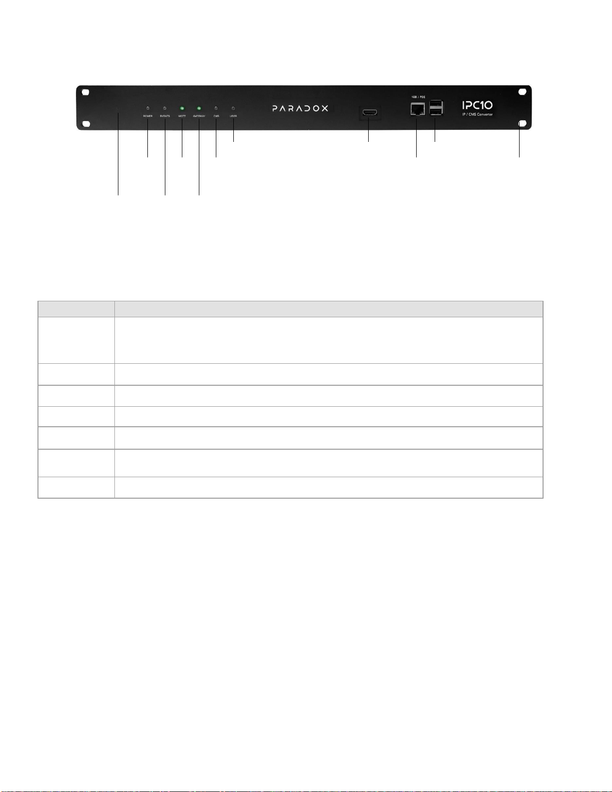
Figure 1

2
IPC10 Overview
Figure 2
LED Indicators
LED
Description
Reset
Use pin to press the reset button. Momentary press will restart the converter.
Note: All stored evets will be erased upon reboot.
Reset to default - Press for at least 10 seconds and depress. LEDs will shut down and the IPC10 will restart; all values
will be set to default and all data (including events) will be deleted.
Power
Green –Power ON
Events
Green blinking –Data transmission from reporting devices
MQTT
Green –MQTT active
Gateway
Green - Valid gateway
CMS
Green –Connected to the CMS
Amber blinking –Transmitting data to the CMS
User
Green –User connected to the IPC10 web page
Location and Mounting
The IPC10 can be mounted on a 19” (48.3 cm) rack.
Hardware Installation
Connect the Ethernet cable from the router with POE to the Ethernet port located in the front of the IPC10 Converter, refer to Figure 2.
Note!: It is strongly recommended to have the POE router connected to a professional UPS to avoid loss monitoring in case of power failure.
MQTT
LED
User
LED
CMS
LED
N/A
N/A
Power
LED
Ethernet
Port
Mounting
Holes
Reset
Switch
Events
LED
Gateway
LED

3
Configuration
1. Search over the local network for the IP address of the IPC10 you are looking for using a standard IP scanner. It will appear as IPC10-
SERIALNUMBER. The serial number will be printed also on the label of the IPC10 in the back.
2. Enter the IPC10 IP address you found with the scanner in a web browser, followed by port 8080 to access the web user interface of the
IPC10(e.g.,http://192.168.1.110:8080). The USER led on the receiver will light up, and you will access the UI of the IPC10.
3. Enter the IPC10 name. This will be used to identify the converter physically on the rack in case you have more the one converter on the
network. We suggest printing the name and sticking it on the front face of the receiver.
4. Enter password of minimum 6 alphanumeric or symbols (case sensitive). Confirm password. Keep the password in safe place as If you
lose the password, you must reset the receiver and reprogram it, however all logs and events will be lost. Use pin to press the reset
button on front of IPC-10 as in Fig-2. When multiple IPC10 are installed, you can also locate it with the user LED which will be on when
logged in.
The IPC10 web page provides access to the following five menu options:
Events
Allows you to view account and converter related events, can be useful if CMS is down.
Up to
5,000 events will be buffered based on first-in, first-out basis.
Accounts
Allows you to view all system accounts.
SecurityProfiles
Allows you to view security profiles available for the reporting devices.
Configuration
Allows you to configure the converter to operate (IP, port, time, etc...)
About
Allows you to view the IPC10 system information and upgrade the module.
5. Select the Configuration tab to program the converter at the central station, refer to the table below.

4
DHCP
DHCP is selected by default. IP address will be assigned by the router. STATIC IP ADDRESS must be
programmed at the CMS router by the IT manager based on the MAC address of the IPC10 that can
be found in the about page.
UI Web Port
Default is set to 8080 and can be changed if needed. Defines the port number
assigned for Web User
Interface access. Port numbers can be between 1 to 65535.
IP Address
Defines the local converter network address set up by the CMS IT manager. The IP address programmed at
the reporting device’s end, is forwarded internally at the CMS to the local IP address of the receiver. The
remaining fields should be
assigned by the DHCP (network, gateway, DNS primary and secondary) or
programmed manually if the DHCP is off.
Netmask
To be assigned by the CMS IT manager or by the DHCP service.
Gateway
To be assigned by the CMS IT manager or by the DHCP service.
DNS Primary
To be assigned by the CMS IT manager or by the DHCP service.
DNS Secondary
To be assigned by the CMS IT manager or by the DHCP service.
Reporting Devices Port
Default MQTT access is 8883.
6. Configure CMS output fields:
Output Protocol: Default set to Sur-guard MLR2-DG
CMS Port: Enter CMS port.
Enter Receiver and Group ID.
CMS Output Configuration
Output
Allows you to configure the output protocol used by the IPC10 Converter to the CMS
software. Sur-Gard
MLR2-DG (default) and Ademco 685 are supported.
IP
Defines the IP address assigned to the CMS.
Port
Defines the port number assigned. Port numbers can be between 1 to 65535.
Receiver ID
Defines the unique ID assigned to the IPC10. The Receiver ID can be between 01
and 99 Sur-Gard
MLR2 and 1 to 9 for Ademco 685.
Group ID
Allows to assign the converter to a group ID in the central station setup. Can be between 001 to 999
Sur-Gard MLR2 and 1 to 9 for Ademco 685.
Group ID Length
Allows you to change the Group ID length from 1, 2, or 3-digits based on the CMS needs. Example: If CMS
needs 3-digits, enter 3- digits, 001, 00F, etc.
Wait ACK
Defines the amount of time that the IPC10 Converter will wait for an
acknowledgment from the monitoring
station’s automation software before sending a
message.
Link Test
Defines the interval at which the link test is performed with the CMS software.
Test Network
Allows you to test the communication between the IPC10 receiver and the CMS software. Once the test is
complete, a Testing CMS Network window will be displayed indicating the results of the test.
TwoStageAuthentication
Defines if two stage authentication is Enabled or Disabled.
CMS Tag
Default is set to 0.
AdditionalField
Additional information can be added to the event transmitted to the CMS like panel
SN, device SN or
MAC address (default is set to none).

5
Other Configuration
NTP
Allows you to configure the NTP server to use for the IPC10 date and time.
Alternate NTP
Allows you to configure an alternative NTP as a backup of the primary NTP server to
use for the IPC10
date and time.
Time Zone
Select the appropriate time zone to match the location installation.
Converter Events
The following converter account events report the status of the converter. They are configurable and are added to the code list in the CMS
software.
Generate Logs button
Is used to generate logs for R&D analysis and diagnosis. It will generate a file
called IPC10mainlogs(ser#)(Date).zip that is saved on the PC in the downloads
Restore to Factory Default button
This will reset all settings to factory default, including list of events.
Pressing this button and confirming with receiver master code will reset receiver to
factory default, all data will be erased, and receiver has to be reconfigured. This
can be performed also by pressing with a pin on front of receiver for 10 second
and depress in this case master code is not needed.

6
Convertersettings
Recommended to use the receiver serial number, this is the Account number
that will identify the receiver to the CMS for Web login, Powerup and database
status.
Web login
Sends a message to the CMS when a web login is
attempted.
IPC10 power up
Sends to CMS when the IPC10 powers up.
Account database reached 75% (4000
accounts), (700 default code)
Sends a message to the monitoring station’s automation software when the
account database
account capacity has reached 75%. Default 700, can be
modified by CMS.
Database is full
Sends message to CMS when databaseis full (5000 accounts) when an attempt is
made to register a new account.
Good Will account disconnect from CMS
(710)
This code will be sent indicating that reporting to this receiver was terminated at
the panel programming meaning dealer choose not to report to this receiver.
Account will also show as offline. reported with default code 710, code can be
modified by CMS.
Auto delete account offline (720)
Offline account for more than 30 days will be deleted and reported with default
code 720, code can be modified by CMS. If account resumes online, it will be
restored.
Lost panel (E552) / Restore panel (R552)
If the panel is not communicating with the IP device, it will be displayed as Panel
Lost in the Suspend column and code E552 will be reported to the CMS. When
restored, code R552 will be reported.
IP unit lost (E551) / IP unit online restore
(R551)
If the IP Communicator is not polling to the IPC10, it will be displayed as OFFLINE
in the Status column and code E551 will be reported to CMS. When restored, code
R551 will be reported.
7. Click Save changes. The IPC10 is ready for use at this stage.

7
Security Profiles
The Security Profiles tab provides the security profiles that are used by the IP device to report presence messages to the IPC10 Converter at a
preset Module Polling Time. If the IPC10 does not receive a presence message within the configured supervision time, the converter will report a
supervisionlossofthemonitoringstation’s automationsoftware. TheIPC10 can handleup to 5,000 accounts using profile 01, and up3500accounts
using profile 04.
Accounts
The Accounts tab allows you to view the status of the system’s accounts. From this tab, you will be able to suspend accounts e.g., unpaid
accounts will not occupy the CMS with unnecessary events. Accounts that are offline for over 30 days will be deleted from the account list by the
converter. The IPC10 supports up to 10-digit accounts in combination with future EVOHD+ and MGSP+ versions.
Suspend Account: Click on the 3-dot menu option (left of account) and select suspend account if desired. Suspended accounts will no longer
send events to CMS, to unsuspend. Click again on the 3-dots and select unsuspend.
Online
Number of accounts or devices online.
Offline
Number of accounts or devices offline.
Suspend
Number of accounts or devices suspended. Press on the 3 dots on the left of the account to
suspend, repeat to restore.
Waiting
This button is active within five minutes after a reboot of the receiver displaying the accounts/devices
to restore connection. After five minutes all devices/accounts that have not been restored will be
reported to CMS as offline and button will be grayed out.

8
Events
The Events tab displays the information related to events received from the accounts, such as date and time, account number, event CID
number, description, panel serial numbers, reporting device, device type/connection and zone/user. This page includes an option to export the
events data to an Excel file.
About
The About tab allows you to view the IPC10 converter system information, including firmware and hardware versions. From this tab, you will be
able to upgrade the IPC10’s firmware.
Note: The total number of accounts depends on the profile used in the registration process. A maximum of 10000 is supported.
To Upgrade the IPC10
1.
Click on the Upgrade icon.
2.
Browse for the upgrade firmware file that was downloaded from the Paradox website and saved to your PC/Network location.
3.
Click Upgrade. The upgrade process will then begin.
IPC10 Reset
The IPC10 can be reset using the Reset switch located at the front of the device, see Figure 1 on page 1.
To reboot the converter:
1.
Insert a pin in the Reset switch.
2.
Press the reset switch for one second.
3.
Release the switch.
To reset the converter to factory defaults:
1.
Insert a pin in the Reset switch.
2.
Press and hold the reset switch for 10 seconds, then release the switch.
3.
Connect the IPC10 web page and configure the converter.

9
IPC10 Replacement
If an IPC10 module may need to be replaced, the following steps should be followed:
1.
Remove the existing IPC10 from the rack it is installed on, replace it with the new IPC10 unit, and connect the IPC10 to a POE switch.
2.
Configure the new IPC10 by following steps 1-6 (pages 2-6).
Note: The network configuration of the replacement IPC10 SHALL be the same as the IPC10 that was removed.
The output protocol configuration of the replacement IPC10 SHALL be the same as the IPC10 that was removed
At this point all the accounts will appear in the replacement IPC10 and reporting to the CMS will be resumed.
Specifications
Compatibility
IP180 (Ethernet + Wi-Fi), PCS265V8 (LTE), IP150+ FW6.0orhigher,
and Paradox panels with
IP or cellular on-board
InputVoltage
Power over Ethernet: 35-57 VDC, Class 2 device
Account Capacity
5,000 normal or long supervision, 3,000 for high supervision
Supervision
Long: 20 minutes, 10 minutes
Normal (default): 5 minutes
High: 90 seconds
Supervision Message
Offline (E551) and online (R551) despite new events
Power Input
12.5W
OperatingTemperature
0°C to +40°C (+32°F to +104°F)
ReplacementRecovery
Auto recovery in case of replacement within 5 minutes
Encryption Type
AES 128-bit
CommunicationProtocol
CID via Sur-GardMLR2-DG or Ademco
Dimensions
Fits 19” rack 1U
48.26 x 20.3 x 4.2 cm (19 x 8 x 1.65 in)
Warranty
For complete warranty information on this product, please refer to the Limited Warranty Statement found on the Web site www.paradox.com/Terms. or contact your local
distributor. Specifications may change without prior notice.
Patents
US, Canadian and international patents may apply. Paradox is a trademark or registered trademarks of Paradox Security Systems (Bahamas) Ltd. © 2023 Paradox Security
Systems (Bahamas) Ltd. All rights reserved. www.paradox.com
Table of contents
Other Paradox Media Converter manuals
Popular Media Converter manuals by other brands

Dexing
Dexing NDS3228A user manual

Sony
Sony HDRC-4000 Operation manual

Caton
Caton IVP-3000 Series reference guide

BEL
BEL LDD3-1205 Installation instruction

Moxa Technologies
Moxa Technologies IMC-P101 Series Quick installation guide

Omnitron Systems Technology
Omnitron Systems Technology iConverter 2GXM user manual