Keyang KPB-6030DM Instruction manual

www.keyang.com
Please read this manual to the last
for safe and efficient operating
before using, keep well in place
can find easily.
MANUAL
KPB-6030DM
KPB-6030D
KPB-6030
KPB-7030DM
KPB-7030D
KPB-7030
POWER MIST & DUSTER/POWER FERTILIZER BLOWER
(MOUNTED MITSUBISHI ENGINE)

We, Keyang Electric
Machinery Co., Ltd., would
like to express our sincerest gratitude to
you who always use our power tools.
You must read carefully this“instruction
manual”before use the tool for safe and
effective operation.
2 3
Table of
Content
•Safety Instructions··················· 4
•Parts Names ····················· 10
•Regarding how to assemble ·············11
•Product Specifications ················ 15
•Standard parts··············· 15
•How to start the engine··············· 16
•How to turn off the engine ············· 18
•Working Techniques ················· 19
•
Maintenance and long-term storage
·········· 21
•
The diagram for inspection and maintenance
····· 23
•Long term storange ················· 24
•Before you call for service ············· 26
•
Memo
························· 27
We, Keyang Electric Machinery Co., Ltd., have done best efforts for research and
development to improve quality of our products. Thus, the shape or structure of
the model can be changed without previous notice.
Note

•SAFETY INSTRUCTIONS
The instructions in this user’s guide include critical information for safe use.
When you do not keep the instructions, you may cause death, serious injury and
property damage.
For safe usage, the notations are divided into“Warning”and“Caution”depending on the
level of danger involved. Their meanings are as follows:
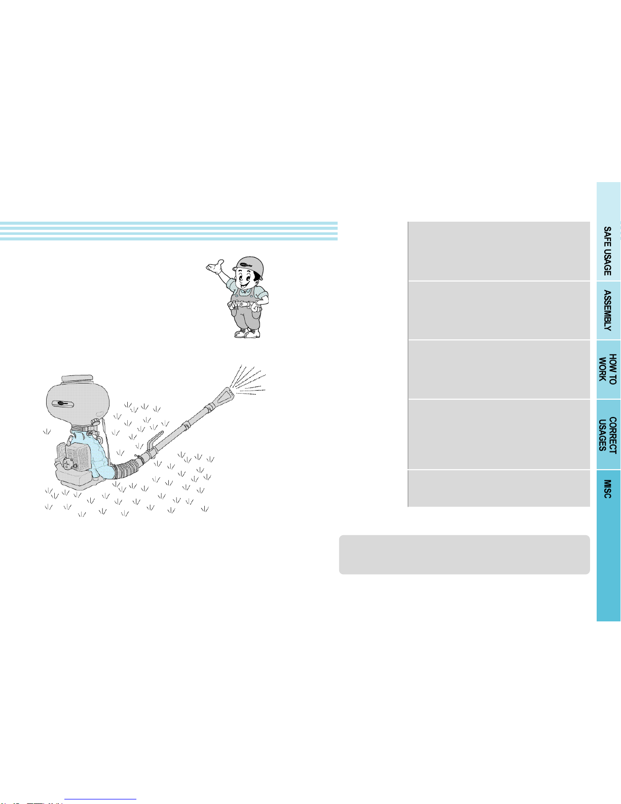
In order to prevent accidents that can happen easily while using or handling the power mist & duster, and also
for safe work, the Safety Instructions consist of Clothing, Environment, Fire hazards, Pre-operation stages,
Operational stages and Postoperation stages. These warnings and cautionary instructions for safety cannot
cover all possible situations or conditions that can happen. Therefore, scrupulous cares are needed when
operating or storing the product. Please read completely and understand. And be careful so that accident does
not occur.
In the event the instruction
is not followed, it is
possible that serious injury
or death may occur highly.
In the event the instruction
is not followed, it is
possible that serious injury
or death may occur.
In the event the instruction is not
followed, it is possible that troubles,
which can disable or degrade the
product performance, may occur.
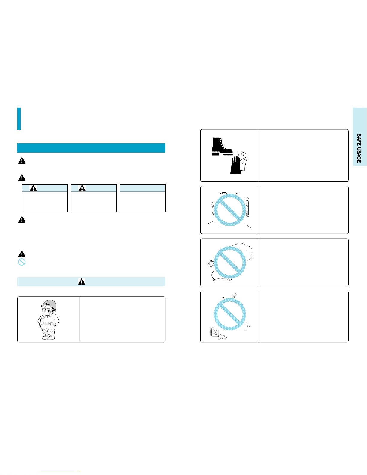
CautionWarning Caution
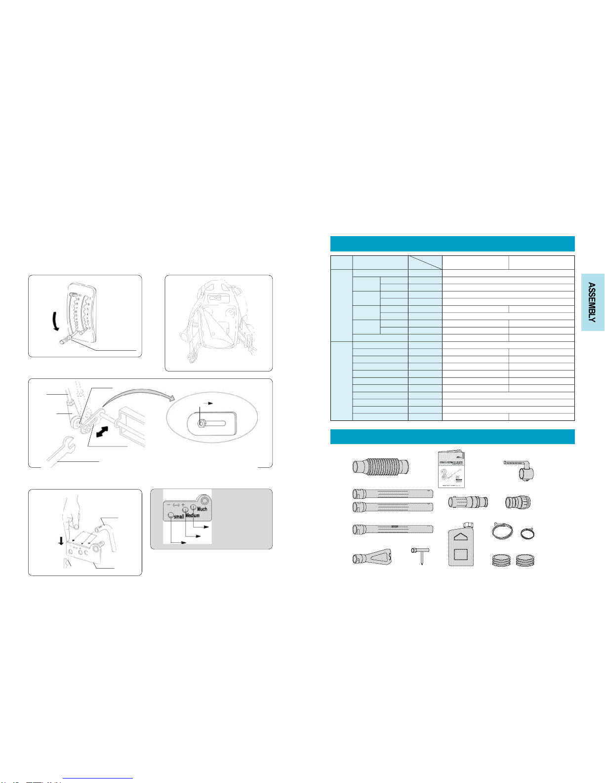
When working, wear the following protective
gears.
■To protect head, wear safety hat.
■To protect eyes, wear safety glasses.
■To protect ears, wear earmuffs.
■Wear knee protectors.
If protective gears were not worn, flying objects such as
rocks can cause injuries.
Warning
1. SAFE USAGE
※
Illustrative signs used on the product and in the handling instructions are as follows:
This sign means“Care is needed”because there are possibilities that danger may occur under certain conditions.
This sign means“Prohibited”because there are possibilities that danger may occur under certain conditions.
4 5
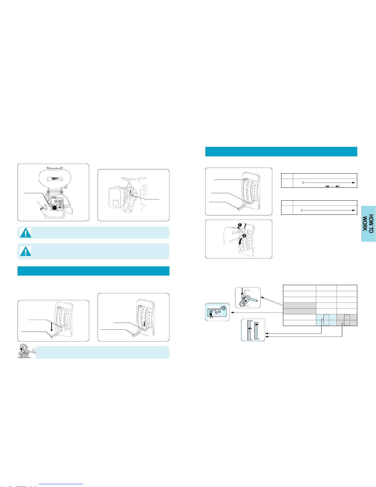
Wear clothing that is suitable for work.
■Wear slip resistant safety shoes.
■Wear gloves when working.
■Tie long hairs above shoulders.
■Do not wear hanging down clothes, neckties, scarves,
or ribbons.
Working with unsuitable clothing can become a cause of
accident by slipping, getting burned, or getting caught in
the machine while working.
Do not use the tool in indoors or where ventilation is
poor.
Do not use when you are unable to operate the
product normally due to alcohol, drug or
anything else.
■It can causes a safety accident.
Be careful to the flammable.
■It can causes serious injury.

6
Do not open the fuel tank cap or refuel while the
engine is running or when the engine is hot.
■It can cause fire or burn.
Due to medicine, humidity and temperature, a
strong static electricity might happen.
Be sure to use earth chain for safety.
Do not use when it is raining.
■It can cause electric shock and an accident by slipping.
The old and the weak or children should
not use.
■Unskilled use can become a cause for an
accident.
Never spray toward man or animal.
■It can cause serious injury.
If fuel is spilled, wipe it off thoroughly.
■Spilled fuel can stain clothing or cause a fire.
If there is any abnormal vibration while
operating, stop the engine immediately.
■It can cause a breakdown of the machinery or can cause
an accident.
7
Be sure to start working over 3m away from
flame when engine starts.
CAUTION

Be sure to place engine on flat ground when
you start the engine.
Do not pull the recoil starter after the engine
start
■Engine kickback can be transmitted to the recoil
starter, and it can cause serious personal injury.
With engine back shoulder, never start!!
Do not start the engine with backpacking.
8
When storing for a long-term(more than 20 days),
always drain fuel before storing.
■If stored with fuel undrained, it will become difficult to
start the next time due to the settled deposits in fuel
passages.
CAUTION
9
Observe the mixture ratio of the fuel.
■Observe the mixture ratio of 20~25 parts of Gasoline to
1 part of 2-cycle engine oil. Too much oil causes smoky
exhaust fume and decrease the output power. Too little
oil can damage the engine due to excessive heat.
Be sure to check every tightness of nuts and
other parts before machine starting
Do not touch the engine until it cools down
■There are many parts that radiate large amount of heat
such as muffler, etc. These parts remain hot even after
the engine is turned off and can cause burns.
Gasoline
and oil
mix ratio
25:1

2. ASSEMBLY
1. Assembling of jet pipe
11
1. Put the rubber packing (big) between the
right groove of the operating elbow.
(Above mentioned rubber packing (big) is
usually sold under condition of assembled.
2. Put the wire clamp big in standard parts
between outer part of the rumpled pipe as
figure shown.
3.After assembling as figure shown the
corrugated pipe with wire clamp holding to
elbow, wire clamp (big) shall be tightened by
hand strongly.(When assembles the
corrugated pipe to elbow, it is much
convenient for applying oil or water on the
surface of rubber packing.)
When you tighten the wire clamp, do not use any hand tool or other tools. Rubber packing
or the corrugated pipe might be damaged.
In order to avoid a
interference with your arm,
locate the wire clamp screw
downward.
•REGARDING HOW TO ASSEMBLE
10
Chemical tank cap
Trumpet pipe
Straight pipe
Close area spraying pipe
Straight pipe(A)
Connector pipe
Wire clamp(Small)
Corrugated pipe
Engine Wire clamp (Big)
Muffler
Handle Ass’y
Shoulder band
Cushion pad
Clamp
Frame
Air cleaner Fuel tank Frame
Recoil starter
Earth chain
Carburetor
Control panel
Throttle lever
Volume control lever
•PARTS NAMES
Chemical tank
Rubber packing (big)
Electric wire
Elbow
Rubber packing (big) Corrugated pipe
Electric wire
Wire bolt Wire clamp (big)
Corrugated pipe
Wire clamp screw(downward)
Electric wire
Wire clamp(big)

13
1. Assemble the guide pipe to the working unit in
same direction as figure.(This time, be careful
not to spill the chemical during working, when
getting wrinkled in rubber packing of guide
pipe.)
2. Put the chemical tank between the working unit
correctly in direction attached this product
brand.
3. In condition the chemical tank putting in, both
clamps in working unit must be set the chemical
tank by turning as figure.
Electric wire should be set with tape below with letting it pass through jet hose.
Vinyl hose
Plunger ring Rubber packing(small)
Chemical tank
Guide pipe
Clamp
Wire clamp(small) Electric wire Jet hose
1. The rubber packing (small)
between the part of jet hose.
2. Assemble the plunger ring in
direction as figure after setting the
packing.
3. Put the wire clamp (small)
between the outer part of
corrugated pipe. (This time it is
much convenient for applying oil
or water on rubber packing
surface.
4. After putting the assembled jet
hose between inside the
corrugated pipe, be sure to set the
clamp wire bolt tightly by hand.
5. With putting the agricultural vinyl
hose for powder in advance
between the jet hose plunger ring
and jet hose, the plunger ring
should be set pushing tightly in
arrow direction as figure.
Plunger ring
Working unit
12
4. Please assemble connector pipe,
rubber packing (small), and wire
clamp (small) same as the method
of 1. and 2. described
Let the electric wire pass through
in connector pipe, and be sure to
set it with tape of something else
on proper position below it.
5. Connector pipe, handle
After putting the middle pipe
between connector pipe, please
assemble the handle on proper
position.
Be sure to check the locking position absolutely.
6. Please use the other straight pipe or close jet pipe with proper assembling for suitable usage.
직선관 근거리분사관 나팔관
직선관
▼Complete assembling figure
In order to avoid a interference
with your arm, locate the wire
clamp screw downward.
2. Jet hose assembly
3. Assembly with chemical tank
Connector pipe
Connector pipe handle
Electric wire
Rubber packing big
Wire clamp(small)
Straight pipe Close jet pipe bent pipe
Straight pipe

14 15
1. Put the volume control lever to the zero position. 2. Separate the cushion pad attached in front of
back panel as figure shown.
3. After putting the hinge bolt in arm, set twist with spanner.
4. After pushing the link as below figure, setting pin must put in the hole of middle rod.
Volume control lever
Standard
When spraying small
volume
Hinge bolt
Middle rod
Hinge
10mm spanner
Push
slightly
Middle rod
Link
Setting pin
Volume control arm
Small
Medium
Much
For powder spray
For fertilizer spray
For Granule agricultural medicine spray
4. Volume control assembly
•PRODUCT SPECIFICATIONS
•STANDARD PARTS
Corrugated pipe
Straight pipe
Close area spraying pipe
Box & driverTrumpet pipe Fuel mixing tank Rubber packing(small)
Wire clamp(Big) Wire clamp(Small)
Jet hose
Connector pipe ass’y
Instruction manual
Division Item
KPB-6030DM/6030D/6030 KPB-7030DM/7030D/7030
Working
Machine
Engine
Chemical Tank
Capacity
Blower
Belching
volume
Belching
distance
Size(Length×Width×Height)
Powder
Liquid
Type
rotation
powder
Granule
Maxium
Effective distance
mm
l
l
rpm
kg/min
kg/min
m
m
kg
cc
ps/rpm
kg·m/rpm
kg
l
450×500×800
30
25
Multi-wing centrifugal blower
7,500
2.56 6
12(agricultural medicine)~18(fertilizer)
24 25
18 19
12 12.4
Forced air-cooled 2 cycle, 1 cylinder
Unleaded gasoline + 2cycle lubricant oil
20~25:1
2.0
Weight
Type
Maker
Model
Displacement
Max. power
Max. torque
Dry. weight
Fuel
Fuel mixing rate
Fuel tank capacity
Spark plug
Unit Type
Mitzubishi(Japan)
T320PSD-SAK
49.4
3.2 / 7,500
0.3 / 6,000
3.2
NGK BM-7A equivalent NGK BPM-7A equivalent
Kawasaki(Japan)
TE059M-AT54
59.2
4.2 / 7,500
0.38 / 5,000
3.6
Handle ass’y

17
1. With the volume control lever downed to zero position,
the throttle lever must be set to 4 or 5 position. 2. Push the priming pump over 10 times be sure to
check if any leakage of fuel hose and connection
3. Choke lever must be adjusted.
When the first start or engine getting coole
When the engine getting heated
Close
Open
Choke lever
Volume control lever
Throttle lever
3. HOW TO WORK
•시동
1. Mix gasoline and lub. Oil up to described line.
The mixing rate for gasoline and lub oil should be kept
absolutely.
(Gasoline : lub oil=20~25:1)
2. After closing the fuel cap, please shake it several times for
getting well mixed.
3. The mixed fuel must be filled to the fuel tank with cap opened.
If the fuel overflows or spills, it must be cleaned.
It might happen the clothes getting dirty or fire
danger.
Keep mixing rate, if not, it might happen engine
damage. Use the lub. oil for 2 cycle engine.
16
If it is getting loosed, the
medicine might be spilled
when working.
1. The volume control lever
moves down to zero position as
figure shown.
3. After putting in the chemical,
the medicine tank cover
should be tightened by hand
for not getting loosed.
2. After opening the cap of chemical
tank, the medicine prepared is put
into.
•HOW TO START THE ENGINE
1. Preparation before start
3. Start
2. Supply
Gasoline

19
Throttle lever(Engine speed control)
0 1 2 3 4 5 6 7Stage
Speed Stop
Low speed High speed
Starting position
0 1 2 3 4 5 6 7 8 9 10Stage
Speed
Closing
Small
Volume control lever
(Adjusting the volume of medicine spray)
Volume stopper
Volume stopper is a device to prevent from over-spray
of the medicine.
Set the button at suitable position by moving up and
down after pulling the button as shown
1. Granule agricultural chemical spray ※Walking at 10 meter per 18 seconds
small
little amount
standard
Volume stopper
Throttle lever
Volume control lever
Big
10a spray volume
Spray width(m)
Ventilation volume(kgf/min)
Volume control arm
Link arm
Volume control lever
Throttle lever
3kg
13
1.2
little amount
small
6
6
4kg
13
1.2
little amount
small
6
6
•WORKING TECHNIQUES
18
4. With the recoil start lever pulled, start engine. 5. When operates in hot weather, the choke lever must
move down for low speed operation.
1. Set the volume control lever to zero position, after
rotation (1 or 2 stage) at low speed condition for
about 1 or 2 minutes, the medicine remained in unit
must be sprayed out at all.
2. After idling 1 or 2 minutes, the throttle lever must be
set to zero position for engine stop.
When the engine starts, the unit should be putting on flat ground.
With hanging on the shoulder, do not start the engine.
Before engine starts, be sure to check the direction of the jet pipe; the earth chain should be used in advance.
For prevention of the static electricity, the earth chain should be used in advance.
Choke lever
Recoil start
lever
Throttle lever
Volume control lever
After the engine stop, do not close the volume control lever.
Because there might be serious damage on the shuttle gate rubber due to medicine sticking
on it in the tank.
Throttle leve
Volume control lever
Do not touch with the muffler or body of the engine while the engine is run or stopped.
You may get burned.
•HOW TO TURN OFF THE ENGINE
1.How to control panel
2. How to control vlume of spray

21
4. CORRECT USAGES
Guide pipe
1. With the chemical tank separated, remove the
medicine inside the tank. 2. From the unit taking out the guide pipe, please clean
inside the pipe with the guide pipe
3. Wash clean the medicine tank inside with dry cloth
for removing the remained.
5. With lowest speed rotating slightly for 2 or 3
minutes, please belch out the chemical remained in
the tank.
4. Be sure to clean with oiled cloth the all metal parts of
the unit.
Be sure to be careful for not happen
metal erosion by the chemical reaction of
the medicine especially.
•MAINTENANCE AND LONG-TERM STORAGE
20
2. Graunle chemical spray
3. Powder agricultural chemical spray
■During injecting chemicals, if possible, inject whole chemicals in the chemicals tank.
■When completing the operation with the chemicals in the tank left, you must withdraw whole chemicals
in the tank.
■Never close the injection control lever forcibly with the chemicals in the tank left. Fertilizer in the shuttle
gate may result in trouble.
little amount
standard
medium
※Walking at 10 meters per 18 seconds
10a spray volume
Spray width(m)
Ventilation volume(kgf/min)
Volume control arm
Link arm
Volume control lever
Throttle lever
10kg
20
6.5
standard
medium
5
6
10kg
20
6.5
standard
medium
6
6
little amount
standard
medium
10a spray volume
Spray width(m)
Ventilation volume(kgf/min)
Volume control arm
Link arm
Volume control lever
Throttle lever
3kg
60m vynil hose
3
standard
much
7
6
4kg
50m vynil hose
3
standard
much
8
6
1. Cleaning

5. Spark plug
1. After taking out the plug cap, the
spark plug may be twisted out with
box driver of standard parts.
2. With soft brush it is cleaned the
polluted at plug igniting part as
figure shown.
3. The gap of igniting tip must be
0.6~0.7mm. After checking it
correctily, it is exchanged when
gets some strange.
When engine does not start, the spark plug should be checked.
6. Muffler
The carbon in muffler should be removed.
For regular guarantee of engine function, this checking
must be doing periodically.
Unit
Engine
Pan case bolt joint condition
Shoulder belt bolt damage condition
Control panel bolt joint condition
Lubrication each metal parts
Air cleaner wash
Exchange the fuel strainer
Cleaning the spark plug
Removing the carbon in muffler
◎
◎
◎
◎
◎ ◎
◎
◎
◎
Inspecting and maintenance
Items Checking and checking cycle
Before work After work 2 months 6 months 1 years 2 years
23
•
THE DIAGRAM FOR INSPECTION AND MAINTENANCE
1. After lubrication to each spindle of
control panel, try to move 4 or 5
times the lever up and down
2. After lubrication to clamp of the
chemical tank, try to move
clamp 4 or 5 times.
3. Check the each bolt and nut
getting loosened, and all the
loosened bolts and nuts should be
tightened with tool like spanner.
3. Engine
●Air cleaner
4. Fuel strainer
1. Air cleaner is dismantled as figure
shown. 2. After rinsing the fillter into
clean kerosene for 2 or 3
minutes, fumble it by hand 5 or
6 times
3. After squeezing the kerosene
wet filter by hand, get dry it for
1 or 2 minutes in shadow.
Filter
Cover
Net supporter
When air cleaner filter gets dirty, the engine power might get weakened or no start moving be sure to
check periodically.
■When the fuel strainer get polluted, there might
happen not smootly engine start or the engine
function gets weakened. Be sure to be checked it
periodically.
■Be sure to use the Keyang genuine parts without fail.
1. With opened the fuel tank cap,
with wire using take out the fuel strainer
2. In case of heavy polluted the fuel strainer,
should get changed for a new one.
22
2. Working unit
Clearance

25
Drain cap
Spray pipe
Volume control lever
Throttle lever
5. The chemical tank cap and drain cap must be
loosened. 6. Set the throttle lever at 0 position and the volume
control lever at 10 position.
7. Dissemble the spray pipe. 8. After putting in packing box, it should be kept in a
cool place.
1. As the main points for clean and checking in 8
column, each part of the machine should be
cleaned and maintained.
2. The fuel remained in fuel tank should be
removed.
3. After removing the spark plug, engine lub oil must be
put suitable amount (about 5cc), then, pull the recoil
start 2 or 3 times
4. After reassembling the spark plug, the recoil start
should be pulled 3 or 4 time.
24
•LONG TERM STORAGE
When you keep the engine for a long period (more than 30 days), you must remove fuel in the engine.
When you keep the engine with fuel, there will be the deposit in the fuel line. Also, it may casue poor
starting.
When you rest or stop work for a while.
Place the engine level, leakage of fuel at inclined position can cause a fire.

Filter
Net supporter
Cover
Engine will not
start
Problem Check Action
Medicine leaks
between
corrugated pipe
connecotr
Cannot spray
medicine
Engine lacks
power or stall
Engine will not idle
Choke in incorrect positin
Empty fuel tank
Primer bulb wasn’t pushed enough
Carburetor misadjusted
Throttle wire has come loose
Dirty air filter
No oil in fuel
Tank clogged with medicine
Guide pipe clogged with medicine
Rubber packing is damaged
Wire clamp has come loose
Refer to starting/stopping instructions
on page 17
Fill fuel tank
Press primer bulb fully and sloowly until fuel is
visible in bulb
Adjust carburetor
Adjust carburetor
Clean or replace air fillter
Add oil to fuel (25(gasoline) : 1(oil for 2 cycle engine))
Clean the tank
Romove medicine in the guide pipe
Check or replace rubber packing
Adjust and tighten wire clamp
26
•BEFORE YOU CALL FOR SERVICE
It is dangerous for consumers to troubleshoot or repair for themselves for abnormal engine. Please
call for A/S center and follow the istructions.
MEMO

2002.9.30
823-2 Wonsi-dong, Ansan-shi, Kyouggi-do, KOREA
Tel : Int+82-31-490-3000 Fax : Int+82-31-490-3019
This manual suits for next models
5
Table of contents
Popular Blower manuals by other brands

Black & Decker
Black & Decker BV2500 instruction manual

Haaga
Haaga 375 Original operating instructions

Homelite
Homelite ZR08107 Operator's manual

Becker
Becker SV 1100 operating instructions

Stiga
Stiga SAB 900 AE Operator's manual

Harbor Freight Tools
Harbor Freight Tools 65003 Set up and operating instructions

Kärcher
Kärcher AB 30 Classic manual

Scheppach
Scheppach SC2200PE Translation of original instruction manual

Little Wonder
Little Wonder 9600, 9810, 9900, 9100, 9130 Owner's manual and safety instructions

Makita
Makita BUB360 instruction manual

Husqvarna
Husqvarna 578BTF Operator's manual

Coopers of Stortford
Coopers of Stortford F916 Instructions for use