Keysight Technologies N5511A User manual

Getting Started
Guide
Keysight N5511A
Phase Noise Test System

Notices
© Keysight Technologies, Inc. 2019
No part of this manual may be
reproduced in any form or by any
means (including electronic storage
and retrieval or translation into a
foreign language) without prior
agreement and written consent from
Keysight Technologies, Inc. as
governed by United States and
international copyright laws.
Trademark Acknowledgments
Manual Part Number
N5511-90001
Edition
Edition 1, September 2019
Printed in USA/Malaysia
Published by:
Keysight Technologies
1400 Fountaingrove Parkway
Santa Rosa, CA 95403
Warranty
THE MATERIAL CONTAINED IN THIS
DOCUMENT IS PROVIDED “AS IS,”
AND IS SUBJECT TO BEING
CHANGED, WITHOUT NOTICE, IN
FUTURE EDITIONS. FURTHER, TO
THE MAXIMUM EXTENT PERMITTED
BY APPLICABLE LAW, KEYSIGHT
DISCLAIMS ALL WARRANTIES,
EITHER EXPRESS OR IMPLIED WITH
REGARD TO THIS MANUAL AND
ANY INFORMATION CONTAINED
HEREIN, INCLUDING BUT NOT
LIMITED TO THE IMPLIED
WARRANTIES OF
MERCHANTABILITY AND FITNESS
FOR A PARTICULAR PURPOSE.
KEYSIGHT SHALL NOT BE LIABLE
FOR ERRORS OR FOR INCIDENTAL
OR CONSEQUENTIAL DAMAGES IN
CONNECTION WITH THE
FURNISHING, USE, OR
PERFORMANCE OF THIS
DOCUMENT OR ANY INFORMATION
CONTAINED HEREIN. SHOULD
KEYSIGHT AND THE USER HAVE A
SEPARATE WRITTEN AGREEMENT
WITH WARRANTY TERMS
COVERING THE MATERIAL IN THIS
DOCUMENT THAT CONFLICT WITH
THESE TERMS, THE WARRANTY
TERMS IN THE SEPARATE
AGREEMENT WILL CONTROL.
Technology Licenses
The hardware and/or software
described in this document are
furnished under a license and may be
used or copied only in accordance
with the terms of such license.
U.S. Government Rights
The Software is “commercial
computer software,” as defined
by Federal Acquisition Regulation
(“FAR”) 2.101. Pursuant to FAR
12.212 and 27.405-3 and
Department of Defense FAR
Supplement (“DFARS”) 227.7202,
the U.S. government acquires
commercial computer software
under the same terms by which
the software is customarily
provided to the public.
Accordingly, Keysight provides
the Software to U.S. government
customers under its standard
commercial license, which is
embodied in its End User License
Agreement (EULA), a copy of
which can be found at
http://www.keysight.com/find/sweula
The license set forth in the EULA
represents the exclusive authority
by which the U.S. government
may use, modify, distribute, or
disclose the Software. The EULA
and the license set forth therein,
does not require or permit,
among other things, that
Keysight: (1) Furnish technical
information related to
commercial computer software
or commercial computer
software documentation that is
not customarily provided to the
public; or (2) Relinquish to, or
otherwise provide, the
government rights in excess of
these rights customarily provided
to the public to use, modify,
reproduce, release, perform,
display, or disclose commercial
computer software or
commercial computer software
documentation. No additional
government requirements
beyond those set forth in the
EULA shall apply, except to the
extent that those terms, rights, or
licenses are explicitly required
from all providers of commercial
computer software pursuant to
the FAR and the DFARS and are
set forth specifically in writing
elsewhere in the EULA. Keysight
shall be under no obligation to
update, revise or otherwise
modify the Software. With
respect to any technical data as
defined by FAR 2.101, pursuant
to FAR 12.211 and 27.404.2 and
DFARS 227.7102, the U.S.
government acquires no greater
than Limited Rights as defined in
FAR 27.401 or DFAR 227.7103-5
(c), as applicable in any technical
data.
Safety Notices
A CAUTION notice denotes a hazard. It
calls attention to an operating
procedure, practice, or the like that,
if not correctly performed or adhered
to, could result in damage to the
product or loss of important data. Do
not proceed beyond a CAUTION
notice until the indicated conditions
are fully understood and met.
A WARNING notice denotes a hazard.
It calls attention to an operating
procedure, practice, or the like that,
if not correctly performed or adhered
to, could result in personal injury or
death. Do not proceed beyond a
WARNING notice until the indicated
conditions are fully understood and
met.

3
Where to Find the Latest Information
Documentation is updated periodically. For the latest information about these products, including instrument software
upgrades, application information, and product information, browse to the following URL:
http://www.keysight.com/find/n5511a
To receive the latest updates by email, subscribe to Keysight Email Updates at the following URL:
http://www.keysight.com/find/MyKeysight
Information on preventing instrument damage can be found at:
www.keysight.com/find/PreventingInstrumentRepair
Is your product software up-to-date?
Periodically, Keysight releases software updates to fix known defects and incorporate product enhancements. To search
for software updates for your product, go to the Keysight Technical Support website at:
http://www.keysight.com/find/techsupport

4

Contents
Keysight N5511A Phase Noise Test System 5
Table of Contents
1. Initial Setup
Introduction. . . . . . . . . . . . . . . . . . . . . . . . . . . . . . . . . . . . . . . . . . . . . . . . . . . . . . . . . . . . . . . . . . . . . . . . . . . . . . . . . . 8
Unpacking and Inspecting the System. . . . . . . . . . . . . . . . . . . . . . . . . . . . . . . . . . . . . . . . . . . . . . . . . . . . . . . . . . . . . 9
To unpack a benchtop system . . . . . . . . . . . . . . . . . . . . . . . . . . . . . . . . . . . . . . . . . . . . . . . . . . . . . . . . . . . . . . . 9
Verify shipping contents . . . . . . . . . . . . . . . . . . . . . . . . . . . . . . . . . . . . . . . . . . . . . . . . . . . . . . . . . . . . . . . . . . . 10
Remove Shipping Cover . . . . . . . . . . . . . . . . . . . . . . . . . . . . . . . . . . . . . . . . . . . . . . . . . . . . . . . . . . . . . . . . . . . 11
System Components . . . . . . . . . . . . . . . . . . . . . . . . . . . . . . . . . . . . . . . . . . . . . . . . . . . . . . . . . . . . . . . . . . . . . . 12
Making Connections . . . . . . . . . . . . . . . . . . . . . . . . . . . . . . . . . . . . . . . . . . . . . . . . . . . . . . . . . . . . . . . . . . . . . . . . . . 13
Before connecting the cables to any device: . . . . . . . . . . . . . . . . . . . . . . . . . . . . . . . . . . . . . . . . . . . . . . . . . . . 13
Proper Connector Torque . . . . . . . . . . . . . . . . . . . . . . . . . . . . . . . . . . . . . . . . . . . . . . . . . . . . . . . . . . . . . . . . . . 13
Connecting a Display to your System. . . . . . . . . . . . . . . . . . . . . . . . . . . . . . . . . . . . . . . . . . . . . . . . . . . . . . . . . 14
Powering the System On . . . . . . . . . . . . . . . . . . . . . . . . . . . . . . . . . . . . . . . . . . . . . . . . . . . . . . . . . . . . . . . . . . . . . . 15
To power on a racked system . . . . . . . . . . . . . . . . . . . . . . . . . . . . . . . . . . . . . . . . . . . . . . . . . . . . . . . . . . . . . . . 15
Starting the Measurement Software . . . . . . . . . . . . . . . . . . . . . . . . . . . . . . . . . . . . . . . . . . . . . . . . . . . . . . . . . . . . . 16
Verify License Key is Installed . . . . . . . . . . . . . . . . . . . . . . . . . . . . . . . . . . . . . . . . . . . . . . . . . . . . . . . . . . . . . . . 18
Asset Manager . . . . . . . . . . . . . . . . . . . . . . . . . . . . . . . . . . . . . . . . . . . . . . . . . . . . . . . . . . . . . . . . . . . . . . . . . . . . . . 19
Configuring an Asset . . . . . . . . . . . . . . . . . . . . . . . . . . . . . . . . . . . . . . . . . . . . . . . . . . . . . . . . . . . . . . . . . . . . . . 19
Powering the System Off . . . . . . . . . . . . . . . . . . . . . . . . . . . . . . . . . . . . . . . . . . . . . . . . . . . . . . . . . . . . . . . . . . . . . . 25
2. General Information
System Overview. . . . . . . . . . . . . . . . . . . . . . . . . . . . . . . . . . . . . . . . . . . . . . . . . . . . . . . . . . . . . . . . . . . . . . . . . . . . . 28
System Specifications. . . . . . . . . . . . . . . . . . . . . . . . . . . . . . . . . . . . . . . . . . . . . . . . . . . . . . . . . . . . . . . . . . . . . . . . . 32
Power requirements. . . . . . . . . . . . . . . . . . . . . . . . . . . . . . . . . . . . . . . . . . . . . . . . . . . . . . . . . . . . . . . . . . . . . . . 34
Equipment Installation . . . . . . . . . . . . . . . . . . . . . . . . . . . . . . . . . . . . . . . . . . . . . . . . . . . . . . . . . . . . . . . . . . . . . . . . 35
Test Set Location and Mounting Requirements . . . . . . . . . . . . . . . . . . . . . . . . . . . . . . . . . . . . . . . . . . . . . . . . . 36
N5511A Rack Mount Instructions (Optional) . . . . . . . . . . . . . . . . . . . . . . . . . . . . . . . . . . . . . . . . . . . . . . . . . . . . . . . 37
Keysight Y1215C Flush Mount Rack Kit . . . . . . . . . . . . . . . . . . . . . . . . . . . . . . . . . . . . . . . . . . . . . . . . . . . . . . . 37
General Rack Mounting Guidelines . . . . . . . . . . . . . . . . . . . . . . . . . . . . . . . . . . . . . . . . . . . . . . . . . . . . . . . . . . 37
Assembly and Installation . . . . . . . . . . . . . . . . . . . . . . . . . . . . . . . . . . . . . . . . . . . . . . . . . . . . . . . . . . . . . . . . . . 39
Documentation . . . . . . . . . . . . . . . . . . . . . . . . . . . . . . . . . . . . . . . . . . . . . . . . . . . . . . . . . . . . . . . . . . . . . . . . . . . . . . 47
Contacting Keysight Technologies . . . . . . . . . . . . . . . . . . . . . . . . . . . . . . . . . . . . . . . . . . . . . . . . . . . . . . . . . . . . . . . 48
3. System Interconnections
N5511A System Modules . . . . . . . . . . . . . . . . . . . . . . . . . . . . . . . . . . . . . . . . . . . . . . . . . . . . . . . . . . . . . . . . . . . . . . 50
N5511A Two Channel Cable Connections . . . . . . . . . . . . . . . . . . . . . . . . . . . . . . . . . . . . . . . . . . . . . . . . . . . . . . . . . 51
4. Making a Measurement
Making a Single Channel Absolute Phase Noise Measurement . . . . . . . . . . . . . . . . . . . . . . . . . . . . . . . . . . . . . . . . 58
Equipment Needed . . . . . . . . . . . . . . . . . . . . . . . . . . . . . . . . . . . . . . . . . . . . . . . . . . . . . . . . . . . . . . . . . . . . . . . 58
Connections. . . . . . . . . . . . . . . . . . . . . . . . . . . . . . . . . . . . . . . . . . . . . . . . . . . . . . . . . . . . . . . . . . . . . . . . . . . . . 58
Configuring Equipment . . . . . . . . . . . . . . . . . . . . . . . . . . . . . . . . . . . . . . . . . . . . . . . . . . . . . . . . . . . . . . . . . . . . 59
Measurement Procedure . . . . . . . . . . . . . . . . . . . . . . . . . . . . . . . . . . . . . . . . . . . . . . . . . . . . . . . . . . . . . . . . . . . 60
New Measurement . . . . . . . . . . . . . . . . . . . . . . . . . . . . . . . . . . . . . . . . . . . . . . . . . . . . . . . . . . . . . . . . . . . . . . . 71

6 Keysight N5511A Phase Noise Test System
Contents
5. Recovery
Hard Drive Recovery Process . . . . . . . . . . . . . . . . . . . . . . . . . . . . . . . . . . . . . . . . . . . . . . . . . . . . . . . . . . . . . . . . . . . 78
Configuring recovery prompt timing. . . . . . . . . . . . . . . . . . . . . . . . . . . . . . . . . . . . . . . . . . . . . . . . . . . . . . . . . . 80
SSD Replacement Procedure . . . . . . . . . . . . . . . . . . . . . . . . . . . . . . . . . . . . . . . . . . . . . . . . . . . . . . . . . . . . . . . . . . . 81
Removing the SSD . . . . . . . . . . . . . . . . . . . . . . . . . . . . . . . . . . . . . . . . . . . . . . . . . . . . . . . . . . . . . . . . . . . . . . . 81
6. Service, Support, and Safety Information
Safety and Regulatory Information . . . . . . . . . . . . . . . . . . . . . . . . . . . . . . . . . . . . . . . . . . . . . . . . . . . . . . . . . . . . . . 84
General . . . . . . . . . . . . . . . . . . . . . . . . . . . . . . . . . . . . . . . . . . . . . . . . . . . . . . . . . . . . . . . . . . . . . . . . . . . . . . . . 84
Before Applying Power . . . . . . . . . . . . . . . . . . . . . . . . . . . . . . . . . . . . . . . . . . . . . . . . . . . . . . . . . . . . . . . . . . . . 84
Ground the Instrument . . . . . . . . . . . . . . . . . . . . . . . . . . . . . . . . . . . . . . . . . . . . . . . . . . . . . . . . . . . . . . . . . . . . 84
Do Not Operate in an Explosive Atmosphere . . . . . . . . . . . . . . . . . . . . . . . . . . . . . . . . . . . . . . . . . . . . . . . . . . . 85
Do Not Operate Near Flammable Liquids . . . . . . . . . . . . . . . . . . . . . . . . . . . . . . . . . . . . . . . . . . . . . . . . . . . . . 85
Cleaning . . . . . . . . . . . . . . . . . . . . . . . . . . . . . . . . . . . . . . . . . . . . . . . . . . . . . . . . . . . . . . . . . . . . . . . . . . . . . . . 85
Do Not Remove Instrument Cover . . . . . . . . . . . . . . . . . . . . . . . . . . . . . . . . . . . . . . . . . . . . . . . . . . . . . . . . . . . 85
Keep Away from Live Circuits . . . . . . . . . . . . . . . . . . . . . . . . . . . . . . . . . . . . . . . . . . . . . . . . . . . . . . . . . . . . . . . 85
Do Not Operate Damaged Equipment . . . . . . . . . . . . . . . . . . . . . . . . . . . . . . . . . . . . . . . . . . . . . . . . . . . . . . . . 85
Do Not Block the Primary Disconnect . . . . . . . . . . . . . . . . . . . . . . . . . . . . . . . . . . . . . . . . . . . . . . . . . . . . . . . . 86
Do Not Modify the Instrument . . . . . . . . . . . . . . . . . . . . . . . . . . . . . . . . . . . . . . . . . . . . . . . . . . . . . . . . . . . . . . 86
In Case of Damage . . . . . . . . . . . . . . . . . . . . . . . . . . . . . . . . . . . . . . . . . . . . . . . . . . . . . . . . . . . . . . . . . . . . . . . 86
Safety Symbols and Instrument Markings . . . . . . . . . . . . . . . . . . . . . . . . . . . . . . . . . . . . . . . . . . . . . . . . . . . . . 87
Regulatory Compliance. . . . . . . . . . . . . . . . . . . . . . . . . . . . . . . . . . . . . . . . . . . . . . . . . . . . . . . . . . . . . . . . . . . . 89
Service and Support . . . . . . . . . . . . . . . . . . . . . . . . . . . . . . . . . . . . . . . . . . . . . . . . . . . . . . . . . . . . . . . . . . . . . . . . . . 90
Service and Support Options . . . . . . . . . . . . . . . . . . . . . . . . . . . . . . . . . . . . . . . . . . . . . . . . . . . . . . . . . . . . . . . 90
Contacting Keysight Technologies . . . . . . . . . . . . . . . . . . . . . . . . . . . . . . . . . . . . . . . . . . . . . . . . . . . . . . . . . . . 91
Return Procedure . . . . . . . . . . . . . . . . . . . . . . . . . . . . . . . . . . . . . . . . . . . . . . . . . . . . . . . . . . . . . . . . . . . . . . . . . . . . 92
Determining your instrument’s serial number . . . . . . . . . . . . . . . . . . . . . . . . . . . . . . . . . . . . . . . . . . . . . . . . . . 92
Shipping Your Analyzer to Keysight for Service or Repair . . . . . . . . . . . . . . . . . . . . . . . . . . . . . . . . . . . . . . . . . 92

7
Keysight N5511A Phase Noise Test System
Getting Started Guide
1 Initial Setup
“Introduction” on page 8
“Unpacking and Inspecting the System” on page 9
“Making Connections” on page 13
“Powering the System On” on page 15
“Starting the Measurement Software” on page 16
“Asset Manager” on page 19
“Powering the System Off” on page 25

8 N5511A Phase Noise Test System Getting Started Guide
Initial Setup
Introduction
Introduction
Use this guide to unpackage and set up your benchtop N5511A Phase noise
test system.
Check all the cable connections to the Phase detector, Data Converter and
Reference modules.
Power on the N5511A unit for the first time. The N5511A system will arrive with
the instrument software and licenses already installed. Before making your first
measurement, you should check the installed assets and add any additional
assets to the system.
After adding the reference sources (spectrum analyzer and oscilloscope (not
required)) to the system, perform the first measurement. Perform the system
functional check by making an Absolute Phase Noise Measurement as your
first measurement.
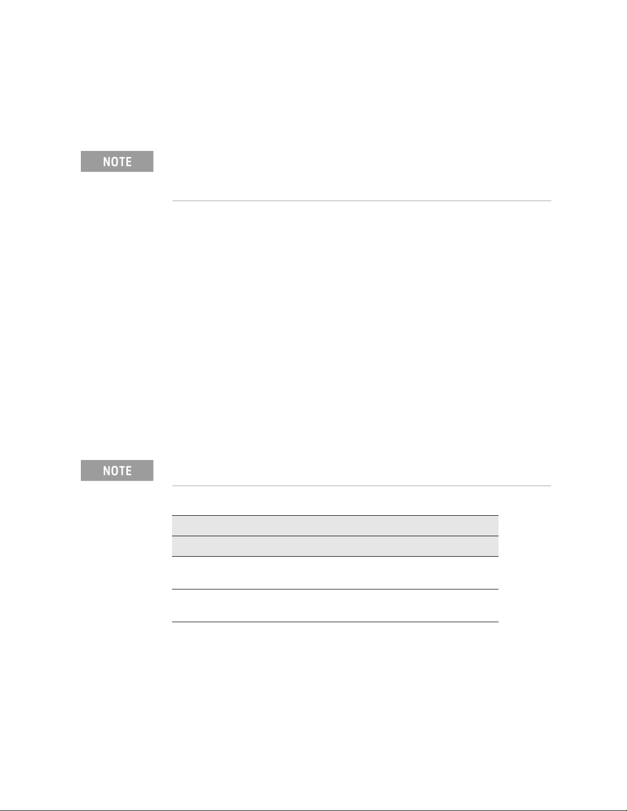
Use Table 1-1 as a guide to the chapters to use for your benchtop system:
If you need to upgrade the phase noise software in the N5511A system controller for any reason,
refer to the N5511A Phase Noise Test System User’s Guide for information and procedures.
Table 1-1 N5511A installation reading road map
Benchtop
Chapter 1, “Initial Setup”
Chapter 2, “General Information”
Chapter 3, “System Interconnections”
Chapter 4, “Making a Measurement”
Chapter 5, “Recovery”
Chapter 6, “Service, Support, and Safety Information”

N5511A Phase Noise Test System Getting Started Guide 9
Initial Setup
Unpacking and Inspecting the System
Unpacking and Inspecting the System
This section presents procedures for unpacking a benchtop model. Do not
attempt to unpack your system without reviewing them.
To unpack a benchtop system
To unpack an N5511A benchtop system, you need the following tools:
— Safety glasses
—Utilityknife
1. Cut open the shipping container.
2. Remove and open the accessory shipping box.
3. Remove the box contents list.
4. Retain all calibration and shipping documents.
Retain all packing material—front panel instrument cover, boxes, and foam—for future use should
you need to move the system to another location or return for service.
10 N5511A Phase Noise Test System Getting Started Guide
Initial Setup
Unpacking and Inspecting the System
Verify shipping contents
After unpacking the shipping container, the next step is to inspect the contents
thoroughly to ensure that nothing was damaged during shipment.
Verify that all parts and materials are included in your shipment:
— N5511A Phase Noise Test System - Getting Started Guide
—CertificateofCalibration
—Powercord
The N5511A system is shipped with an AC power cord appropriate for your
location.
— Instrument connectors and adapters specific to your system
— Keyboard and mouse
— Torque wrench, 8 inch-pound, 5/16-inch, p/n 8710-1765
— N5511A Phase Noise Test System Users Guidea
a. Available online @ http://www.keysight.com/find/n5511a
If the container or packing material is damaged, the contents should be checked both
mechanically and electrically. If the contents are damaged or defective, contact your customer
support engineer through your local Keysight Technologies Service Center. Keep the shipping
materials for the transport company’s inspection.
User must supply monitor with display port cable.
Table 1-2 N5511A Cables and Accessories
N5511A - 540
Qty Part # Description Specifications
1 0955-3206 Microwave Power Splitter 10 - 40 GHz,
Female 2.92 mm
2 8121-3154 Cable assembly 6.22 inch,
2.92 mm to 2.92 mm

N5511A Phase Noise Test System Getting Started Guide 11
Initial Setup
Unpacking and Inspecting the System
Remove Shipping Cover
The N5511A system is shipped with a protective cover over the front panel.
Remove the cover using a T-20 driver (not included) to remove the 8 screws
attaching the cover to the chassis.
Retain the protective cover and screws for future use should you need to move the system to
another location or return for service. The screws can be inserted into the top of the protective
cover for storage.
12 N5511A Phase Noise Test System Getting Started Guide
Initial Setup
Unpacking and Inspecting the System
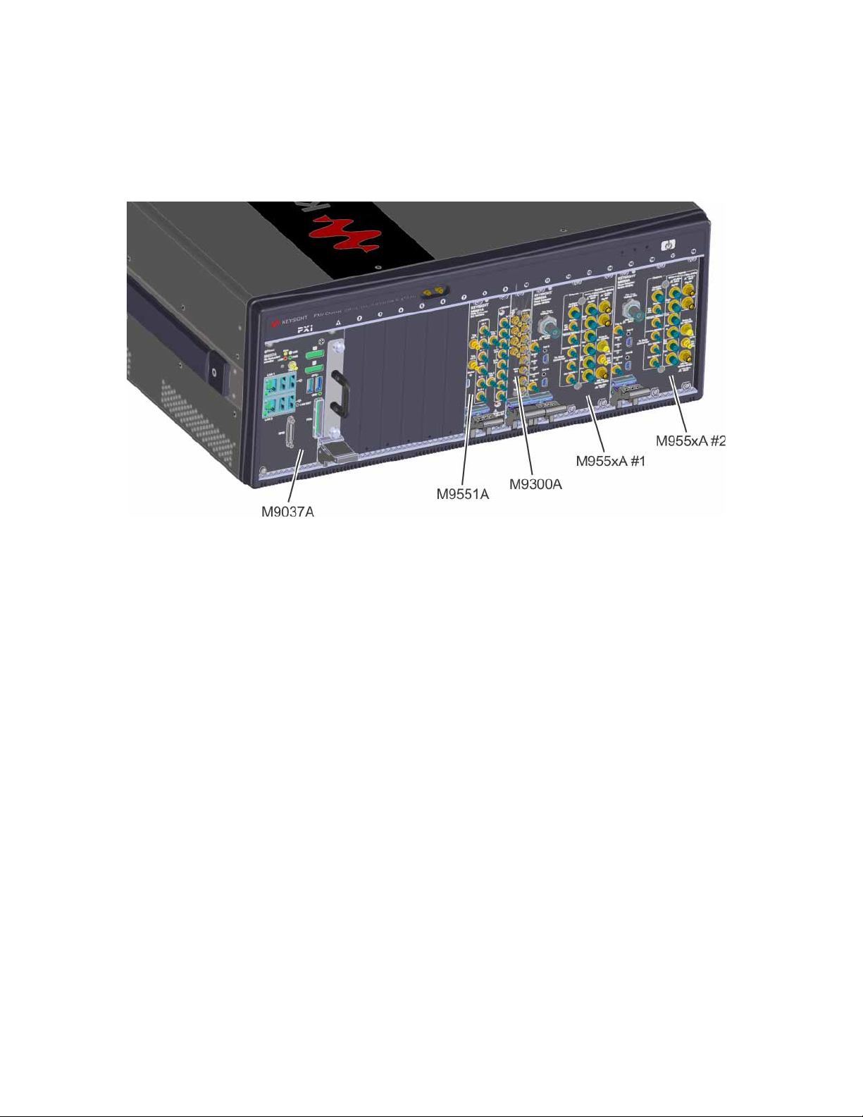
System Components
Figure 1-1 Keysight N5511A Phase Noise Test System
The N5511A system is available as a benchtop model. Due to the system’s
flexibility, the hardware in the system varies with the options selected. You may
be installing instruments you already own in the system as well. A typical
N5511A system includes these components:
— N5511A PXIe chassis
— M9037A Controller with removable SSD drive with Windows 10 Professional
— M9551A Data Converter
— M9300A Frequency Reference
— M9550A Phase Detector 1 or 2

N5511A Phase Noise Test System Getting Started Guide 13
Initial Setup
Making Connections
Making Connections
Use the information in this section to connect your system hardware.
1. Verify all cables connected to instruments with the appropriate
connectors and adapters, using the following pages in this section.
2. You may connect other assets (in addition to those supplied with the
system) either at this time or after running the confidence test.
3. Lastly, connect the power cord(s) to the AC power supply.
Before connecting the cables to any device:
— Check all connectors for wear or dirt.
— When making the connection, torque the connector to the proper value.
Proper Connector Torque
— Provides more accurate measurements
— Keeps moisture out of the connectors
— Eliminates radio frequency interference (RFI) from affecting your
measurements
The torque required depends on the type of connector. Refer to Table 1-3. Do
not overtighten the connector.
Never exceed the recommended torque when attaching cables.
Make all system hardware connections without AC power applied. Failure to do so may result in
damage to the hardware. Make connections in a properly grounded environment. Keysight
recommends wearing grounding wrist or foot straps. Failure to do so may result in damage to the
hardware.
Keysight Technologies recommends the use of adaptors as connector savers to extend the
lifespan of the test ports on the N5511A Phase Noise Test System.
USE CAUTION WHEN INSTALLING ADAPTORS! Rotation of the adaptor after the connectors are
engaged will damage the connector on the system.
Table 1-3 Proper Connector Torque
Connector Torque cm-kg Torque N-cm Torque in-lbs Wrench P/N
Type-N 52 508 45 hand tighten
3.5 mm 9.2 90 8 8710-1765
2.92 mm 9.2 90 8 8710-1765
14 N5511A Phase Noise Test System Getting Started Guide
Initial Setup
Making Connections
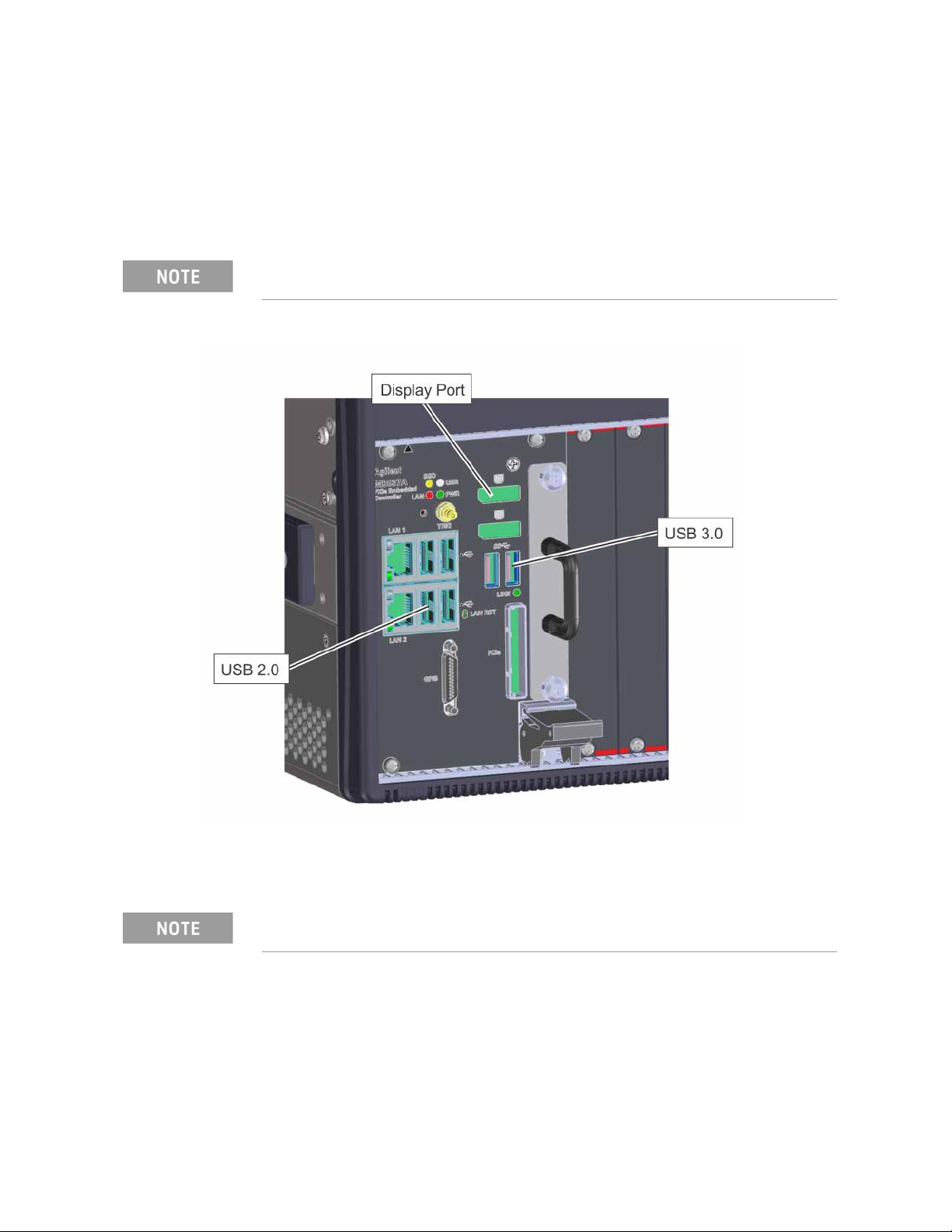
Connecting a Display to your System
The N5511A Phase noise test system does not have a display.
You will have to provide a monitor to view the user interface. Connect a display
port cable to the M9037A controller display port connection and your monitor.
Figure 1-2 M9037A Controller Display Port
Connect the keyboard and mouse to the USB 2.0 ports.
You can use an adapter for other monitor cable types to the display port.
Proper ergonomics should be considered when using accessories such as a keyboard or a mouse.
N5511A Phase Noise Test System Getting Started Guide 15
Initial Setup
Powering the System On
Powering the System On
Connect your system to an appropriate AC power source using the power cord
provided.
The N5511A system is shipped with an AC power cord appropriate for your
location.
The N5511A Benchtop system consists of an N5511A Phase Noise Test System
with one or two test sets installed. You must connect a monitor, keyboard, and
mouse before powering on the system.
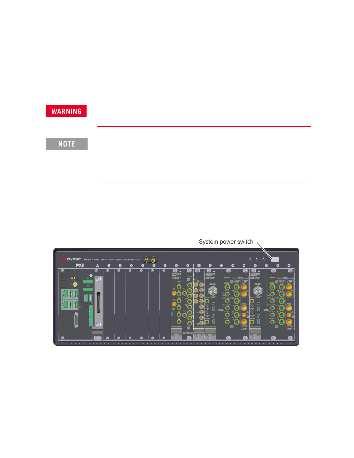
Press the system power switch.
Figure 1-3 Power on the N5511A System
To power on a racked system
1. Press the system power switch (front, top right of the rack) to the on
position.
2. Verify that all instrument power switches are on.
3. Allow the system to warm up for 30 minutes.
Before applying power, make sure the AC power input and the location of the system meet the
requirements given in Table 2-7 on page 34. Failure to do so may result in damage to the
system or personal injury.
Warm-up Time: The downconverter and RF source instruments contain ovenized oscillators
which must warm up for 30 minutes to produce accurate measurements.
Standby Mode: The RF source uses a standby mode to keep the ovenized oscillator warm when
the instrument is connected (plugged in) to AC power, even when the power switch is in the off
position. To completely shut down the instrument, you must disconnect it from the AC power
supply.
16 N5511A Phase Noise Test System Getting Started Guide
Initial Setup
Starting the Measurement Software
Starting the Measurement Software
The N5510 software is pre-installed on the N5511A Phase Noise system.
Choose the N5510 software icon to launch the user interface.
Figure 1-4 Splash Screen
Keysight Technologies, Inc. has not provided internet security software for this N5511A
Phase Noise Test System. Connecting the PC to a Local Area Network (LAN), without first
installing internet security software (firewall, virus protection, etc) puts both your PC and data at
risk. If you decide to connect the N5511A to a LAN, without first installing internet security
software, you do so at your own risk.
Keysight recommends turning on Windows updates and installing updates when available from
Microsoft.
During the first boot up of the system, you will see the Windows End-User License Agreement
screen. Click Agree to continue. If Disagree is selected, the system will shut down and the
same EULA will appear when the system is booted.

N5511A Phase Noise Test System Getting Started Guide 17
Initial Setup
Starting the Measurement Software
1. To start the program, double-click on the N5510 icon on the desktop
shortcut (shown above), or navigate to the N5510 User Interface through
the Windows start menu. Click Start > All Programs > Keysight N5510 >
N5510 User Interface.
2. When the program starts, the main N5510 measurement window appears
(see Figure 1-5). It shows the phase noise graph.
Figure 1-5 Main N5510 user interface window
18 N5511A Phase Noise Test System Getting Started Guide
Initial Setup
Starting the Measurement Software
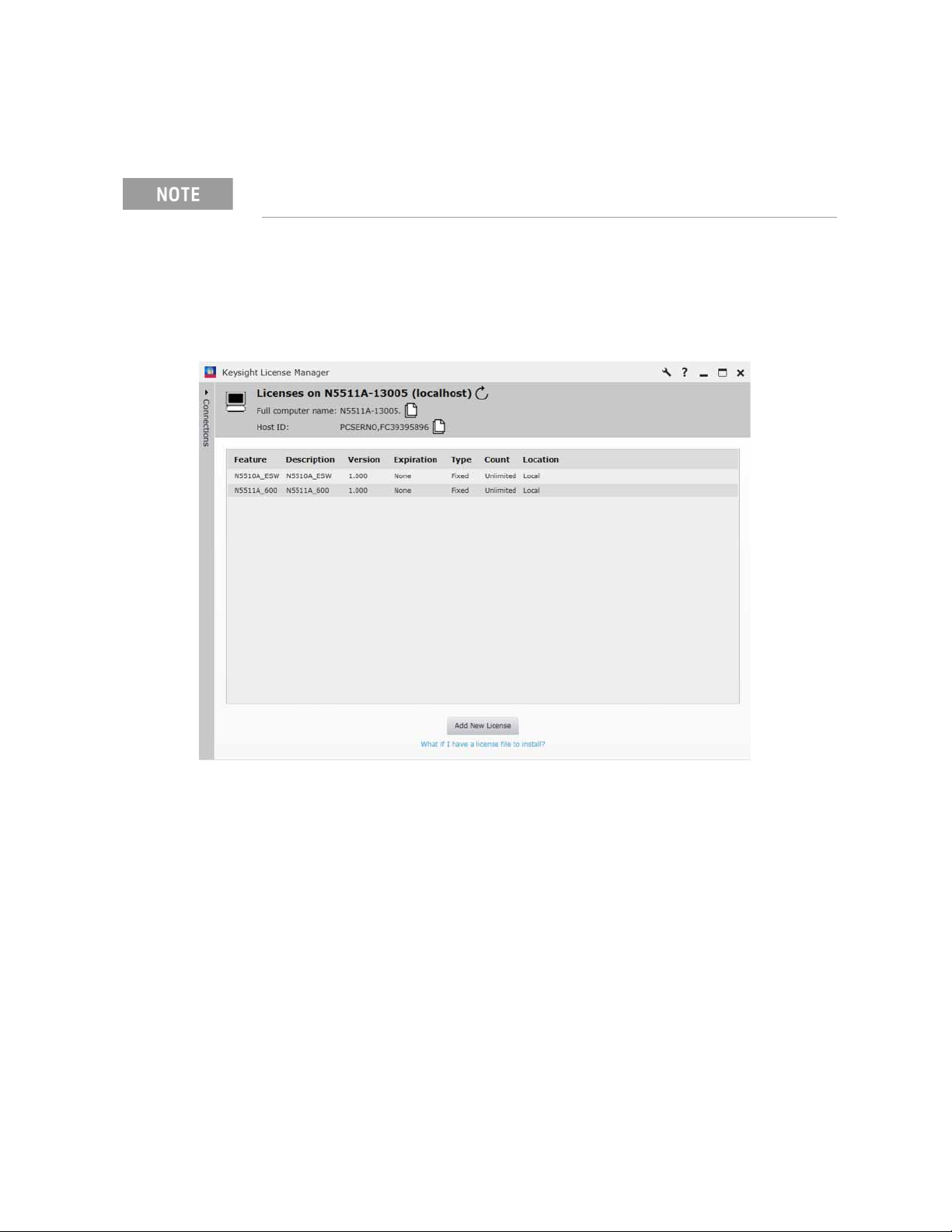
Verify License Key is Installed
3. Use the Keysight License Manager to see the license keys installed. Start
> All Programs > Keysight License Manager > Keysight License Manager
4. Verify the licenses are installed.
Figure 1-6 Keysight License Manager
The N5511A will have the license key already installed, but if you ever need to install the license
key, use the following procedure.
N5511A Phase Noise Test System Getting Started Guide 19
Initial Setup
Asset Manager
Asset Manager
The Asset Manager adds assets to the N5511A system. All the test sets and
digitizers should be installed at the factory. The procedure is essentially the
same for any asset. We use a source as an example. Adding an asset involves
two steps, once the hardware connections have been made:
— Configuring the asset
— Verifying the server hardware connections.
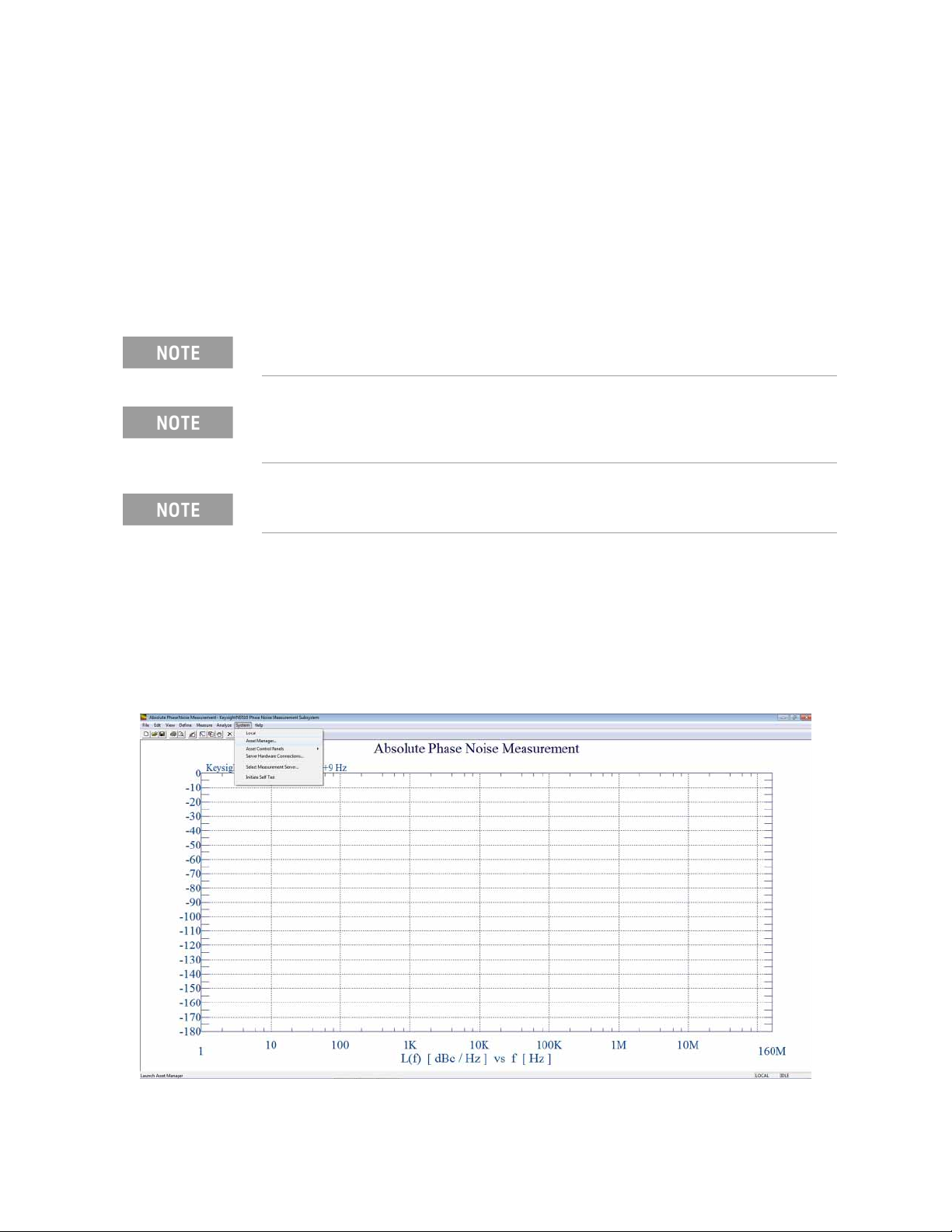
Configuring an Asset
1. Using Figure 1-7 as a guide, navigate to Asset Manager. For this example
we invoke the Asset Manager Wizard from the N5510 main screen. This is
the most common way to add assets.
Figure 1-7 Navigate to Asset Manager
Reloading or installing a software update will require re-installing all the assets.
If you have not already connected the assets to the system, do so now. Be sure to power off the
system before making all hardware connections other than LAN. (For more information on
connecting assets, see Chapter 3, “System Interconnections”)
Instruments that only have GPIB interface will use the 82357B USB to GPIB Interface Adapter.
20 N5511A Phase Noise Test System Getting Started Guide
Initial Setup
Asset Manager
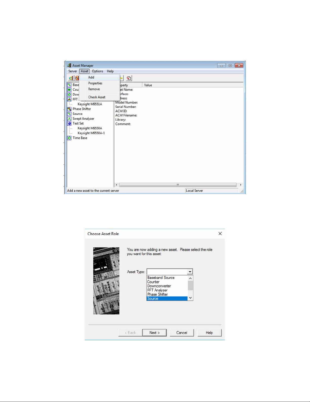
2. Refer to Figure 1-8. Select Add in the Asset Manager window.
Figure 1-8 Navigate to Add in Asset Manager
3. Refer to Figure 1-9. From the Asset Type pull-down list in Choose Asset
Role dialog box, select Source, then click Next.
Figure 1-9 Select source as asset type
Other manuals for N5511A
1
Table of contents
Other Keysight Technologies Recording Equipment manuals


