Keysight Technologies N5102A User manual

Installation Guide
Keysight N5102A Baseband Studio Digital Signal
Interface Module
Due to our continuing efforts to improve our products through firmware and hardware
revisions, N5102A module design and operation may vary from descriptions in this
guide. We recommend that you use the latest revision of this guide to ensure you have
up-to-date product information. Compare the print date of this guide with the latest
revision, which can be downloaded from the following website:
http://www.keysight.com/find/basebandstudio
Notice: This document contains references to Agilent.
Please note that Agilent’s Test and Measurement
business has become Keysight Technologies. For
more information, go to www.keysight.com.

Notices
© Keysight Technologies, Inc.
2012-2015
No part of this manual may be
reproduced in any form or by any
means (including electronic storage
and retrieval or translation into a
foreign language) without prior
agreement and written consent from
Keysight Technologies, Inc. as
governed by United States and
international copyright laws.
Trademark Acknowledgments
Manual Part Number
N5102-90003
Print Date
January 2015
Published in USA
Keysight Technologies
1400 Fountaingrove Parkway
Santa Rosa, CA 95403
Warranty
THE MATERIAL CONTAINED IN THIS
DOCUMENT IS PROVIDED “AS IS,”
AND IS SUBJECT TO BEING
CHANGED, WITHOUT NOTICE, IN
FUTURE EDITIONS. FURTHER, TO
THE MAXIMUM EXTENT PERMITTED
BY APPLICABLE LAW, KEYSIGHT
DISCLAIMS ALL WARRANTIES,
EITHER EXPRESS OR IMPLIED WITH
REGARD TO THIS MANUAL AND
ANY INFORMATION CONTAINED
HEREIN, INCLUDING BUT NOT
LIMITED TO THE IMPLIED
WARRANTIES OF
MERCHANTABILITY AND FITNESS
FOR A PARTICULAR PURPOSE.
KEYSIGHT SHALL NOT BE LIABLE
FOR ERRORS OR FOR INCIDENTAL
OR CONSEQUENTIAL DAMAGES IN
CONNECTION WITH THE
FURNISHING, USE, OR
PERFORMANCE OF THIS
DOCUMENT OR ANY INFORMATION
CONTAINED HEREIN. SHOULD
KEYSIGHT AND THE USER HAVE A
SEPARATE WRITTEN AGREEMENT
WITH WARRANTY TERMS
COVERING THE MATERIAL IN THIS
DOCUMENT THAT CONFLICT WITH
THESE TERMS, THE WARRANTY
TERMS IN THE SEPARATE
AGREEMENT WILL CONTROL.
Technology Licenses
The hardware and/or software
described in this document are
furnished under a license and may be
used or copied only in accordance
with the terms of such license.
Restricted Rights Legend
If software is for use in the
performance of a U.S. Government
prime contract or subcontract,
Software is delivered and licensed as
“Commercial computer software” as
defined in DFAR 252.227-7014 (June
1995), or as a “commercial item” as
defined in FAR 2.101(a) or as
“Restricted computer software” as
defined in FAR 52.227-19 (June
1987) or any equivalent agency
regulation or contract clause. Use,
duplication or disclosure of Software
is subject to Keysight Technologies’
standard commercial license terms,
and non-DOD Departments and
Agencies of the U.S. Government will
receive no greater than Restricted
Rights as defined in FAR
52.227-19(c)(1-2) (June 1987). U.S.
Government users will receive no
greater than Limited Rights as
defined in FAR 52.227-14 (June
1987) or DFAR 252.227-7015 (b)(2)
(November 1995), as applicable in
any technical data.
Safety Notices
CAUTION
A CAUTION notice denotes a hazard. It
calls attention to an operating
procedure, practice, or the like that,
if not correctly performed or adhered
to, could result in damage to the
product or loss of important data. Do
not proceed beyond a CAUTION
notice until the indicated conditions
are fully understood and met.
WARNING
A WARNING notice denotes a hazard.
It calls attention to an operating
procedure, practice, or the like that,
if not correctly performed or adhered
to, could result in personal injury or
death. Do not proceed beyond a
WARNING notice until the indicated
conditions are fully understood and
met.

iii
Where to Find the Latest Information
Documentation is updated periodically. For the latest information about these products, including instrument software
upgrades, application information, and product information, browse to one of the following URLs, according to the name
of your product:
http://www.keysight.com/find/basebandstudio
To receive the latest updates by email, subscribe to Keysight Email Updates at the following URL:
http://www.keysight.com/find/MyKeysight
Information on preventing analyzer damage can be found at:
www.keysight.com/find/PreventingInstrumentRepair
Is your product software up-to-date?
Periodically, Keysight releases software updates to fix known defects and incorporate product enhancements. To search
for software updates for your product, go to the Keysight Technical Support website at:
http://www.keysight.com/find/techsupport

iv

Contents
v
Table of Contents
1. Installation
Safety Information. . . . . . . . . . . . . . . . . . . . . . . . . . . . . . . . . . . . . . . . . . . . . . . . . . . . . . . . . . . . . . . . . . . . . . . . . . . . . 2
Warnings, Cautions, and Notes . . . . . . . . . . . . . . . . . . . . . . . . . . . . . . . . . . . . . . . . . . . . . . . . . . . . . . . . . . . . . . 2
Instrument Markings. . . . . . . . . . . . . . . . . . . . . . . . . . . . . . . . . . . . . . . . . . . . . . . . . . . . . . . . . . . . . . . . . . . . . . . 2
General Safety Considerations . . . . . . . . . . . . . . . . . . . . . . . . . . . . . . . . . . . . . . . . . . . . . . . . . . . . . . . . . . . . . . . 3
Getting Started . . . . . . . . . . . . . . . . . . . . . . . . . . . . . . . . . . . . . . . . . . . . . . . . . . . . . . . . . . . . . . . . . . . . . . . . . . . . . . . 4
Checking the Shipment. . . . . . . . . . . . . . . . . . . . . . . . . . . . . . . . . . . . . . . . . . . . . . . . . . . . . . . . . . . . . . . . . . . . . 4
Meeting Electrical and Environmental Requirements . . . . . . . . . . . . . . . . . . . . . . . . . . . . . . . . . . . . . . . . . . . . . 4
Ventilation . . . . . . . . . . . . . . . . . . . . . . . . . . . . . . . . . . . . . . . . . . . . . . . . . . . . . . . . . . . . . . . . . . . . . . . . . . . . . . . 5
Line Settings . . . . . . . . . . . . . . . . . . . . . . . . . . . . . . . . . . . . . . . . . . . . . . . . . . . . . . . . . . . . . . . . . . . . . . . . . . . . . 5
Connecting the AC Power Cord . . . . . . . . . . . . . . . . . . . . . . . . . . . . . . . . . . . . . . . . . . . . . . . . . . . . . . . . . . . . . . 6
AC Power Cord Localization . . . . . . . . . . . . . . . . . . . . . . . . . . . . . . . . . . . . . . . . . . . . . . . . . . . . . . . . . . . . . . . . . 6
Proper Usage and Cleaning . . . . . . . . . . . . . . . . . . . . . . . . . . . . . . . . . . . . . . . . . . . . . . . . . . . . . . . . . . . . . . . . . 6
Connecting the N5102A Module to the ESG/PSG/X-Series (N5182B/72B) or N5101A PCI Card. . . . . . . . . . . . . . . 8
Operation Verification. . . . . . . . . . . . . . . . . . . . . . . . . . . . . . . . . . . . . . . . . . . . . . . . . . . . . . . . . . . . . . . . . . . . . . . . . 11
Regulatory Information. . . . . . . . . . . . . . . . . . . . . . . . . . . . . . . . . . . . . . . . . . . . . . . . . . . . . . . . . . . . . . . . . . . . . . . . 13
Statement of Compliance . . . . . . . . . . . . . . . . . . . . . . . . . . . . . . . . . . . . . . . . . . . . . . . . . . . . . . . . . . . . . . . . . . 13
Assistance . . . . . . . . . . . . . . . . . . . . . . . . . . . . . . . . . . . . . . . . . . . . . . . . . . . . . . . . . . . . . . . . . . . . . . . . . . . . . . 13
Certification. . . . . . . . . . . . . . . . . . . . . . . . . . . . . . . . . . . . . . . . . . . . . . . . . . . . . . . . . . . . . . . . . . . . . . . . . . . . . 13
Declaration of Conformity. . . . . . . . . . . . . . . . . . . . . . . . . . . . . . . . . . . . . . . . . . . . . . . . . . . . . . . . . . . . . . . . . . 13
Compliance with German Noise Requirements . . . . . . . . . . . . . . . . . . . . . . . . . . . . . . . . . . . . . . . . . . . . . . . . . 13
Compliance with Canadian EMC Requirements. . . . . . . . . . . . . . . . . . . . . . . . . . . . . . . . . . . . . . . . . . . . . . . . . 13
2. Overview
Features. . . . . . . . . . . . . . . . . . . . . . . . . . . . . . . . . . . . . . . . . . . . . . . . . . . . . . . . . . . . . . . . . . . . . . . . . . . . . . . . . . . . 16
Front Panel . . . . . . . . . . . . . . . . . . . . . . . . . . . . . . . . . . . . . . . . . . . . . . . . . . . . . . . . . . . . . . . . . . . . . . . . . . . . . . . . . 19
1. DC Power Receptacle . . . . . . . . . . . . . . . . . . . . . . . . . . . . . . . . . . . . . . . . . . . . . . . . . . . . . . . . . . . . . . . . . . . 19
2. Power LED. . . . . . . . . . . . . . . . . . . . . . . . . . . . . . . . . . . . . . . . . . . . . . . . . . . . . . . . . . . . . . . . . . . . . . . . . . . . 19
3. Status LED. . . . . . . . . . . . . . . . . . . . . . . . . . . . . . . . . . . . . . . . . . . . . . . . . . . . . . . . . . . . . . . . . . . . . . . . . . . . 19
4. Digital Bus Connector. . . . . . . . . . . . . . . . . . . . . . . . . . . . . . . . . . . . . . . . . . . . . . . . . . . . . . . . . . . . . . . . . . . 20
5. Freq Ref Connector. . . . . . . . . . . . . . . . . . . . . . . . . . . . . . . . . . . . . . . . . . . . . . . . . . . . . . . . . . . . . . . . . . . . . 20
Rear Panel. . . . . . . . . . . . . . . . . . . . . . . . . . . . . . . . . . . . . . . . . . . . . . . . . . . . . . . . . . . . . . . . . . . . . . . . . . . . . . . . . . 21
1. Ext Clock In Connector . . . . . . . . . . . . . . . . . . . . . . . . . . . . . . . . . . . . . . . . . . . . . . . . . . . . . . . . . . . . . . . . . . 22
2. Clock Out Connector. . . . . . . . . . . . . . . . . . . . . . . . . . . . . . . . . . . . . . . . . . . . . . . . . . . . . . . . . . . . . . . . . . . . 22
3. Device Interface Connector . . . . . . . . . . . . . . . . . . . . . . . . . . . . . . . . . . . . . . . . . . . . . . . . . . . . . . . . . . . . . . 22
3. Device Interface Connections
Break-Out Boards . . . . . . . . . . . . . . . . . . . . . . . . . . . . . . . . . . . . . . . . . . . . . . . . . . . . . . . . . . . . . . . . . . . . . . . . . . . . 24
Dual 20-Pin Break-Out Board. . . . . . . . . . . . . . . . . . . . . . . . . . . . . . . . . . . . . . . . . . . . . . . . . . . . . . . . . . . . . . . 25
Dual 38-Pin Break-Out Board. . . . . . . . . . . . . . . . . . . . . . . . . . . . . . . . . . . . . . . . . . . . . . . . . . . . . . . . . . . . . . . 27
Dual 40 Pin Break-Out Board . . . . . . . . . . . . . . . . . . . . . . . . . . . . . . . . . . . . . . . . . . . . . . . . . . . . . . . . . . . . . . . 29
Single 68-Pin SCSI Style Break-Out Board . . . . . . . . . . . . . . . . . . . . . . . . . . . . . . . . . . . . . . . . . . . . . . . . . . . . 30
Dual 100-Pin Break-Out Board. . . . . . . . . . . . . . . . . . . . . . . . . . . . . . . . . . . . . . . . . . . . . . . . . . . . . . . . . . . . . . 31
Device Interface Connector . . . . . . . . . . . . . . . . . . . . . . . . . . . . . . . . . . . . . . . . . . . . . . . . . . . . . . . . . . . . . . . . . . . . 33

vi
Contents
Input and Output Clock Signals . . . . . . . . . . . . . . . . . . . . . . . . . . . . . . . . . . . . . . . . . . . . . . . . . . . . . . . . . . . . . 36
Data Lines . . . . . . . . . . . . . . . . . . . . . . . . . . . . . . . . . . . . . . . . . . . . . . . . . . . . . . . . . . . . . . . . . . . . . . . . . . . . . . 36
DC Supply . . . . . . . . . . . . . . . . . . . . . . . . . . . . . . . . . . . . . . . . . . . . . . . . . . . . . . . . . . . . . . . . . . . . . . . . . . . . . . 37
VCCIO . . . . . . . . . . . . . . . . . . . . . . . . . . . . . . . . . . . . . . . . . . . . . . . . . . . . . . . . . . . . . . . . . . . . . . . . . . . . . . . . . 37
Device Interface Mating Connector . . . . . . . . . . . . . . . . . . . . . . . . . . . . . . . . . . . . . . . . . . . . . . . . . . . . . . . . . . . . . . 38
4. Troubleshooting
If You Encounter a Problem . . . . . . . . . . . . . . . . . . . . . . . . . . . . . . . . . . . . . . . . . . . . . . . . . . . . . . . . . . . . . . . . . . . . 42
Checking Power Problems . . . . . . . . . . . . . . . . . . . . . . . . . . . . . . . . . . . . . . . . . . . . . . . . . . . . . . . . . . . . . . . . . 43
Running Diagnostic Tests. . . . . . . . . . . . . . . . . . . . . . . . . . . . . . . . . . . . . . . . . . . . . . . . . . . . . . . . . . . . . . . . . . 44
Replaceable Parts. . . . . . . . . . . . . . . . . . . . . . . . . . . . . . . . . . . . . . . . . . . . . . . . . . . . . . . . . . . . . . . . . . . . . . . . . . . . 48
Returning an N5102A Module to Keysight Technologies . . . . . . . . . . . . . . . . . . . . . . . . . . . . . . . . . . . . . . . . . . . . . 49
Contacting Keysight Technologies. . . . . . . . . . . . . . . . . . . . . . . . . . . . . . . . . . . . . . . . . . . . . . . . . . . . . . . . . . . . . . . 50

1
Keysight Baseband Studio Digital Signal Interface Module
N5102A
Installation Guide
1 Installation
This chapter provides the following:
—“Safety Information” on page 2
—“Getting Started” on page 4
—“Connecting the N5102A Module to the ESG/PSG/X-Series (N5182B/72B)
or N5101A PCI Card” on page 8
—“Operation Verification” on page 11
—“Regulatory Information” on page 13

2
Installation
Safety Information
Safety Information
Warnings, Cautions, and Notes
The following safety notations are used throughout this manual. Familiarize
yourself with each notation and its meaning before operating this product.
WARNING Warning denotes a hazard. It calls attention to a condition or situation
that could result in personal injury or loss of life. Do not proceed
beyond a warning until the indicated conditions or situations are fully
understood.
CAUTION Caution calls attention to a possible condition or situation that could result in
a loss of a user’s work, damage, or destruction of the product. Do not proceed
beyond a caution until the indicated conditions are fully understood.
NOTE Note calls the user’s attention to an important point of special information
within the text. It provides operational information or additional instructions
of which the user should be aware.
Instrument Markings
The following markings are is used on the N5102A Baseband Studio digital
signal interface module. Familiarize yourself with it and its meaning before
operating the module.
The CE mark is a registered trademark of the European Community. If this symbol is
accompanied by a year, it is the year when the design was proven.
The CSA mark is a registered trademark of the Canadian Standards Association.
The C-Tick Mark is a trademark registered to the Australian Spectrum Management Agency.
This indicates compliance with all Australian EMC regulatory information.
This symbol indicates that the center conductor (of the power supply) is positive, and the
outer conductor is negative.
+
−

3
Installation
Safety Information
General Safety Considerations
WARNING Personal injury may result if the module cover is removed. There are no
operator serviceable parts inside. To avoid electrical shock, refer
servicing to qualified personnel.
This symbol indicates that the input power required is DC.
This symbol indicates compliance with the Canadian Interference-Causing Equipment
Standard (ICES-001).

4
Installation
Getting Started
Getting Started
Checking the Shipment
1. Inspect the shipping container for damage.
Signs of damage may include a dented or torn shipping container or
cushioning material that indicates signs of unusual stress or compacting.
2. Carefully remove the contents from the shipping container and verify that
your order is complete.
The following items are shipped standard with each N5102A Baseband
Studio digital signal interface module:
—installation guide
—three-prong AC power cord (specific to geographic location)
—power supply
—proprietary three-meter digital bus cable
—five break-out boards (PC boards with connectors that simplify the
connections between the N5102A module and the device under
test)
—loop back fixture (for troubleshooting)
—Device Interface port mating connector
See “Rear Panel” on page 21 for connector locations.
Instrument Dimensions
Length: 189.9 mm (7.48 in)
Width: 144.8 mm (5.70 in)
Height: 41.6 mm (1.64 in)
Meeting Electrical and Environmental Requirements
The N5102A module is designed for use in the following environmental
conditions:
— indoor use
— altitudes < 15,000 feet (4,572 meters)
— 0 to 55°C temperatures, unless otherwise specified
— 80% relative humidity (maximum for temperatures up to 31°C, decreasing
linearly to 50% relative humidity at 40°C).

5
Installation
Getting Started
CAUTION This product is designed for use in INSTALLATION CATEGORY II and
POLLUTION DEGREE 2, per IEC 61010-1 and 664, respectively.
Ventilation
Ventilation holes are located on the front and rear panels of the N5102A
module. Do not allow these holes to be obstructed, as they allow air flow
through the module.
When installing the module in a cabinet, the convection into and out of the
module must not be restricted. The ambient temperature outside the cabinet
must be less than the maximum operating temperature of the module by 4°C
for every 100 watts dissipated within the cabinet.
CAUTION Damage to the module may result when the total power dissipated in the
cabinet is greater than 800 watts. When this condition exists, forced
convection must be applied.
Line Settings
The N5102A module requires a power supply that meets the following
conditions:
Voltage: 5V
Frequency: DC
Current: 4.0A
The module’s power supply requires a power source that meets the following
conditions:
Voltage: 100-240V
Frequency: 50-60 Hz
Current: 0.7A
CAUTION Damage may result if a supply voltage is not within its specified range.

6
Installation
Getting Started
Connecting the AC Power Cord
This is a Safety Class 1 Product provided with a protective earth ground
incorporated into the power cord. The AC power cord is the device that
disconnects the mains circuits from the mains supply. In addition, an external
circuit breaker, readily identifiable and easily reached by the operator, should
be available for use as the disconnecting device. Use the following steps to
connect the AC power cord:
WARNING Personal injury may occur if there is any interruption of the protective
conductor inside or outside of the product. Intentional interruption is
prohibited.
CAUTION Damage to the product may result without adequate earth grounding.
Always use the supplied three-prong AC power cord.
1. Ensure that the power cord is not damaged.
2. Install the product so that one of the following items is readily identifiable
and easily reached by the operator: AC power cord, alternative switch, or
circuit breaker.
3. Insert the mains plug into a socket outlet provided with a protective earth
grounding.
AC Power Cord Localization
The AC power cord included with the module is appropriate for the final
shipping destination. You can, however, order additional AC power cords for
use in different areas: see “Replaceable Parts” on page 48.
Proper Usage and Cleaning
The N5102A module cover protects against physical contact with internal
assemblies that contain hazardous voltages, but does not protect against the
entrance of water. To avoid damage and personal injury, ensure that liquid
substances are positioned away from your N5102A module.
WARNING Personal injury may result if the N5102A module is not used as
specified. Unspecified use impairs the protection provided by the
equipment. The N5102A module must be used with all means for
protection intact.

7
Installation
Getting Started
Cleaning Suggestions
To prevent dust build-up that could potentially obstruct ventilation, clean the
N5102A module cover periodically. Use a dry cloth, or one slightly dampened
with water, to clean the external case parts.
WARNING To prevent electrical shock, disconnect the N5102A module from the
mains supply before cleaning. Do not attempt to clean internally.
8
Installation
Connecting the N5102A Module to the ESG/PSG/X-Series (N5182B/72B) or N5101A
PCI Card
Connecting the N5102A Module to the ESG/PSG/X-Series
(N5182B/72B) or N5101A PCI Card
The N5102A digital signal interface module is used with an Keysight E4438C
ESG1, E8267C PSG1, E8267D PSG1, X-Series (N5182B/72B), or a PC with an
installed Keysight N5101A PCI card being used with software2engineered to
control the N5102A module.
This section provides information on connecting the N5102A module to a
signal generator or N5101A PCI card. The illustrations in this procedure show
the N5102A module being connected to an ESG signal generator, however, the
connection process is the same for a PSG signal generator or a PCI card
installed in a PC. For more information on the N5101A PCI card, see the
N5101A Installation Guide.
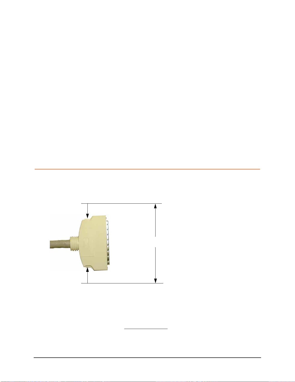
CAUTION The digital bus cable connector has a release latch on each side (as shown
below). To avoid connector damage, simultaneously squeeze both release
latches when connecting or disconnecting the cable. A securely connected
cable does not come loose when gently pulled.
1. Refer to Figure 1-1. Connect the end of the digital bus cable that has the
EMI suppressor to the signal generator or PCI card’s digital bus connector.
1. Requires Options 003 and/or 004, and either 601(if available) or 602.
2. For example, the N5110B Baseband Studio for waveform capture and playback software
is designed to control the N5102A module.
Digital bus cable connector release latches
Press release latches when connecting or disconnecting the cable.

9
Installation
Connecting the N5102A Module to the ESG/PSG/X-Series (N5182B/72B) or N5101A
PCI Card
NOTE The digital bus connector may be labeled as DIGITAL BUS, DIG I/Q I/O, or
DIGITAL I-Q I/O.
Figure 1-1 Signal Generator Digital Bus Cable Connection
2. Refer to Figure 1-2. Connect the other end of the digital bus cable to the
Digital Bus connector on the N5102A module.
The proprietary three meter cable enables you to place the interface
module in a location close to the device under test (DUT).
Figure 1-2 N5102A Module Digital Bus Cable Connection
3. Refer to Figure 1-3. Connect the AC power cord to both the power supply
and the AC power source (for details on connecting an AC power cord to
an AC power source, see “Connecting the AC Power Cord” on page 6).
4. Connect the power supply to the N5102A module DC power receptacle.
EMI Suppressor
Attach this end of the cable to the signal
generator or to the PCI card.
Press the release latches when connecting or disconnecting the cable.
Press the release latches when connecting or disconnecting the cable.
Press the release latches
when connecting or
disconnecting the cable.

10
Installation
Connecting the N5102A Module to the ESG/PSG/X-Series (N5182B/72B) or N5101A
PCI Card
Figure 1-3 N5102A Module Power Supply Connections
The power LED should be illuminated, indicating that the interface module is
connected to the power source. If the power LED is not illuminated, check the
AC power connection for the power supply and ensure that the DC power
supply plug is fully inserted into the N5102A module DC power receptacle. If
problems still persist after checking the power cords, refer to Chapter 4,
“Troubleshooting”, on page 41.
Figure 1-4 shows a completed installation.
Figure 1-4 Completed N5102A Module Installation
DC Power ConnectionAC Power Connection
Power LED is illuminated Note:
This illustration shows the N5102A module
connected to an ESG signal generator.
or an N5101A PCI card are similar.
Connections to a PSG signal generator

11
Installation
Operation Verification
Operation Verification
This section describes how to verify the operation of the N5102A module when
connected to an ESG or PSG signal generator. The operation verification uses
the device interface test (Device Intfc), which is one of four interface module
diagnostic tests, referred to as loop back tests. This loop back test checks the
complete setup, providing a high level of confidence that the system is
functioning properly. The three other tests are used if this test fails, and are
described in “Running Diagnostic Tests” on page 44.
If your N5102A interface module is connected to an N5101A PCI card in a PC,
operation verification occurs through the controlling software (for example,
N5110B Baseband Studio for waveform capture and playback). For more
information, see the software’s documentation.
CAUTION The Device Interface connector on the interface module communicates using
high speed digital data. Use ESD precautions to eliminate potential damage
when making connections.
1. Connect the N5102A module to the signal generator (as described in
“Connecting the N5102A Module to the ESG/PSG/X-Series (N5182B/72B)
or N5101A PCI Card” on page 8).
2. Refer to Figure 1-5. Connect the Loop Back Test Single Ended IO Dual 40
Pin board to the Device Interface connector on the rear panel of the
N5102A module.
Figure 1-5 Connecting the Loop Back Board to the N5102A Module
The Loop Back Test Single Ended IO Dual 40 Pin board is used both for
loop back testing and as a break-out board to simplify the connection
between the N5102A module and the device under test. When used for
loopback testing, there should be no connections to the dual 40-pin
connectors.
3. If the signal generator is not already on, turn it on.
Loop Back Test Single Ended IO Dual 40 Pin Board Connecting the Board to the Device Interface Connector

12
Installation
Operation Verification
4. On the signal generator, select the device interface test:
Press Aux Fctn > N5102A Interface > Diagnostics > Loop Back Test Type >
Device Intfc.
As shown in Figure 1-6, the currently selected test is displayed in
parenthesis below the
Loop Back Test Type softkey. Note also that the graphic provided displays
the current test setup.
Figure 1-6 ESG/PSG/X-Series (N5182B/72B) Diagnostic Test Display
5. Run the selected test: press Run Loop Back Test.
When the test completes, the results of the test (pass or fail) replaces
Unknown in both the parenthesis with the softkey and in the Status
Summary display as shown in Figure 1-7. If this test fails, refer to “Running
Diagnostic Tests” on page 44.
Figure 1-7 ESG/PSG/X-Series (N5182B/72B) Loop Back Test Result
Selected loop back test
Loop back test setup
Loop back test results

13
Installation
Regulatory Information
Regulatory Information
Statement of Compliance
This product has been designed and tested in accordance with IEC Publication
61010, Safety Requirements for Electronic Measuring Apparatus, and has
been supplied in a safe condition. The documentation contains information and
warnings that must be followed by the user to ensure safe operation and to
maintain the product in a safe condition.
Assistance
Product maintenance agreements and other customer assistance agreements
are available for Keysight Technologies products. For any assistance, contact
Keysight Technologies (see page 49).
Certification
Keysight Technologies certifies that this product met its published
specifications at the time of shipment from the factory.
This product does not require calibration.
Declaration of Conformity
A declaration of conformity is on file for this product, and a copy is available
upon request.
Compliance with German Noise Requirements
This is to declare that this instrument is in conformance with the German
Regulation on Noise Declaration for Machines (Laermangabe nach der
Maschinenlaermrerordnung
-3.GSGV Deutschland).
Compliance with Canadian EMC Requirements
This ISM device complies with Canadian ICES-001.
Cet appareil ISM est conforme a la norme NMB du Canada.
Table 1-1 German Noise Requirements
Acoustic Noise Emission/Geraeuschemission
LpA < 70 dB LpA < 70 dB
Operator position am Arbeitsplatz
Normal position normaler Betrieb
per ISO 7779 nach DIN 45635 t.19

14
Installation
Regulatory Information
Table of contents
Other Keysight Technologies Recording Equipment manuals


