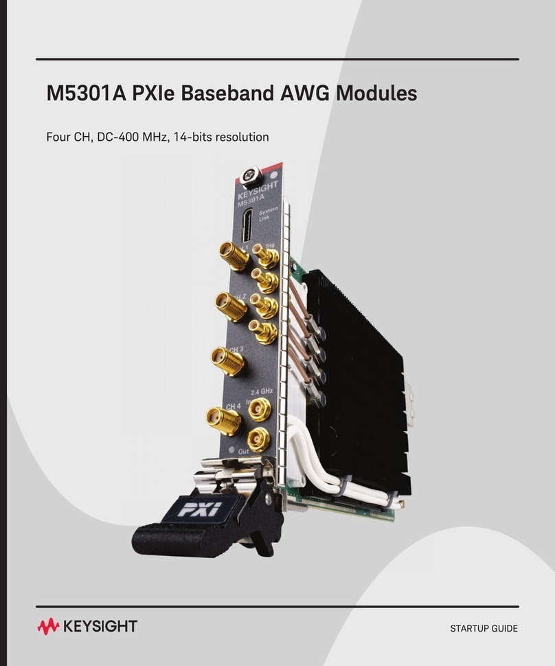
Keysight M9022A User manual

Keysight PXIe System Modules
M9022A, M9023A, M9024A, M9025A
INSTALLATION GUIDE


Notices
© Keysight Technologies, Inc. 2015-2022
No part of this manual may be repro-
duced in any form or by any means
(including electronic storage and retrieval
or translation into a foreign language)
without prior agreement and written con-
sent from Keysight Technologies, Inc. as
governed by United States and interna-
tional copyright laws.
Manual Part Number
M9022-90001
Edition
Seventh Edition, November 2022
Printed in
Malaysia
Published by
Keysight Technologies, Inc.
900 S. Taft Ave.
Loveland, CO 80537 USA
Trademarks
PICMG®, CompactPCI® are registered
trademarks of the PCI Industrial Com-
puter Manufacturers Group.
AdvancedTCA® and ATCA are registered
trademarks of the PCI Industrial Com-
puter Manufacturers Group.
PCI-SIG®, PCI Express®, and PCIe® are
registered trademarks of PCI-SIG.
Technology Licenses
The hardware and/or software described
in this document are furnished under a
license and may be used or copied only in
accordance with the terms of such
license.
Declaration of Conformity
Declarations of Conformity for this prod-
uct and for other Keysight products may
be downloaded from the Web. Go to
http://keysight.com/go/conformity.
You can then search by product number
to find the latest Declaration of Confor-
mity.
U.S. Government Rights
The Software is “commercial computer
software,” as defined by Federal Acquisi-
tion Regulation (“FAR”) 2.101. Pursuant
to FAR 12.212 and 27.405-3 and Depart-
ment of Defense FAR Supplement
(“DFARS”) 227.7202, the U.S. govern-
ment acquires commercial computer
software under the same terms by which
the software is customarily provided to
the public. Accordingly, Keysight pro-
vides the Software to U.S. government
customers under its standard commercial
license, which is embodied in its End
User License Agreement (EULA), a copy
of which can be found at http://
www.keysight.com/find/sweula. The
license set forth in the EULA represents
the exclusive authority by which the U.S.
government may use, modify, distribute,
or disclose the Software. The EULA and
the license set forth therein, does not
require or permit, among other things,
that Keysight: (1) Furnish technical infor-
mation related to commercial computer
software or commercial computer soft-
ware documentation that is not custom-
arily provided to the public; or (2)
Relinquish to, or otherwise provide, the
government rights in excess of these
rights customarily provided to the public
to use, modify, reproduce, release, per-
form, display, or disclose commercial
computer software or commercial com-
puter software documentation. No addi-
tional government requirements beyond
those set forth in the EULA shall apply,
except to the extent that those terms,
rights, or licenses are explicitly required
from all providers of commercial com-
puter software pursuant to the FAR and
the DFARS and are set forth specifically
in writing elsewhere in the EULA. Key-
sight shall be under no obligation to
update, revise or otherwise modify the
Software. With respect to any technical
data as defined by FAR 2.101, pursuant
to FAR 12.211 and 27.404.2 and DFARS
227.7102, the U.S. government acquires
no greater than Limited Rights as defined
in FAR 27.401 or DFAR 227.7103-5 (c), as
applicable in any technical data.
Warranty
THE MATERIAL CONTAINED IN THIS
DOCUMENT IS PROVIDED “AS IS,” AND
IS SUBJECT TO BEING CHANGED,
WITHOUT NOTICE, IN FUTURE EDI-
TIONS. FURTHER, TO THE MAXIMUM
EXTENT PERMITTED BY APPLICABLE
LAW, KEYSIGHT DISCLAIMS ALL WAR-
RANTIES, EITHER EXPRESS OR IMPLIED,
WITH REGARD TO THIS MANUAL AND
ANY INFORMATION CONTAINED
HEREIN, INCLUDING BUT NOT LIMITED
TO THE IMPLIED WARRANTIES OF MER-
CHANTABILITY AND FITNESS FOR A
PARTICULAR PURPOSE. KEYSIGHT
SHALL NOT BE LIABLE FOR ERRORS OR
FOR INCIDENTAL OR CONSEQUENTIAL
DAMAGES IN CONNECTION WITH THE
FURNISHING, USE, OR PERFORMANCE
OF THIS DOCUMENT OR OF ANY INFOR-
MATION CONTAINED HEREIN. SHOULD
KEYSIGHT AND THE USER HAVE A SEP-
ARATE WRITTEN AGREEMENT WITH
WARRANTY TERMS COVERING THE
MATERIAL IN THIS DOCUMENT THAT
CONFLICT WITH THESE TERMS, THE
WARRANTY TERMS IN THE SEPARATE
AGREEMENT SHALL CONTROL.
Keysight Technologies does not warrant
third-party system-level (combination of
chassis, controllers, modules, etc.) per-
formance, safety, or regulatory compli-
ance unless specifically stated.
Safety Information
A CAUTION denotes a hazard. It calls
attention to an operating procedure
or practice that, if not correctly per-
formed or adhered to, could result in
damage to the product or loss of
important data. Do not proceed
beyond a CAUTION notice until the
indicated conditions are fully under-
stood and met.
A WARNING denotes a hazard. It
calls attention to an operating pro-
cedure or practice, that, if not cor-
rectly performed or adhered to,
could result in personal injury or
death. Do not proceed beyond a
WARNING notice until the indicated
conditions are fully understood and
met.

iviv
Safety Information
The following general safety precau-
tions must be observed during all
phases of operation of this instrument.
Failure to comply with these precau-
tions or with specific warnings or oper-
ating instructions in the product
manuals violates safety standards of
design, manufacture, and intended use
of the instrument. Keysight Technolo-
gies assumes no liability for the cus-
tomer's failure to comply with these
requirements.
General
Do not use this product in any manner not
specified by the manufacturer. The protec-
tive features of this product must not be
impaired if it is used in a manner specified in
the operation instructions.
Before Applying Power
Verify that all safety precautions are taken.
Make all connections to the unit before
applying power. Note the external markings
described under “Safety Symbols”.
Ground the Instrument
Keysight chassis are provided with a
grounding-type power plug. The
instrument chassis and cover must be
connected to an electrical ground to
minimize shock hazard. The ground pin
must be firmly connected to an electri-
cal ground (safety ground) terminal at
the power outlet. Any interruption of
the protective (grounding) conductor
or disconnection of the protective
earth terminal will cause a potential
shock hazard that could result in per-
sonal injury.
Do Not Operate in an Explosive
Atmosphere
Do not operate the module/chassis in
the presence of flammable gases or
fumes.
Do Not Operate Near Flammable
Liquids
Do not operate the module/chassis in
the presence of flammable liquids or
near containers of such liquids.
Cleaning
Clean the outside of the Keysight mod-
ule/chassis with a soft, lint-free,
slightly dampened cloth. Do not use
detergent or chemical solvents. To
prevent electrical shock, disconnect
the instrument from mains before
cleaning. Use a dry cloth or one sightly
dampened with water to clean the
external case parts. Do not attempt to
clean internally.
Do Not Remove Instrument Cover
Only qualified, service-trained person-
nel who are aware of the hazards
involved should remove instrument
covers. Always disconnect the power
cable and any external circuits before
removing the instrument cover.
Keep Away From Live Circuits
Operating personnel must not remove
equipment covers or shields. Proce-
dures involving the removal of covers
and shields are for use by service-
trained personnel only. Under certain
conditions, dangerous voltages may
exist even with the equipment
switched off. To avoid dangerous elec-
trical shock, DO NOT perform proce-
dures involving cover or shield
removal unless you are qualified to do
so.
Do Not Operate Damaged
Equipment
Whenever it is possible that the safety
protection features built into this
prod-uct have been impaired, either
through physical damage, excessive
moisture, or any other reason,
REMOVE POWER and do not use the
product until safe operation can be
verified by service-trained personnel.
If necessary, return the product to an
Keysight Technolo-gies Sales and
Service Office for ser-vice and repair
to ensure the safety features are
maintained.
Do Not Block The Primary
Disconnect
The primary disconnect device is the
appliance connector/power cord when
a chassis used by itself, but when
installed into a rack or system the dis-
connect may be impaired and must be
considered part of the installation.
Do Not Modify the Instrument
Do not install substitute parts or per-
form any unauthorized modification to
the product. Return the product to an
Keysight Sales and Service Office to
ensure that safety features are main-
tained.
In Case of Damage
Instruments that appear damaged or
defective should be made inoperative
and secured against unintended oper-
ation until they can be repaired by
qualified service personnel.
Do NOT block vents and fan exhaust:
To ensure adequate cooling and venti-
lation, leave a gap of at least 50mm
(2") around vent holes on both sides of
the chassis.
Do NOT operate with empty slots: To
ensure proper cooling and avoid dam-
aging equipment, fill each empty slot
with an PXIe filler panel module.
Do NOT stack free-standing chassis:
Stacked chassis should be rack-
mounted.
All modules are grounded through the
chassis: During installation, tighten
each module's retaining screws to
secure the module to the chassis and
to make the ground connection.
Operator is responsible to maintain
safe operating conditions. To ensure
safe operating conditions, modules
should not be operated beyond the full
temperature range specified in the
Environmental and physical specifica-
tion. Exceeding safe operating condi-
tions can result in shorter lifespan,
improper module performance and
user safety issues. When the modules
are in use and operation within the
specified full temperature range is not
maintained, module surface tempera-
tures may exceed safe handling condi-
tions which can cause discomfort or
burns if touched. In the event of a
module exceeding the full temperature
range, always allow the module to cool
before touching or removing modules
from the chassis.

v
Safety Symbols
A CAUTION denotes a hazard. It
calls attention to an operating pro-
cedure or practice, that, if not cor-
rectly performed or adhered to
could result in damage to the
product or loss of important data.
Do not proceed beyond a CAUTION
notice until the indicated condi-
tions are fully understood and met.
A WARNING denotes a hazard. It
calls attention to an operating pro-
cedure or practice, that, if not cor-
rectly performed or adhered to,
could result in personal injury or
death. Do not proceed beyond a
WARNING notice until the indi-
cated conditions are fully under-
stood and met.
Products may display the following
symbols:
The CSA mark is a registered trade-
mark of the Canadian Standards Asso-
ciation and indicates compliance to
the standards laid out by them. Refer
to the product Declaration of Confor-
mity for details.
The CE marking is registered trade-
mark of the European Community (if
accompanied by a year, it is the year
when the design was proven). It indi-
cates that the product complies with
all relevant directives.
UK conformity mark is a UK govern-
ment owned mark. When affixed to the
product is declaring all applicable
Directives and Regulations have been
met in full.
The Keysight email address is required
by EU directives applicable to our
product.
Canada EMC label.
Interference-Causing Equipment Stan-
dard for industrial, scientific and medi-
cal (ISM) equipment. Matériel
industriel, scientifique et médical (ISM)
CE/ICES/ISM Label.
This is a space saver label that com-
bines three markings - CE with CAN
ICES (see above) and ISM (see below).
The RCM mark is a registered trade-
mark of the Australian Communica-
tions and Media Authority.
This is a combined marking to indicate
product compliance with the Industry-
Canadian Interference-Causing Equip-
ment Standard (ICES/NMB-001). This
is also a symbol of an Industrial Scien-
tific and Medical Group 1 Class A prod-
uct (CISPR 11, Clause 5).
CAT I
CAT II
CAT III
Warning, risk of electric
shock
The instruction documen-
tation symbol. The product
is marked with this symbol
when it is necessary for the
user to refer to the instruc-
tion in the documentation.
Earth Ground.
Frame or chassis Terminal.
Alternating Current (AC).
Standby Power. Unit is not
completely disconnected
from AC mains when
switch is in standby.
Antistatic precautions
should be taken.
IEC Measurement Cate-
gory I, II, III, or IV
CAT IV
For localized Safety Warnings, Refer
to Keysight Safety document (p/n
9320-6792).
ON position of the power
line switch.
OFF position of the power
line switch.
DC Voltage
Three-phase alternating
current
Alternating Current (AC).
Standby Power. Unit is not
completely disconnected
from AC mains when
switch is in standby.
Presence of a Laser device
Protective Conductor Ter-
minal
Equipment is protected
throughout by double or
reinforced insulation
Protective Conductor Ter-
minal

vi
Safety Symbols (continued)
This is a symbol of an Industrial Scien-
tific and Medical Group 1 Class A prod-
uct. (CISPR 11, Clause 5)
South Korean Certification (KC) mark.
It includes the marking’s identifier
code.
China Restricted Substance Product
Label. The EPUP (environmental pro-
tection use period) number in the cen-
ter indicates the time period during
which no hazardous or toxic sub-
stances or elements are expected to
leak or deteriorate during normal use
and generally reflects the expected
useful life of the product.
Universal recycling symbol. This sym-
bol indicates compliance with the
China standard GB 18455-2001 as
required by the China RoHS regula-
tions for paper/fiberboard packaging.
This mark indicates product has been
designed to meet the requirements of
“IP x y”, where “x” is the solid particle
protection and “y” is the liquid ingress
protection.
Waste Electrical and
Electronic
Equipment (WEEE)
Directive
2002/96/EC
This WEEE symbol indicates separate
collection for electrical and electronic
equipment, mandated under EU law as
of August 13, 2005. All electric and
electronic equipment are required to
be separated from normal waste for
disposal.
To return unwanted products, contact
your local Keysight office, or for more
information see http://about.key-
sight.com/en/companyinfo/environ-
ment/takeback.shtml.

Keysight PXIe System Modules Installation Guide vii
Contents
Introduction . . . . . . . . . . . . . . . . . . . . . . . . . . . . . . . . . . . . . . . . . . . . . . . . . . . . . 9
System Limitations . . . . . . . . . . . . . . . . . . . . . . . . . . . . . . . . . . . . . . . . . . . . 11
Enumeration Limitations . . . . . . . . . . . . . . . . . . . . . . . . . . . . . . . . . . . . . 11
Multiple M9024A Limitations. . . . . . . . . . . . . . . . . . . . . . . . . . . . . . . . . . 11
Step 1: Unpack and Inspect the Module. . . . . . . . . . . . . . . . . . . . . . . . . . . . . . 12
ESD . . . . . . . . . . . . . . . . . . . . . . . . . . . . . . . . . . . . . . . . . . . . . . . . . . . . . . . . 12
Inspect for damage . . . . . . . . . . . . . . . . . . . . . . . . . . . . . . . . . . . . . . . . . . . . 12
If you need to return the module . . . . . . . . . . . . . . . . . . . . . . . . . . . . . . . . . 13
Step 2: Verify Shipment Contents . . . . . . . . . . . . . . . . . . . . . . . . . . . . . . . . . . . 14
Step 3: Install the Controller Expansion Slot Blocker . . . . . . . . . . . . . . . . . . . . 15
Installation and Removal . . . . . . . . . . . . . . . . . . . . . . . . . . . . . . . . . . . . . . . 16
Step 4: Install the System Module in the Chassis . . . . . . . . . . . . . . . . . . . . . . . 19
Step 5. Install the Driver . . . . . . . . . . . . . . . . . . . . . . . . . . . . . . . . . . . . . . . . . . 20
M9024A Driver Installation . . . . . . . . . . . . . . . . . . . . . . . . . . . . . . . . . . . . . . 20
Using Different PXIe Chassis . . . . . . . . . . . . . . . . . . . . . . . . . . . . . . . . . . . . . . . 21
General Installation Considerations . . . . . . . . . . . . . . . . . . . . . . . . . . . . . . . 21
M9022A, M9023A, M9024A System Module Installation . . . . . . . . . . . . . . . . . 24
Understanding Features Controlled by Switch Settings . . . . . . . . . . . . . . . 24
Mode Settings . . . . . . . . . . . . . . . . . . . . . . . . . . . . . . . . . . . . . . . . . . . . . 24
Mode Host (default) x8 . . . . . . . . . . . . . . . . . . . . . . . . . . . . . . . . . . . . . . 24
Mode Target x16 . . . . . . . . . . . . . . . . . . . . . . . . . . . . . . . . . . . . . . . . . . . 24
Transfer Rate Settings . . . . . . . . . . . . . . . . . . . . . . . . . . . . . . . . . . . . . . . 25
Using the M9024A on an M9018B with 4x4 PCIe Switch Fabric . . . . . . 25
Module Switch Settings Summary . . . . . . . . . . . . . . . . . . . . . . . . . . . . . . . . 26
M9022A, M9023A, M9024A Front Panel LEDs Summary . . . . . . . . . . . . . . 27
M9024A I/O Interfaces . . . . . . . . . . . . . . . . . . . . . . . . . . . . . . . . . . . . . . . . . 30
USB. . . . . . . . . . . . . . . . . . . . . . . . . . . . . . . . . . . . . . . . . . . . . . . . . . . . . . 30
Ethernet . . . . . . . . . . . . . . . . . . . . . . . . . . . . . . . . . . . . . . . . . . . . . . . . . . 31
GPIB connector . . . . . . . . . . . . . . . . . . . . . . . . . . . . . . . . . . . . . . . . . . . . 31
M9025A System Module Installation. . . . . . . . . . . . . . . . . . . . . . . . . . . . . . . . . 33
M9025A LEDs . . . . . . . . . . . . . . . . . . . . . . . . . . . . . . . . . . . . . . . . . . . . . . . . 33
M9025A I/O Interfaces . . . . . . . . . . . . . . . . . . . . . . . . . . . . . . . . . . . . . . . . . 34
Thunderbolt 3 Controller . . . . . . . . . . . . . . . . . . . . . . . . . . . . . . . . . . . . . 34
Connecting a PC to a PXIe or AXIe Chassis . . . . . . . . . . . . . . . . . . . . . . . . . . . 35
External PC to a Single Chassis Configuration. . . . . . . . . . . . . . . . . . . . . . . 35
External PC to a Single Chassis Configuration (Thunderbolt System) . . . . 36
External PC to Two Chassis Configuration . . . . . . . . . . . . . . . . . . . . . . . . . . 37
External PC to Two Chassis Configuration (Thunderbolt System) . . . . . . . . 38
External PC, X16 connection to single PXIe chassis configuration . . . . . . . 39
M9037A Embedded Controller to Second Chassis . . . . . . . . . . . . . . . . . . . 40

viii Keysight PXIe System Modules Installation Guide
M9038A Embedded Controller to Second Chassis . . . . . . . . . . . . . . . . . . . 41
M9037A Embedded Controller to Cascade of PXIe Chassis . . . . . . . . . . . . 42
Remote Chassis Power On and PCIe Wake. . . . . . . . . . . . . . . . . . . . . . . . . . . . 43
PCIe Wake Generated by the Chassis . . . . . . . . . . . . . . . . . . . . . . . . . . . . . 43
Chassis Power On Generated by the Host PC . . . . . . . . . . . . . . . . . . . . . . . 43
Module Characteristics . . . . . . . . . . . . . . . . . . . . . . . . . . . . . . . . . . . . . . . . . . . 44
Related Products . . . . . . . . . . . . . . . . . . . . . . . . . . . . . . . . . . . . . . . . . . . . . . . . 44
Troubleshooting and Service . . . . . . . . . . . . . . . . . . . . . . . . . . . . . . . . . . . . . . . 45
Troubleshooting with M9025A . . . . . . . . . . . . . . . . . . . . . . . . . . . . . . . . . . . 46
Code 10 Errors when used with M9025A . . . . . . . . . . . . . . . . . . . . . . . . . . . 47

PCIe System Module
Installation Guide
9
Introduction
Keysight’s M9022A, M9023A, M9024A and M9025A PXIe system modules
provide a cabled PCIe link between a PXIe or AXIe chassis and an external
computer, or a computer embedded in a PXIe chassis.
With an external computer you can connect up to 6 chassis via a star or cascade
configuration. The star configuration can be either x8 or x16 links.
With a computer embedded in a chassis, you can connect up to 6 chassis with a
cascade configuration at x8.
The system modules provide the following features:
– M9022A Single Port System Module. Up to Gen 3 at 8 GT/s with x8 lanes.
– M9023A Dual Port System Module. Up to Gen 3 at 8 GT/s with x8 or x16
lanes.
– M9024A Dual Port System Module. Up to Gen 3 at 8 GT/s with x8 or x16
lanes. The module also has IO ports: two LAN, four USB 2.0, two USB 3.0
and one GPIB.
– M9025A Dual Port Thunderbolt PXIe System Module. Up to 40Gbps.
Each M9022A, M9023A, and M9025A comes complete with a 3-slot Controller
Expansion Slot Blocker. For installation instructions, see “Step 3: Install the
Controller Expansion Slot Blocker” on page 15.
To ensure proper system operation, use an approved host
computer (embedded, rack-mount, desktop) along with an
approved PCIe adapter and cable. While you may use other
controllers, the approved computers have verified hardware
support for PCIe x8/x16 and their BIOS can properly enumerate
multiple instruments on the shared PCIe bus.
Keysight provides a list of tested host PCs at:
www.keysight.com/find/PXIAXIeTestedPC.
The chassis controller expansion slots must have the Slot Blocker
installed for proper chassis cooling efficiency.

10 Keysight PXIe System Modules Installation Guide
Introduction
The PCIe cable connections provide very high bandwidth serial links between
modules on different chassis and a host computer. These links are transparent to
computer applications and allow direct control of PXI and PXIe modules. Use the
Y1202A 2-meter or Y1203A 0.5-meter cables to:
–Connect system modules to a PC with a host adapter module
–Connect system modules to the front panel of an M9037A PXIe or M9537A
AXIe embedded PC
–Connect system modules to system module in adjacent chassis in a
cascade or “daisy chain”
These modules can be used in a wide range of configurations with the PCIe
cables connecting up to four chassis in Star or Cascade topologies. There are a
few examples later in this document in section “M9025A System Module
Installation” on page 33.
M9025A System Module is based on Thunderbolt 3 technology which enables
control of PXIe chassis from a Thunderbolt 3 based PC or laptop. There are a few
examples later in this document in section “External PC to a Single Chassis
Configuration (Thunderbolt System)” on page 36 and section “External PC to
Two Chassis Configuration (Thunderbolt System)” on page 38.
For additional information on using these chassis inter-connection components,
see the Keysight Multi-chassis Designer; found at
www.keysight.com/find/pxie-multichassis, or by searching on the document
name.
Keysight provides a list of tested host PCs at:
www.keysight.com/find/PXIAXIeTestedPC.
This product has been designed and tested in accordance with
accepted industry standards and has been supplied in a safe
condition. The documentation contains information and warnings
that must be followed by the user to ensure safe operation and to
maintain the product in a safe condition.

Keysight PXIe System Modules Installation Guide 11
Introduction
System Limitations
Enumeration Limitations
All of the modules can be used with embedded controllers or external PCs.
However, PCs are not equal in their ability to enumerate PCIe devices. The set of
PCs where operation has been verified is listed in the document PC Tested
Configurations with PXI/AXIe Chassis (5990-7632EN). Find this document at
www.keysight.com/find/PXIAXIeTestedPC.
Multiple M9024A Limitations
The additional ports on the M9024A operate like IO ports on the PC. For multiple
chassis systems, only one M9024A can be used. For multiple chassis systems
with an Embedded Controller, a single M9024A may be installed in a target
chassis.

12 Keysight PXIe System Modules Installation Guide
Step 1: Unpack and Inspect the Module
ESD
Electrostatic discharge (ESD) can damage or destroy electronic components. All
work on electronic assemblies should be performed at a static-safe work station.
The following figure shows an example of a static-safe work station using two
types of ESD protection. Purchase acceptable ESD accessories from your local
supplier.
-Conductive table-mat and
wrist-strap combination.
-Conductive floor-mat and
heel-strap combination.
Both types, when used together,
provide a significant level of ESD
protection. Of the two, only the
table-mat and wrist-strap
combination provides adequate
ESD protection when used alone.
To ensure user safety, the
static-safe accessories must
provide at least 1 M of isolation
from ground.
Inspect for damage
After unpacking the module, carefully inspect it for any shipping damage. Report
any damage to the shipping agent immediately, as such damage is not covered
by the warranty.
1After unpacking the module, verify that all items listed on the packing list are
included.
2Inspect the module for shipping damage.
3Save all packing material for storage or return shipment to Keysight.
Keysight’s PXIe Modules are shipped in materials that prevent
static electricity damage. The modules should only be removed
from the packaging in an anti-static area ensuring that correct
anti-static precautions are taken. Store all modules in anti-static
envelopes when not in use.
To avoid damage when handling a module; do not touch exposed
connector pins.

Keysight PXIe System Modules Installation Guide 13
Step 1: Unpack and Inspect the Module
If you need to return the module
Should it become necessary to return a Keysight module for repair or service,
follow the steps below:
1Review the warranty information shipped with your product.
2Contact Keysight to obtain a return authorization and return address. If you
need assistance finding Keysight contact information go to
www.keysight.com/find/assist (worldwide contact information for repair and
service) or refer to the Support information on the product web page, for
example: www.keysight.com/find/M9025A.
3Write the following information on a tag and attach it to the malfunctioning
equipment.
–Name and address of owner. A Post Office box is not acceptable as a return
address.
–Product model number (for example, M9025A)
–Product serial number (for example, TWXXXXXXXX). The serial number
label is located on the side of the module.
–A description of failure or service required.
4Carefully pack the module in its original ESD bag and carton. If the original
carton is not available, use bubble wrap or packing peanuts, place the
instrument in a sealed container and mark the container “FRAGILE”.
5On the shipping label, write ATTENTION REPAIR DEPARTMENT and the
service order number (if known).
If any correspondence is required, refer to the product by model
number and serial number.

14 Keysight PXIe System Modules Installation Guide
Step 2: Verify Shipment Contents
Your shipment should have included the following:
-The Keysight M902xA module that you ordered.
-Controller Expansion Slot Blocker.
-M9025A ships with one Thunderbolt 3 USB Type-C Cable with Bracket
Assembly.
-Printed Keysight PXIe System Modules Installation Guide (this document).
When shipping the M902xA module, use original packaging or comparable to
avoid damage to the product.
A driver is required for the M9022A, M9023A, M9024A, and
M9025A modules. Refer to “Step 5. Install the Driver” on page 20
for driver installation information. A single driver install utility
services the M9022A, M9023A, M9024A, and M9025A modules. It
is available on the software CD as well as on each of the Keysight
product web sites:
www.keysight.com/find/M9022A
www.keysight.com/find/M9023A
www.keysight.com/find/M9024A
www.keysight.com/find/M9025A
The most current version of Keysight IO Libraries is required prior to
installing and running any other software. The latest version can be
downloaded from: www.keysight.com/find/iosuite.
A GPIB cable is NOT supplied with the M9024A System Module.
Note that the GPIB cable is a standard micro type 2 GPIB cable
with standard pin wiring and is compatible with the M9037A
Embedded Controller GP-IB cable. It is available from Keysight as
an accessory cable, part number Y1260A.

Keysight PXIe System Modules Installation Guide 15
Step 3: Install the Controller Expansion Slot Blocker
Each M9022A, M9023A, and M9025A comes with a 3-slot Controller Expansion
Slot Blocker.
The Controller Expansion Slot Blocker provides one 3-slot blocker (baseplate and
cover with captive screws) and two M3 Phillips screws. See below.
Additional or replacement kits are available from Keysight; order the Keysight
Y1214B Air Inlet Module Kit. It includes the 3-slot Controller Expansion Slot
Blocker, two M3 Phillips screws, and two single-slot Air Inlet Modules.
Figure 1 Controller Expansion Slot Blocker Pieces
The chassis controller expansion slots must have the slot blocker
installed for proper chassis cooling efficiency.
The 3-slot Controller Expansion Slot Blocker must be installed in
the embedded controller space.

16 Keysight PXIe System Modules Installation Guide
Step 3: Install the Controller Expansion Slot Blocker
Installation and Removal
Installation of the Air Inlet Modules is similar to installing any other PXIe module.
1Make sure the PXIe chassis power is turned off; but the AC power cable must
remain plugged to provide a ground connection for ESD protection.
2To install the Controller Expansion Slot Blocker:
aRemove slot covers over the three slots just to the left of the red slot
guides.
bNote that the Controller Expansion Slot Blocker consists of a base plate, a
front plate, and two M3 Phillips screws. Install the base plate in the chassis
before you attach the face plate.
In the following photographs, chassis covers and all modules were removed for
clarity. You do not need to remove modules or chassis covers to install the
Controller Expansion Slot Blocker.
cPosition the base plate as shown in the following photographs. Note that
the tab goes toward the back of the chassis.
Figure 2 Base Plate Installation
3-Slot Controller
Expansion Slot
Base Plate
To ensure mandatory safety requirements are being met, the
module must be installed in a chassis which has been certified
and marked by a Nationally Recognized Testing Lab (such as
CSA, UL, TUV, ETL etc.) in which all the means of protection are
properly implemented. NOTE: CE marking alone is not adequate.

Keysight PXIe System Modules Installation Guide 17
Step 3: Install the Controller Expansion Slot Blocker
dThe tab on the base plate must go under the rear aluminum chassis rail as
shown below.
eInstall the face plate. Secure the face plate to the base plate with the two
M3 Phillips screws. Secure the face plate to the chassis by the four module
mounting screws. Do not over tighten the screws.
Figure 3 Locate the Base Plate Tab under the Chassis Rail
Base Plate tab
goes under the
chassis rail
3-Slot Controller
Expansion Sot
Base Plate
Safety of any system incorporating the equipment is the
responsibility of the assembler of the system.

18 Keysight PXIe System Modules Installation Guide
Step 3: Install the Controller Expansion Slot Blocker
3Plug in and power up the PXIe chassis. Verify that the chassis fans are
operating and free of airflow obstructions.
Figure 4 Secure the Front Cover
Secure the top screws
to the chassis rails
Install the two
supplied M3 Phillips
screws
Secure the bottom
screws to the chassis
rails
Install all chassis covers and slot blockers. Install the other PXIe
modules.
Missing filler panels may disrupt necessary chassis air circulation.
for additional cooling information see the PXI Chassis Cooling
Capacity Guidelines at:
https://www.keysight.com/us/en/assets/7018-06302/white-pap
ers/5992-3270.pdf

Keysight PXIe System Modules Installation Guide 19
Step 4: Install the System Module in the Chassis
The Keysight System Modules have been designed for easy installation.
However, the following standard precautions, installation procedures, and
general information must be observed to ensure proper installation and to
prevent damage to the board, other system components, or injury to personnel.
Follow these steps to install the System Module in a PXIe chassis.
1Ensure the PXIe chassis is turned off. The chassis should be plugged into an
AC power source; the AC power cord grounds the chassis and protects it from
electrical damage while System Module is installed.
2On the PXIe chassis, set the rear panel INHIBIT switch to DEF.
3Remove the screw protection caps from the System Module mouting screws.
4Before inserting the System Module into the chassis, back the mounting
screws out to ensure that there is no interference between the mounting
screws and the mounting rails.
5Ensure that the ejector handle is pushed down in the unlatched (downward)
position.
6Holding the System Module by the ejector handle, carefully align the System
Module board with the chassis guide rails (top and bottom) for slot 1 (red
guide rails) and insert the System Module into the guide rails,
7Slide the System Module completely into the chassis. When you begin to feel
resistance, lift up on the ejector handle to fully inject the System Module into
the chassis.
8Secure System Module to the chassis using the mounting screws. Use a #1
Pozidriv® or a slotted screw driver and torque to 5Lb-In (0.57N-m).
Performance may suffer if the mounting screws are not tightened properly.
9A 3-slot Controller Expansion slot blocker should be installed immediately to
the left of the System Module M9022A, M9023A, and M9025A to ensure
proper air flow.
10 Connect other peripherals (such as the keyboard, mouse, monitor, LAN cable
for remote access, etc.) to the System Module.
11 Power up the PXIe chassis. Verify that the chassis fans are operating and free
of obstructions that may restrict air flow.
The following safety precautions must be observed when installing or
operating the Keysight System Modules. Exercise care when handling the
module as the heat sink can get very hot. Do not touch the heat sink when
installing or removing the module. The board should not be placed on any
surface or in any form of storage container until the board and heat sink
have cooled to room temperature.

20 Keysight PXIe System Modules Installation Guide
Step 5. Install the Driver
The M9022A, M9023A, M9024A, and M9025A System Modules require a driver
installed on the host PC. These System Modules work with Windows 7 SP1 32/64
bit, Widows Embedded System (WES) 7 32/64, Windows 8.1 Update1 32/64 bit,
and Win 10 32/64 bit. One install program works for all 4 System Modules. This
single driver is available at each of the product’s Keysight web page:
www.keysight.com/find/M9022A
www.keysight.com/find/M9023A
www.keysight.com/find/M9024A
www.keysight.com/find/M9025A
From the product website, select Visit Technical Support > Drivers, Firmware &
Software. Select the M902x driver. Follow the on-screen instructions to install the
driver on your host PC.
If the driver installation does not detect an M902x module it will display the
following message. Click Yes to continue the installation.
M9024A Driver Installation
Have the M9024A in the chassis when you install the PXIe System Module driver.
If you install the software without the M9024A present, the USB 2.0, USB 3.0,
and GPIB port drivers will not be installed. Later, if you add an M9024A, you may
need to rerun the installer if Windows cannot locate the drivers. When you rerun
the installer, choose Modify to load the additional drivers.
Figure 5 M902x Installer cannot detect an M902x module
This manual suits for next models
3
Table of contents
Other Keysight Computer Hardware manuals
Popular Computer Hardware manuals by other brands

mikroElektronika
mikroElektronika 8x8 B Click quick start guide

Cypress Semiconductor
Cypress Semiconductor Perform CY62136EV30 Specification sheet

Measurement Computing
Measurement Computing PCI-DAS1002 user guide

TerraTec
TerraTec Cinergy S2 PCI HD Quick setup guide

BE QUIET!
BE QUIET! DARK ROCK 3 instructions

X-Micro
X-Micro XWL-11GPRG quick start guide