Keysight M9410A User manual

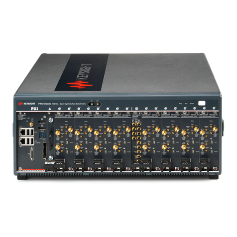
Keysight M9410A/M9411A
VXT PXIe Vector Transceiver
Getting
Started Guide

Notices
© Keysight Technologies, Inc.
2018-2019
No part of this manual may be
reproduced in any form or by any
means (including electronic storage
and retrieval or translation into a
foreign language) without prior
agreement and written consent from
Keysight Technologies, Inc. as
governed by United States and
international copyright laws.
Trademark Acknowledgments
Manual Part Number
M9410-90003
Edition
Edition 1, March 2019
Printed in Malaysia
Published by:
Keysight Technologies
No 116 Tianfu 4th Street
Chengdu, China 610041
Warranty
THE MATERIAL CONTAINED IN THIS
DOCUMENT IS PROVIDED “AS IS,”
AND IS SUBJECT TO BEING
CHANGED, WITHOUT NOTICE, IN
FUTURE EDITIONS. FURTHER, TO
THE MAXIMUM EXTENT PERMITTED
BY APPLICABLE LAW, KEYSIGHT
DISCLAIMS ALL WARRANTIES,
EITHER EXPRESS OR IMPLIED WITH
REGARD TO THIS MANUAL AND
ANY INFORMATION CONTAINED
HEREIN, INCLUDING BUT NOT
LIMITED TO THE IMPLIED
WARRANTIES OF
MERCHANTABILITY AND FITNESS
FOR A PARTICULAR PURPOSE.
KEYSIGHT SHALL NOT BE LIABLE
FOR ERRORS OR FOR INCIDENTAL
OR CONSEQUENTIAL DAMAGES IN
CONNECTION WITH THE
FURNISHING, USE, OR
PERFORMANCE OF THIS
DOCUMENT OR ANY INFORMATION
CONTAINED HEREIN. SHOULD
KEYSIGHT AND THE USER HAVE A
SEPARATE WRITTEN AGREEMENT
WITH WARRANTY TERMS
COVERING THE MATERIAL IN THIS
DOCUMENT THAT CONFLICT WITH
THESE TERMS, THE WARRANTY
TERMS IN THE SEPARATE
AGREEMENT WILL CONTROL.
Technology Licenses
The hardware and/or software
described in this document are
furnished under a license and may be
used or copied only in accordance
with the terms of such license.
U.S. Government Rights
The Software is “commercial
computer software,” as defined
by Federal Acquisition Regulation
(“FAR”) 2.101. Pursuant to FAR
12.212 and 27.405-3 and
Department of Defense FAR
Supplement (“DFARS”) 227.7202,
the U.S. government acquires
commercial computer software
under the same terms by which
the software is customarily
provided to the public.
Accordingly, Keysight provides
the Software to U.S. government
customers under its standard
commercial license, which is
embodied in its End User License
Agreement (EULA), a copy of
which can be found at
http://www.keysight.com/find/sweula
The license set forth in the EULA
represents the exclusive authority
by which the U.S. government
may use, modify, distribute, or
disclose the Software. The EULA
and the license set forth therein,
does not require or permit,
among other things, that
Keysight: (1) Furnish technical
information related to
commercial computer software
or commercial computer
software documentation that is
not customarily provided to the
public; or (2) Relinquish to, or
otherwise provide, the
government rights in excess of
these rights customarily provided
to the public to use, modify,
reproduce, release, perform,
display, or disclose commercial
computer software or
commercial computer software
documentation. No additional
government requirements
beyond those set forth in the
EULA shall apply, except to the
extent that those terms, rights, or
licenses are explicitly required
from all providers of commercial
computer software pursuant to
the FAR and the DFARS and are
set forth specifically in writing
elsewhere in the EULA. Keysight
shall be under no obligation to
update, revise or otherwise
modify the Software. With
respect to any technical data as
defined by FAR 2.101, pursuant
to FAR 12.211 and 27.404.2 and
DFARS 227.7102, the U.S.
government acquires no greater
than Limited Rights as defined in
FAR 27.401 or DFAR 227.7103-5
(c), as applicable in any technical
data.
Safety Notices
A CAUTION notice denotes a hazard. It
calls attention to an operating
procedure, practice, or the like that,
if not correctly performed or adhered
to, could result in damage to the
product or loss of important data. Do
not proceed beyond a CAUTION
notice until the indicated conditions
are fully understood and met.
A WARNING notice denotes a hazard.
It calls attention to an operating
procedure, practice, or the like that,
if not correctly performed or adhered
to, could result in personal injury or
death. Do not proceed beyond a
WARNING notice until the indicated
conditions are fully understood and
met.
3
In This Guide…
The scope of this Getting Started Guide is to detail the processes of receiving and
installing the modules of the Keysight M9410A/M9411A VXT Vector Transceiver.
Additionally, installing the required software is documented. If you have any questions
after reviewing this information, please contact your local Keysight Technologies Inc.
representative or contact us through our website at www.keysight.com/find/m9410a
and www.keysight.com/find/m9411a
1 Unpack and Verify the Shipment Contents
This chapter provides the process to unpack and verify the contents of the signal transceiver.
2 Installing Hard wares
Refer to this chapter to install all the needed hardwares in a PXI Express chassis.
3 Installing the Software and Licensing
This chapter guides you to install the Modular TRX software and redeem application license in
Microsoft Windows 10.
4 Launching Modular TRX Application
This chapter describes the process to launch a modular TRX application in Microsoft Windows 10.
5 Running Modular TRX Application
This chapter provides some guidelines for using the transceiver.
6 Service information
This chapter details some basic service information and how to return a transceiver for service.

4
Where to Find the Latest Information
Documentation is updated periodically. For the latest information about the product, including instrument
software upgrades, application information, and product information, browse to one of the following URLs:
http://www.keysight.com/find/m9410a
http://www.keysight.com/find/m9411a
The documentation associated with this product is available at the M9410A/M9411A product pages on
keysight.com (go to Document Library > Manuals).
To receive the latest updates by email, subscribe to Keysight Email Updates at the following URL:
http://www.keysight.com/find/emailupdates
Information on preventing transceiver damage can be found at:
http://www.keysight.com/find/PreventingInstrumentRepair
Is your product software up-to-date?
Periodically, Keysight releases software updates to fix known defects and incorporate product
enhancements. To search for software updates for your product, go to the Keysight Technical Support
website at:
http://www.keysight.com/find/techsupport

Contents
5
1 Unpack and Verify the Shipment Contents
Initial Inspection..........................................................................................................10
Electrostatic Discharge Protection..........................................................................10
Inspect for Damage..................................................................................................10
Verify M9410A/M9411A Shipment Contents.............................................................11
Instrument Symbols....................................................................................................12
2 Hardware Installation
Chassis and Controller Preparation............................................................................14
Hardware Requirement............................................................................................14
Controller System Requirement...............................................................................15
Power Up the Controller...........................................................................................15
Install Modules............................................................................................................16
M9410A/M9411A Front Panel Overview.....................................................................19
M9300A Reference Preparation..................................................................................21
3 Software Installation and Licensing
Get the M9410A/M9411A software............................................................................26
Software Installation...................................................................................................27
Uninstalling the Software.........................................................................................31
If Installation Fails....................................................................................................31
Keysight M9410A/M9411A Signal Transceiver Licensing Options............................34
Fixed Licenses..........................................................................................................34
Transportable Licenses............................................................................................35
Network Licenses.....................................................................................................35
USB Portable Licenses.............................................................................................36
Configuring Network and USB Licenses..................................................................37
Licensing Measurement Application Software - After Initial Purchase.....................38
Install License by Using a USB Storage Device......................................................38
Install License by Using License Manager...............................................................40
Transporting a License................................................................................................42

6
Contents
4 Launching Modular TRX Application
Configure Application Tool.........................................................................................44
Application Launcher..................................................................................................45
Start Launcher..........................................................................................................45
Launcher Features...................................................................................................47
Hardware License Installation.................................................................................51
Launching Modular TRX Application with Launcher..................................................52
Launch Modular TRX Application Manually............................................................52
Launch Modular TRX Application Automatically.....................................................53
Launch Modular TRX Application by Programming Codes.....................................55
Launch Modular TRX Application by IVI driver........................................................55
5 Using Modular TRX application
Remote Desktop: Using the M9410A/M9411A Remotely..........................................58
Overview of Remote Desktop operation..................................................................58
Setting up Remote Desktop operation....................................................................58
How to locate the computer name/IP address of the Controller.............................59
Running a Remote Desktop session........................................................................60
Display Features..........................................................................................................61
Invalid Data Indicator...............................................................................................61
Screen Tabs..............................................................................................................62
Meas Bar..................................................................................................................63
Measurement Display..............................................................................................64
Menu Panel...............................................................................................................65
Bottom Bar...............................................................................................................66
Function Verification - Making a Basic Measurement................................................67
Protecting Against Overpowering............................................................................68
Using the Interactive Help System............................................................................69

Contents
7
6 Service Information
Calling Keysight Technologies.................................................................................72
Locations for Keysight Technologies.......................................................................72
Read the Warranty...................................................................................................73
Service Options........................................................................................................73

8
Contents

9
Keysight M9410A/M9411A
VXT Vector Transceiver
Getting Started Guide
1 Unpack and Verify the Shipment Contents
This section explains how to verify the shipment contents when you receive the
shipment.
The following topics can be found in this section:
"Initial Inspection" on page 10
"Verify M9410A/M9411A Shipment Contents" on page 11
"Instrument Symbols" on page 12

10
Unpack and Verify the Shipment Contents
Initial Inspection
Initial Inspection
Inspect the shipping container and the cushioning material for signs of stress.
Retain the shipping materials for future use, as you may wish to ship the unit to
another location or to Keysight Technologies for service.
Electrostatic Discharge Protection
Electrostatic discharge (ESD) can damage or destroy electronic components
(the possibility of unseen damage caused by ESD is present whenever
components are transported, stored, or used).
Inspect for Damage
After unpacking a module, inspect it for any shipping damage. Report any
damage to the shipping agent immediately, as such damage is not covered by
the warranty.
If the shipping materials are damaged or the contents of the container are
incomplete:
• Contact the nearest Keysight Technologies office.
• Keep the shipping materials for the carrier’s inspection.
• If you must return a transceiver to Keysight Technologies, use the original
(or comparable) shipping materials.
The modules are shipped in materials which prevent damage from static.
The modules should only be removed from the packaging in an anti-static
area ensuring that correct anti-static precautions are taken. Store all
modules in anti-static envelopes when not in use.
Do NOT use these techniques for a static-safe work station when working
on circuitry with a voltage potential greater than 500 volts.
To avoid damage when handling a module, do not touch exposed
connector pins.
Transceiver damage can result from using packaging materials other than
those specified. Never use styrene pellets in any shape as packaging
materials. They do not adequately cushion the equipment or prevent it
from shifting in the carton. They cause equipment damage by generating
static electricity and by lodging in the transceiver, blocking airflow.

11
Unpack and Verify the Shipment Contents
Verify M9410A/M9411A Shipment Contents
Please verify the standard shipment contents according to the table below.
The optional cables are listed as below:
Qty Part Number Description
1 9230-0333 Envelope-calibration certificate
1 5061-7383 South Korean Class A EMC Declaration
1 9320-6698 China RoHS Addendum
1 9320-6797 Keysight Safety Leaflet
1 M9410-90001 M9410A/M9411A Product DVD
1 M9410-90002 Installation Note
1 M9410-90003 M9410A/M9411A Getting Started Guide
1 M9410-60009 Cable Assembly-MMPX to SMB
1 M9410A/M9411A M9410A/M9411A VXT Vector Transceiver
Qty Part Number Description
1 Y1810A Cable, MMPX male to SMB male, 260 mm
1 Y1811A Cable, MMPX male to MMPX male, 200 mm
1 Y1812A Cable, MMPX male to SMB male, 500 mm
1 Y1813A Cable, MMPX male to SMB male, 1000 mm
1 Y1814A Cable, SMA male to SMA male, 1220 mm
1 Y1815A Cable, MMPX male to BNC male, 1500 mm
All the manuals and software contained on the DVD are available from
www.keysight.com/find/m9410a
www.keysight.com/find/m9411a

12
Unpack and Verify the Shipment Contents
Instrument Symbols
Instrument Symbols
The instruction documentation symbol. The product is
marked with this symbol when it is necessary for the user to
refer to instructions in the documentation.
The CE mark is a registered trademark of the European
Community.
All Level 1, 2 or 3 electrical equipment offered for sale in
Australia and New Zealand by Responsible Suppliers must be
marked with the Regulatory Compliance Mark.
This is a marking of a product in compliance with the
Canadian Interference-Causing Equipment Standard
(ICES-001). This is also a symbol of an Industrial Scientific
and Medical Group 1 Class A product (CISPR 11, Clause 4).
This symbol indicates separate collection for electrical and
electronic equipment mandated under EU law as of August
13, 2005. All electric and electronic equipment are required to
be separated from normal waste for disposal (Reference
WEEE Directive 2002/96/EC).
Indicates the time period during which no hazardous or toxic
substance elements are expected to leak or deteriorate
during normal use. Forty years is the expected useful life of
the product.
This hot surface symbol is to remind users not to touch hot
surfaces of the module when the chassis is just powered off.
This equipment is Class A suitable for professional use and is
for use in electromagnetic environments outside of the home.

13
Keysight M9410A/M9411A
VXT Vector Transceiver
Getting Started Guide
2 Hardware Installation
This chapter describes the preparation of hardware for M9410A/M9411A VXT
Vector Transceiver.
"Chassis and Controller Preparation" on page 14
"Install Modules" on page 16
"M9410A/M9411A Front Panel Overview" on page 19
"M9300A Reference Preparation" on page 21

14
Hardware Installation
Chassis and Controller Preparation
Before installing the M9410A/M9411A software, some preparation work is
needed. Please refer to the sections below to be familiar with those
requirements.
Hardware Requirement
To successfully install and run M9410A/M9411A software, the chassis and
controller/PC with the configuration as below is required:
Please refer to M9410A/M9411A Configuration Guide for further description of
hardware configuration.
Topic Requirements
Chassis PXIe or PXI-H chassis slot (Keysight M9018B/M9019A PXIe
chassis is recommended)
Controller Embedded controller
Keysight M9037A or an equivalent embedded controller that
meets the following requirements:
• A PXIe system controller (PXI-1 embedded controllers are
not compatible).
• Utilizes a 2x8, 4x4, or 1x8 PXIe system slot link
configuration.
• Runs one of the operating systems listed in Controller
System Requirement.
Or remote controller
A PC running one of the operating systems listed in Controller
System Requirement and a Keysight M9021A/22A/23A Cable
Interface with the following PC interface configuration:
• Keysight M9048B PCIe Desktop Adapter x8, with Y1202A
PCIe cable (for a desktop PC).

15
Hardware Installation
Chassis and Controller Preparation
Controller System Requirement
To successfully install and run M9410A/M9411A software, the controller/PC
with the configuration as below is required:
Power Up the Controller
If you are using a remote controller, perform the following steps:
1. Install a PCIe cable interface between the remote controller and the
chassis.
2. Power up the chassis after all the modulars are installed properly.
3. Power up the PC.
If you are using an embedded controller, perform the following steps:
1. Refer to "Install Modules" on page 16 to Install the embedded controller
module into a compatible chassis.
2. Connect peripherals (mouse, keyboard, monitor).
3. Power up the chassis after all the modulars are installed properly.
Topic One Module
Operating system Window 7/10 (64-bit), English Version
Processor Single Core with hyper threading, 1.86 GHz minimum
Available memory for each
module
8 GB minimum,
16 GB or greater recommended
Available disk space for
each modular on Drive C:
8 GB or greater recommended
If you are using a remote controller and you have installed the interface
cable, you must power up the chassis BEFORE you power up the PC.
When you power down your system, shut down the PC BEFORE you power
down the chassis.

16
Hardware Installation
Install Modules
Install Modules
Before installing a M9410A/M9411A module and an embedded controller
module into a PXI express chassis, please read all the safety information
carefully and make sure the chassis is in a proper condition as below.
• Ensure proper chassis air flow is maintained. The chassis has multiple air
intakes located on the lower sides, lower front and bottom front of chassis.
• Select a chassis that provides thermal protection if fans become inoperable
or forced air cooling is obstructed
• Use slot blockers and EMC filler panels in empty module slots to ensure
proper operating temperatures. Keysight chassis and slot blockers optimize
module temperature performance and reliability of test.
• Set chassis fans to high or auto. Do not disable fans.
• Position chassis to allow plenty of space around chassis air intake and fan
exhaust.
• At environment temperatures above 45°C, set chassis fan speed to high.
Keysight Technologies does not warrant third-party system-level
(combination of chassis, controllers, modules, etc.) performance, safety, or
regulatory compliance, unless specifically stated.
PXI hardware does not support "hot-swap" (changing modules while
power is applied to the chassis) capabilities. Before installing or removing
a module to/from the chassis, power off the chassis to prevent damage to
the module.
Lack of airflow may cause module creates a hazard, it relies on the chassis
for protection.
The module can be installed in any PXIe or hybrid PXIe slot
marked with a peripheral slot compatibility image (solid black
circle for PXIe, or solid black circle with the letter -H- for hybrid).

17
Hardware Installation
Install Modules
Please refer to the chassis documentation for further information about how to
use the chassis.
Perform the following steps to install a module in a chassis:
1. Make sure the line cord is plugged in to establish earth ground and the
chassis power switch is in the Off (Standby) position.
2. Wear a grounded wrist strap for this procedure.
3. If the chassis has multiple fan speed settings, ensure the fans are set to
automatic. Do not set the fan speed to low or turn it off.
4. Position the chassis so that there is ample space between the chassis fan
intake and exhaust vents. Blockage by walls or obstructions affects the air
flow needed for cooling.
5. Before inserting the module into the chassis, back the mounting screws out
to assure that there is no interference between the screws and the
mounting rails. Inspect the chassis slot to ensure there are no bent pins on
the slot connectors.
6. Holding the module by the injector/ejector handle, slide it into a slot, as
shown in callouts 4 – 6 in the following figure.
a.Install the module into the slot of the chassis by placing the module card
edges into the front module guides (top and bottom).
b.Slide the module to the rear of the chassis and ensure that the
injector/ejector handle is pushed down in the unlatched (downward)
position.

18
Hardware Installation
Install Modules
c.Slide the module completely into the chassis. When you begin to feel
resistance, pull up on the injector/ejector handle to fully inject the
module into the chassis.
7. Repeat for other modules, if present.
8. Tighten the top mounting screw (see callout 7 in Figure above) and the
bottom mounting screw (located below the injector/ejector handle) on the
module(s) using a Phillips #1 torque drive set to 4 in-lbs (0.45 N.m).
Performance may suffer if the screws are not tightened properly.
9. Verify the PXI chassis fans are operable and free of dust and other
contaminants that may restrict airflow.
10.Install filler panels and slot blockers after installing the modules. Missing
filler panels or slot blockers may disrupt air circulation in the chassis. The
leftmost slot does not accept a slot blocker.
11.If you are using a PCIe Cable Interface, such as the Keysight
M9021A/22A/23A, connect the Cable Interface in the chassis to the PC
host per the instructions that came with the Cable Interface.
12.Plug in and power on the chassis.
13.If you are using a remote controller, reboot the remote controller.

19
Hardware Installation
M9410A/M9411A Front Panel Overview
M9410A M9411A
Item Description Remark
#PortName
1100 MHz Out 100 MHz reference output MMPX female connector, 50 Ωnominal
2RFOutput RF output port SMA female connector, 50 Ωnominal
Maximum reverse input power: +30 dBm
3100 MHz In 100 MHz reference input MMPX female connector, 50 Ωnominal
44.8 GHz Out 4.8 GHz timebase output MMPX female connector, 50 Ωnominal
5Half Duplex Half duplex port for RF
Input or RF Output
(Option HDX)
Maximum safe input power: +27 dBm
64.8 GHz In 4.8 GHz timebase input MMPX female connector, 50 Ωnominal

20
Hardware Installation
M9410A/M9411A Front Panel Overview
7 Status LED LED indicator of the
module status
Green: Modular TRX application is running normally.
Red: Modular TRX application has been invoked with
error, error message has been logging into event
viewer.
Blink: if blink red, it means FPGA is updating on the
module. If blink green, it means operation of flash
access. The frequency of blink is about 1 Hz.
Off: The module is not in above situations.
8Trig1 Receiver or Source Trigger
port
MMPX female connector
Input or Output, selectable
Input impedance: 1 kΩor 50 Ωnominal
Input level range: -3.3 V to +3.3 V
Output impedance: 50 Ωnominal
Output level range: 3.3 V LVTTL
9RF Input RF Input port Maximum average input power: +27 dBm
10 Trig 2 Receiver or Source Trigger
port
MMPX female connector
Input or Output, selectable
Input impedance: 1 kΩor 50 Ωnominal
Input level range: -3.3 V to +3.3 V
Output impedance: 50 Ωnominal
Output level range: 3.3 V LVTTL
11 Ctrl S Slave uHDMI Slave uHDMI female connector
12 Ctrl M Master uHDMI Master uHDMI female connector
13 Status (ODI) LED for indicating the
ODI status
14 RX FC RX Flow Control Rx Flow Control over SMB connector
15 TX FC TX Flow Control Tx Flow Control over SMB connector
16 ODI ODI connector
(Option ODI)
24-fiber optical cable with ODI connector
Item Description Remark
#PortName
This manual suits for next models
1
Table of contents
Other Keysight Transceiver manuals

Keysight
Keysight S9115A User manual

Keysight
Keysight M9471A User manual

Keysight
Keysight M9420A User manual

Keysight
Keysight S9100A User manual

Keysight
Keysight E7760B User manual

Keysight
Keysight M1742A User manual

Keysight
Keysight S9100A User guide

Keysight
Keysight S9100A User guide

Keysight
Keysight N7081A User manual
Popular Transceiver manuals by other brands

Transition Networks
Transition Networks E-TBT-MCO1 installation instructions

Kenwood
Kenwood TH-28A instruction manual

Barrett
Barrett 550 user manual

Ritron
Ritron DTX- 60 Series operating manual

Williams Sound
Williams Sound Digi-Wave 300 Series user manual

Comnet
Comnet FVT1014 Installation and operation manual